Table of Contents
Advertisement
Quick Links
NOTE:
This Stator replaces the following 2, 3, and 4 cylinder P/N's: 398-818535A17 and A18, 398-9710A11, A12, A14, A15, A17, A18, A22, A23,
A25, A28, A30, A31, A33, A34, A35 A36, A38, A39, A43, A45, A46, A47, A48, and A49. 398-9873A 4, A 9, A17, A19, A24, A25, A29, A32,
A33, A35, and A38. 398-81853517, and F747095.
Warning! This product is designed for installation by a professional marine mechanic. CDI Electronics cannot be held liable for
injury or damage resulting from improper installation, abuse, neglect, or misuse of this product.
Note: 174-9710K1 requires a Voltage Regulator, DO NOT USE WITH A RECTIFIER ONLY.
It is recommended that dielectric grease (i.e. CDI 991-9705) be used in the bullet nose connectors to help prevent corrosion.
Any sign of leakage out of the Ignition charge coils or bubbling around the battery charge windings indicate a bad Stator. Check for burned
marks on each pole. If a problem is found on the battery windings, we recommend the Voltage Regulator be closely checked. To replace
Stators with ring terminals, please use the bullet to ring adapters enclosed with this Stator.
If this Stator is to be used as a replacement for the Mercury "Red" Stator, connect all wires to the Switchbox in their designated
position. The Adapter Module used with the Red Stator is no longer needed.
If this Stator is to be used on a three cylinder engine, connect the Red/White and Blue/White striped wires to engine ground.
1.
Disconnect the Stator wires from the Switchbox, engine ground, and the Voltage Regulator.
2.
Remove the flywheel according to the service manual for your engine.
3.
Mark the position of the mounting screws in relation to where the Stator wires come out of the old Stator and remove the old Stator.
4.
Orient and install the new Stator (using a good thread-locker applied to the bolts) in the same position as the old Stator on the engine
and install the flywheel by following the service manual instructions.
5.
Connect the Yellow wires from the Stator to the Voltage Regulator, ignoring any stripes on the Voltage Regulator's Yellow wires.
6.
Connect the Stator leads as follows:
New Stator
Red (High speed Coil)
Blue (Low speed Coil)
Red/White (High speed Coil)
Blue/White (Low speed Coil)
7.
If this Stator is to be used on a 3 cylinder engine application, connect the Red/White and Blue/White striped wires to a known good
engine ground.
8.
If your engine used a Mercury Red Stator Kit, it is normal for that application to have NOT used the Red and the Red/White wire (or
Red and Red/White stud post on a studded Switchbox). These are usually either taped up or capped off. With the CDI Electronics 194-
9710K 1 Stator, the Red and Red/White wire WILL be used. Find the Red wire (or Red stud post on a studded Switchbox) and connect
the Solid Red wire from the New Stator to the Switchbox. On a 2 and 4 cylinder application, connect the Red/White wire to the
switchbox in its appropriate place. On a 3 cylinder application, connect the remaining Red/White and Blue/White striped wires to a
known good engine ground.
9.
Replace the flywheel according to the service manual.
HOW TO TEST THE ENGINE STOP CIRCUIT (KILL) FOR DC VOLTAGE:
1.
DC voltage present on the kill circuit of the Switchbox due to a faulty key switch, boat harness, or engine harness will severely damage
the Switchbox's internal kill circuit. Connect a Digital Multi Meter to the Ignition Stop wire(s) AT THE SWITCHBOX while disconnected
from the Switchbox in reference to a known good engine ground. Turn the Ignition switch on and off several times. If, at any time, you
see over 2 VDC on the kill wire(s), there is a problem with one or both harnesses and/or the Ignition switch. The Ignition Stop wire
should not be connected back to the new Switchbox at any point until the problem is corrected OR DAMAGE TO THE SWITCHBOX
WILL OCCUR!
NO FIRE ON ANY CYLINDER:
1.
Perform a visual inspection of the Stator and Trigger wiring to the Switchbox. Check to make sure that the wiring is correct, clean and
free of corrosion, and that all connections are tight.
Web Support:
All rights reserved. Reproduction or use of content, in any manner, without express written permission by CDI Electronics, LLC., is prohibited.
Rev J • 4/7/2021
Installation and Troubleshooting Guide
This installation is to be completed by an Authorized Dealer or Professional Service
Technician. For questions regarding installation or warranty, call CDI Tech Support
at 866-423-4832. Do not return to the Dealer or Distributor where the part was purchased.
Contact CDI Electronics Directly for Return Material Authorization.
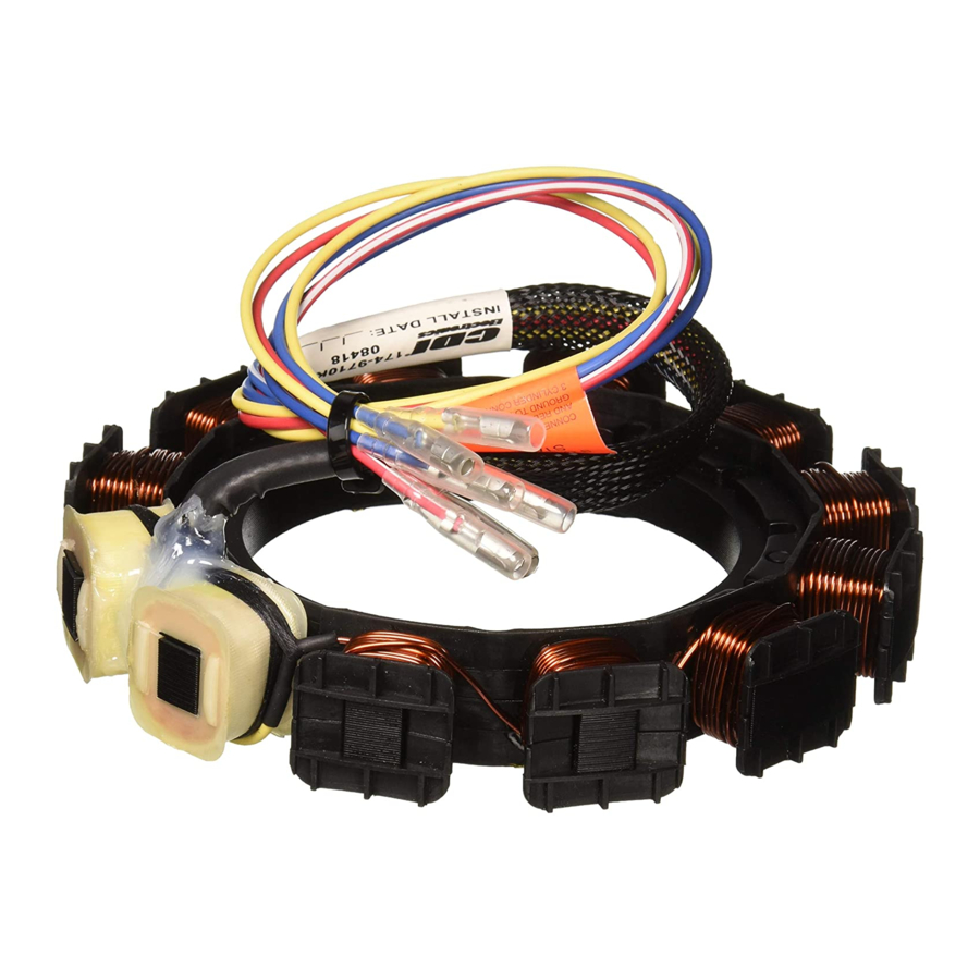
CDI P/N: 174-9710K 1
2 Cylinder Switchbox
Red (High speed Coil)
Blue (Low speed Coil)
Red/White (High speed Coil)
Blue/White (Low speed Coil)
TROUBLESHOOTING
CDI Electronics, LLC • 353 James Record Road SW • Huntsville, AL 35824 USA
www.cdielectronics.com
INSTALLATION
3 Cylinder Switchbox
Red (High speed Coil)
Blue (Low speed Coil)
Engine Ground
Engine Ground
• Tech Support: 1-866-423-4832 • Order Parts: 1-800-467-3371
Page - 1 of 3
4 Cylinder Switchbox
Red (High speed Coil)
Blue (Low speed Coil)
Red/White Stripe (High speed Coil)
Blue/White Stripe (Low speed Coil)
QF-358
Advertisement
Table of Contents

Related Manuals for CDI 174-9710K 1


Summary of Contents for CDI 174-9710K 1
- Page 1 If your engine used a Mercury Red Stator Kit, it is normal for that application to have NOT used the Red and the Red/White wire (or Red and Red/White stud post on a studded Switchbox). These are usually either taped up or capped off. With the CDI Electronics 194- 9710K 1 Stator, the Red and Red/White wire WILL be used.
- Page 2 Web Support: www.cdielectronics.com • Tech Support: 1-866-423-4832 • Order Parts: 1-800-467-3371 All rights reserved. Reproduction or use of content, in any manner, without express written permission by CDI Electronics, LLC., is prohibited. Rev J • 4/7/2021 Page - 2 of 3...
- Page 3 Web Support: www.cdielectronics.com • Tech Support: 1-866-423-4832 • Order Parts: 1-800-467-3371 All rights reserved. Reproduction or use of content, in any manner, without express written permission by CDI Electronics, LLC., is prohibited. Rev J • 4/7/2021 Page - 3 of 3...
Need help?
Do you have a question about the 174-9710K 1 and is the answer not in the manual?
Questions and answers