Table of Contents
Advertisement
Quick Links
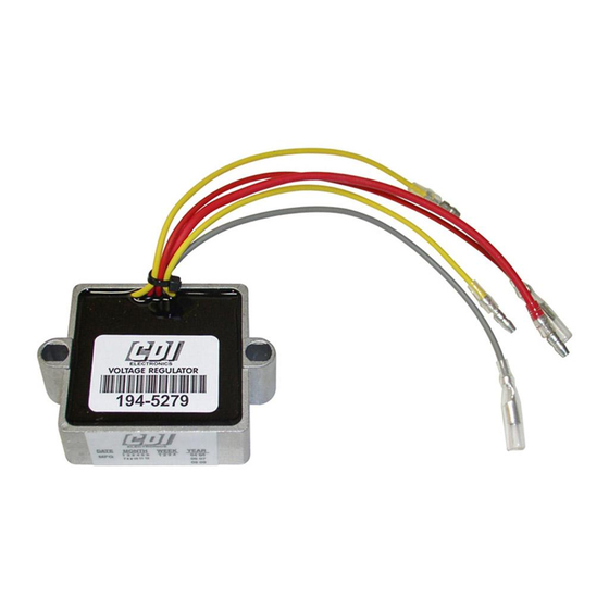
CDI P/N: 194-5279 Regulator/Rectifier 2, 3, 4, & 6 Cylinder
This kit will replace all of the 815279, 817411, 830179, 854515, 856747, 856748 and 883072 series regulator/rectifiers,
the 194-3072K1 and the (12082A1 regulator, 62351A1 rectifier, and 17602A1 tachometer terminal combination.)
WARNINGS:
This product is designed for installation by a professional marine mechanic. CDI cannot be held liable for
injury or damage resulting from improper installation, abuse, neglect or misuse of this product.
DO NOT USE A MAINTAINENCE FREE, AGM OR DRY CELL BATTERIES AS THE USE OF THESE TYPE BATTERIES
COULD VOID THE WARRANTY AND DAMAGE THE
NEVER DISCONNECT THE BATTERY WHILE THE ENGINE IS RUNNING AS THIS MAY DAMAGE THE
REGULATOR/RECTIFIER. If the boat is equipped with a battery switch, make sure that it is a make before break type.
SERVICE NOTE: DO NOT REMOVE THE Y JUMPER FROM THE RED WIRES UNLESS THE OLD
REGULATOR/RECTIFIER HAD 2 RED WIRES CONNECTED TO IT AS BOTH RED WIRES MUST BE
CONNECTED TO 12 VDC IN ORDER FOR THE REGULATOR/RECTIFIER TO WORK.
1. Disconnect the battery negative post.
2. Disconnect and remove the old regulator/rectifier.
3. If the unit being replaced has long Red and Yellow wires; Cut the wires off close to the case of the old
regulator/rectifier, and crimp and solder the new terminals on to the wires. Use the wires on the new rectifier/regulator
as a guide for terminal selection. Remember, Both Red wires must be connected to battery Positive 12 VDC for the
Regulator/Rectifier to work.
4. Use a quality heat-sink compound (CDI P/N: 989-8109) on the back of the regulator when you install the new
regulator/rectifier.
5.
Connect all wires to the new Regulator/Rectifier, matching wire colors. Do not remove the jumper on the Red wires unless the
old Regulator/Rectifier had Two Red wires connected to it as both Red wires on the new Regulator/Rectifier must be
connected to 12 VDC for the new Regulator/Rectifier to work. A Grey or Black stripe on the stator's Yellow wires can be
connected to either Yellow wire of the Regulator/Rectifier.
6. The normal wire connections is shown below:
RECTIFIER/REGULATOR
Yellow (2)
Grey
Red (With Y jumper installed)
Case
RECTIFIER/REGULATOR # 1 CONNECT TO
Yellow (2)
Grey
Red (Small)
Red (Large)
Case
RECTIFIER/REGULATOR # 2 CONNECT TO
Yellow (2)
Grey
Red (Small)
Red (Large)
Case
SERVICE NOTE: It is recommended that dielectric grease (i.e. CDI P/N 991-9705) be used in the bullet nose connectors
to help prevent corrosion.
INSTALLATION NOTE: These regulator/rectifiers may cause a small spark when you reconnect the battery and will draw
a very small amount of current from the battery (Less than 0.001 amp).
Web Support:
All rights reserved. Reproduction or use of content, in any manner, without express written permission by CDI Electronics, LLC., is prohibited.
Rev J 8/9/2019
Installation and Troubleshooting Guide
NOTE: This installation is to be completed by an Authorized Dealer or Professional Service
Technician. For questions regarding installation or warranty, call CDI Tech Support
at 866-423-4832. Do not return to the Dealer or Distributor where the part was purchased.
Contact CDI Electronics Directly for Return Material Authorization.
9 AND 16 AMP STATOR WITH 2 YELLOW WIRES
CONNECT TO
Stator Yellow (Stripes on these wires can be ignored)
Tachometer
Red wire from the harness to the Positive post of starter solenoid.
Connects through the mounting bolts to engine ground.
40 AMP STATOR WITH 4 YELLOW WIRES
Stator Short Yellow wires (Stripes on these wires can be ignored)
Tachometer
Red wire from the harness to the Positive post of starter solenoid.
Red wire from the harness to the Positive post of starter solenoid.
Connects through the mounting bolts to engine ground.
Stator Long Yellow wires (Stripes on these wires can be ignored)
No Connection
Red wire from the harness to the Positive post of starter solenoid.
Red wire from the harness to the Positive post of starter solenoid.
Connects through the mounting bolts to engine ground.
CDI Electronics, LLC 353 James Record Road SW Huntsville, AL 35824 USA
www.cdielectronics.com
REGULATOR/RECTIFIER AND OR THE STATOR
Tech Support: 1-866-423-4832 Order Parts: 1-800-467-3371
Page - 1 of 2
!!!
QF-358
Advertisement
Table of Contents

Related Manuals for CDI 194-5279


Summary of Contents for CDI 194-5279
- Page 1 Web Support: www.cdielectronics.com Tech Support: 1-866-423-4832 Order Parts: 1-800-467-3371 All rights reserved. Reproduction or use of content, in any manner, without express written permission by CDI Electronics, LLC., is prohibited. Rev J 8/9/2019 Page - 1 of 2...
- Page 2 Web Support: www.cdielectronics.com Tech Support: 1-866-423-4832 Order Parts: 1-800-467-3371 All rights reserved. Reproduction or use of content, in any manner, without express written permission by CDI Electronics, LLC., is prohibited. Rev J 8/9/2019 Page - 2 of 2...
Need help?
Do you have a question about the 194-5279 and is the answer not in the manual?
Questions and answers