Advertisement
Key Features
•
D ownward Firing Speaker Will Not Collect Dust or Condensation
•
R ugged Construction Can Support Up To 250 lbs
•
E asy Bayonet Attachment of Head Unit To Base, Enables Installation
of Base During Excavation and Installation of Head Unit After
Landscaping Has Been Completed
•
A vailable in 70.7V or 8Ω Versions
•
E asy Conduit Installation in Large and Small Base With Dedicated
Mounting Pads
•
S peaker Protected By Triple Layer Grille
•
S mall Base (ATS100GS) has Drill Points for 4" Square, 2-Gang EO
Box, or 1-Gang Box Mounting to a Deck or Slab
1601 JACK MCKAY BLVD.
ENNIS, TEXAS 75119 U.S.A.
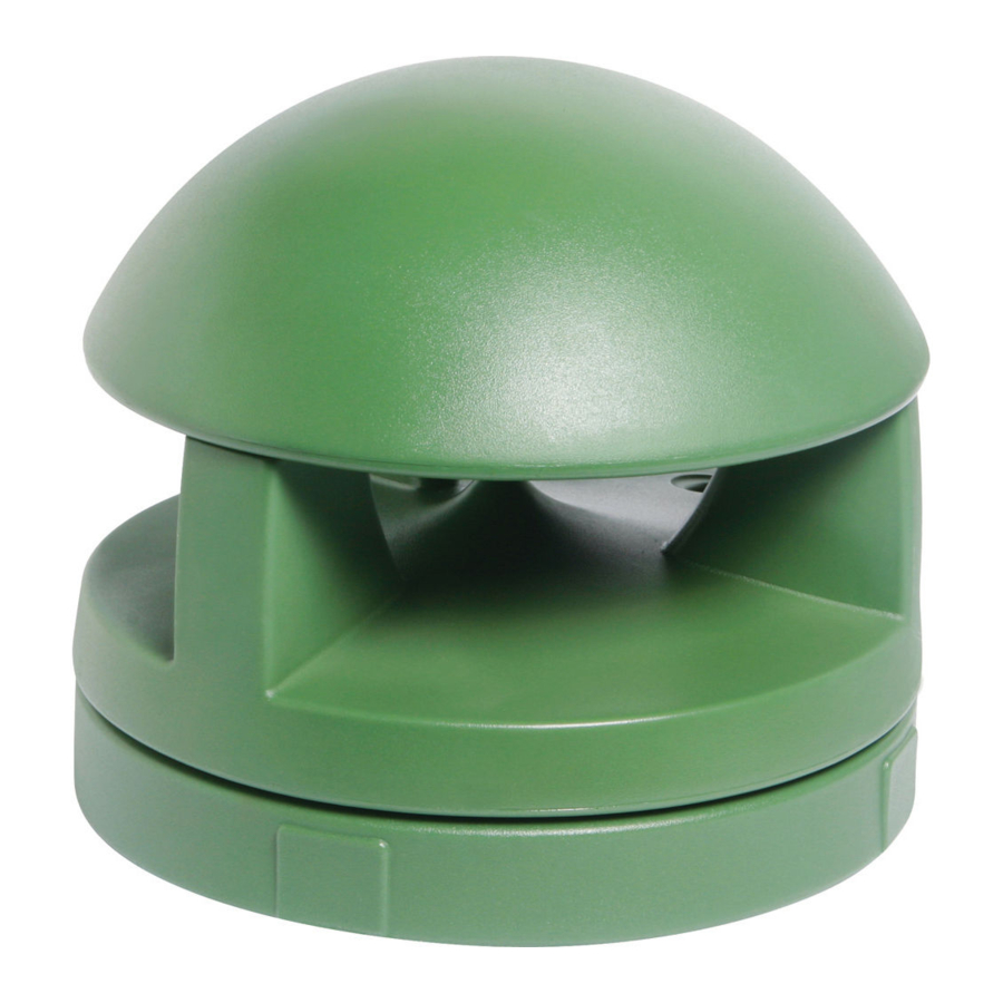
ATS100 Series
Garden Speakers
ATS100 Series Instructions
To Install Large Base:
1. M ake sure you have a path to bury wire connected to speaker.
2. D ig a hole 8" deep x 30" diameter.
3. R un wire to hole.
4. A ttach conduit or gland nut to flats on base.
5. B ring in wire and leave sufficient cable for adequate service loop
6. F ill base with clean dirt or sand to within 2"-3" of top for optimum
7. C over with provided temporary lid and attach with provided
8. B ack fill dirt to base. Top of base should be 2" – 3" above ground.
To Install Small Base:
If Using an EO Box:
1. I nstall 1-Gang, 2-Gang, or 4" x 4" box flush to mounting surface.
2. C ut out scribed line on bottom of base for 1- or 2-gang box.
Head Unit
3. D rill appropriate holes in base (outer 4 holes for 4" x 4", inner 4 for
4. I nstall wiring in box.
5. S et base on box and attach with screws.
If Using Conduit:
1. M ount base to surface with appropriate screws through the base
2. A ttach conduit and bring in wire. Provide for surface loop (minimum
3. C over with provided temporary lid and attach with provided 1"
Large Base
Small Base
TELEPHONE: (800) 876-3333
FAX (800) 765-3435
(minimum 18") to reach head unit.
bass performance.
1" screws if head unit is not to be attached immediately.
2-gang, or 1 set of 2 inner for 1-gang).
bottom.
18").
screws if head unit is not to be attached immediately.
1/2
AtlasSound.com
Advertisement
Table of Contents

Related Manuals for Atlas ATS100 Series


Summary of Contents for Atlas ATS100 Series
- Page 1 ATS100 Series Garden Speakers Key Features ATS100 Series Instructions To Install Large Base: • D ownward Firing Speaker Will Not Collect Dust or Condensation • R ugged Construction Can Support Up To 250 lbs 1. M ake sure you have a path to bury wire connected to speaker. • E asy Bayonet Attachment of Head Unit To Base, Enables Installation 2. D ig a hole 8" deep x 30" diameter. of Base During Excavation and Installation of Head Unit After 3. R un wire to hole. Landscaping Has Been Completed 4. A ttach conduit or gland nut to flats on base.
- Page 2 4. P ush the head unit down into the holes and turn clockwise to lock the head unit in place. 5. P ut a 1" Phillips-head screw (supplied with the base) through the lock- ing screw access hole to secure and prevent removal by unauthor- ized persons. Head Unit 6. P ut stick-on logo cover over access hole. (See Figure 1) 7. S elect transformer tap wattage (70.7V Version Only) using a dime or small screwdriver to adjust stepped switch. (Switch is located on the underside of the “domed” section of the head unit near outer edge.) Insert red weather protection “plug” into recessed switch cavity using thumb to press the cap into place. (See Figure 2) ATS100 SERIES Specifications Frequency Response 43Hz – 20kHz (±7dB) Sensitivity (1W / 1M) 89.5dB (Half Space Reference) Power Handling 70 Watts RMS Horizontal Dispersion 360° Speaker C oaxial 8", Polypropylene / Kevlar Cone with Rubber Surround, ⁄...
Need help?
Do you have a question about the ATS100 Series and is the answer not in the manual?
Questions and answers