Table of Contents
Advertisement
Quick Links
Advertisement
Table of Contents

Related Manuals for Flintec CCWR


Summary of Contents for Flintec CCWR
- Page 1 User Manual CCWR Doc No.0096489 Page 1 of 29 V1.2 Issued 17 Aug 2020...
-
Page 2: Table Of Contents
12. RF Exposure Notice ......................28 12.1. FCC & ISED Canada RF Exposure Notice ..............28 12.2. Avis d'exposition FCC et ISDE Canada RF ..............28 13. CCWR Control Drawing 0090977 ..................29 Doc No.0096489 Page 2 of 29 V1.2 Issued 17 Aug 2020... -
Page 3: Product Description
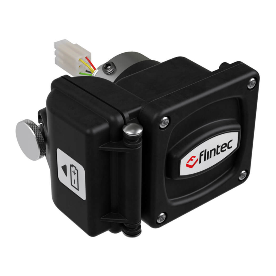
1. Product Description The CCWR is a wireless variant of our CC1 pump-off control load cell. The CCWR in conjunction with an appropriate load cell can transmits polished rod load wirelessly, which solves the industry wide problem of cable failures. After months of development in the field, working hand-in-hand with end users, our design addresses the most demanding concerns raised. -
Page 4: Mounting Instructions
2. Mounting Instructions IMPORTANT The employees responsible for the equipment, installation and verification must take into consideration all the actions concerning this subject specified in IEC 60079-14:2013 ed. 5.0 (Electrical installations design, selection and erection) standard. In addition to general specifications associated with any system installed in hazardous locations, special attention should be paid for specific requirements regarding intrinsic safety. - Page 5 If the magnetic base is not directly attached, due to a non-metallic surface (or space constraints), the base can be suitably fastened to any structure using brackets, plates or other type of support. DIN rail mount Pole mount with U-Bracket _________________________________________________________________ IMPORTANT In order to achieve the best performance the antenna attached to the top...
-
Page 6: Antenna Recommendations
Antenna Recommendations 2.2. Omni Directional Antenna Antenna Height CCWR base unit is equipped with an The base unit antenna can be omni-directional antenna to provide positioned flexibly using the the widest possible signal coverage. antenna extension cable. Mounting the antenna at a higher position to the base ... - Page 7 CCWR - User Manual Enclosure Mounting Doc No.0096489 Page 7 of 29 V1.2 Issued 17 Aug 2020...
-
Page 8: Base Unit Connections
CCWR - User Manual Base Unit Connections 2.3. SIGNAL CABLE COLOR CODE Excitation + / Vref + GREEN mV/V Signal + / mA + WHITE mV/V Signal - / mA - BLACK Excitation - / Vref - YELLOW Shield (NC) -
Page 9: Remote Unit (Wireless Load Cell)
CCWR - User Manual Remote Unit (Wireless Load Cell) 2.4. CCWR is mounted in the same way as other polished rod load cells. No special mounting procedure is required. ________________________________________________________________ IMPORTANT Position the remote unit (with the Flintec logo upright on the plastic enclosure). -
Page 10: Connect Load Cell To Remote Unit
CCWR - User Manual 2.4.1. Connect Load Cell to Remote Unit 1. Loosen the 3 retaining screws. 2. Insert the load cell adaptor (3/4-14 NPT) and keep free/loose from the assembly. Doc No.0096489 Page 10 of 29 V1.2 Issued 17 Aug 2020... - Page 11 CCWR - User Manual Mate the CCWR cable connector to the connector inside the load cell. 4. Fit the load cell adaptor to the load cell over the cable and tighten with a hand tool. Doc No.0096489 Page 11 of 29...
- Page 12 CCWR - User Manual 5. Push the remote assembly into the load cell adaptor, making sure the remote module is level with the load cell and battery compartment. To prevent damage from moving parts like rod rotator arm ensure the assembly is as shown below.
-
Page 13: Battery Installation
CCWR - User Manual 3. Battery Installation CCWR remote unit is powered by a primary cell battery and must be fitted suitably in the battery compartment. The person in charge of the installation must verify the battery undamaged or wet. -
Page 14: Equipment Maintenance
This manual must be read and carefully kept. The manual should be referenced before conducting any fitment or maintenance tasks. Battery Replacement CCWR remote unit (transmitter) is powered from a specific battery. • TADIRAN – TL-5930/F WARNING – Do not replace battery when an explosive atmosphere is present Procedure 1. -
Page 15: Operation
CCWR - User Manual 5. Operation 1. Disconnect or remove the power to the base unit. 2. Ensure the base antenna is connected with an RF filter. The RF filter must always be mounted on the base 3. The remote antenna is installed by the manufacturer; to preserve safety certifications, it is not intended to be removed. -
Page 16: Base Unit Channel Selection
CCWR - User Manual Base Unit Channel Selection 5.1. • To remove the base units top cover, use a crosshead screwdriver to remove the four screws. • Use a small flat-head screwdriver to rotate the rotary channel selection switch to the appropriate channel required. - Page 17 CCWR - User Manual Channel Selector Switch Doc No.0096489 Page 17 of 29 V1.2 Issued 17 Aug 2020...
-
Page 18: Technical Specification
CCWR - User Manual 6. Technical Specification CCWR Retrofit Wireless System Technical Specification Typical System Specifications with Flintec CC1 & Variants/Capacities 30k & 50k Rated Load Output (RO) mV/V 2.00 ± 0.5% Rated Position Output % FS (Stroke) ± 2... - Page 19 CCWR - User Manual Electronics Specification Remote and Base Transceiver Units Matched Mac ID (32bit) Specific; No External Connection - Paired Unit Data Rate Readings/Sec Radio Frequency Band 2.45 Radio Channels Selectable (*) Telemetry Range Feet (Meters) (*) 100 - 1000 (30-300)
-
Page 20: Markings
CCWR - User Manual 7. Markings Remote Unit (Transmitter) 7.1. Label Equipment Group All areas except Mines. Equipment Category & Enviro Gas, Vapor, Mist. Explosion Protection Conformity with some IECs protection modes. Protection Type Intrinsic security “ia” protection mode than mines. Gases Groups. -
Page 21: Product Dimensions
CCWR - User Manual 8. Product Dimensions Generic Load Cell 8.1. All dimensions are in millimeters [in inches] and are subject to change. Doc No.0096489 Page 21 of 29 V1.2 Issued 17 Aug 2020... -
Page 22: Remote Unit
CCWR - User Manual Remote Unit 8.2. All dimensions are in millimeters [in inches] and are subject to change. Doc No.0096489 Page 22 of 29 V1.2 Issued 17 Aug 2020... -
Page 23: Base Unit
CCWR - User Manual Base Unit 8.3. All dimensions are in millimeters [in inches] and are subject to change. Doc No.0096489 Page 23 of 29 V1.2 Issued 17 Aug 2020... -
Page 24: Safety Information
The CCWR may be connected to passive Ex ‘nA’ load cells for use in Zone 2/Division 2 locations provided the rated voltage of the load cell is 3.9V or greater, and provided the wiring is suitable for the location. -
Page 25: X-Mark Conditions
CCWR - User Manual X-Mark Conditions 9.4. The capacitance of exposed isolated metal parts was found to be 53.9 pF. Static Discharge – It is recommended, fitment and maintenance be carried out in electrostatic clothing, whilst wearing gloves and using insulating objects/tools. -
Page 26: Fcc Certification Statement
CCWR - User Manual 10. FCC Certification Statement Note: This equipment has been tested and found to comply with the limits for a Class A digital device, pursuant to part 15 of the FCC Rules. These limits are designed to provide reasonable protection against harmful interference when the equipment is operated in a commercial environment. -
Page 27: Ised Rss-Gen Notice
CCWR - User Manual 11. ISED RSS-Gen Notice “This device complies with Industry Canada’s licence-exempt RSSs. Operation is subject to the following two conditions: 1. This device may not cause interference; and 2. This device must accept any interference, including interference that may cause undesired operation of the device.”... -
Page 28: Rf Exposure Notice
CCWR - User Manual 12. RF Exposure Notice FCC & ISED Canada RF Exposure Notice 12.1. This device is intended to be mounted at a fixed location. This device is not intended to be operational while carried on a person. -
Page 29: Ccwr Control Drawing 0090977
CCWR - User Manual 13. CCWR Control Drawing 0090977 Doc No.0096489 Page 29 of 29 V1.2 Issued 17 Aug 2020...
Need help?
Do you have a question about the CCWR and is the answer not in the manual?
Questions and answers