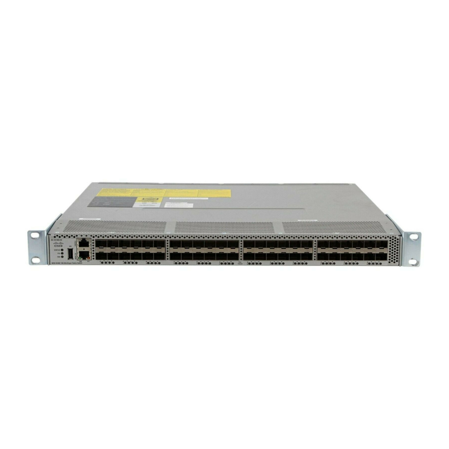
Cisco MDS 9100 Series Hardware Installation Manual

Cisco MDS 9100 Series Hardware Installation Manual

Hide thumbs Also See for MDS 9100 Series:
Table of Contents

Advertisement

Quick Links

Cisco MDS 9148S Multilayer Hardware Installation
Guide
July 2014
Cisco Systems, Inc.
www.cisco.com
Cisco has more than 200 offices worldwide.
Addresses, phone numbers, and fax numbers
are listed on the Cisco website at
www.cisco.com/go/offices.
Text Part Number: OL-29583-01

Advertisement

Table of Contents
loading
Need help?

Need help?

Do you have a question about the MDS 9100 Series and is the answer not in the manual?

Questions and answers

Subscribe to Our Youtube Channel

Summary of Contents for Cisco MDS 9100 Series

  • Page 1 Cisco MDS 9148S Multilayer Hardware Installation Guide July 2014 Cisco Systems, Inc. www.cisco.com Cisco has more than 200 offices worldwide. Addresses, phone numbers, and fax numbers are listed on the Cisco website at www.cisco.com/go/offices. Text Part Number: OL-29583-01...
  • Page 2 OR ITS SUPPLIERS HAVE BEEN ADVISED OF THE POSSIBILITY OF SUCH DAMAGES. Cisco and the Cisco logo are trademarks or registered trademarks of Cisco and/or its affiliates in the U.S. and other countries. To view a list of Cisco trademarks, go to this URL: www.cisco.com/go/trademarks.
  • Page 3: Table Of Contents

    Unpacking and Inspecting the Switch 2-4 Front-Facing Installation 2-6 Installing the Switch in a Cabinet with Insufficient Front Clearance 2-9 Installing Front Rack-Mount Brackets for Cabinets with 26 Inches or Greater of Rail Spacings 2-11 Cisco MDS 9148S Multilayer Switch Hardware Installation Guide OL-20185-01...
  • Page 4 Installing Power Supplies 2-22 Installing Power Supplies 2-23 Removing and Installing Fan Modules 2-23 Removing a Fan Module on the Cisco MDS 9148S Switch 2-23 Installing a Fan Module 2-25 Verifying the Fan Module 2-26 Connecting the Cisco MDS 9148S Switch...
  • Page 5 SFP Transceiver Specifications B-3 Cisco Fibre Channel SFP Transceivers B-4 General Specifications for Cisco Fibre Channel SFP Transceivers B-4 Environmental and Electrical Specifications for Cisco Fibre Channel SFP Transceivers Optical Specifications for Cisco CWDM SFP Transceivers B-5 Cable and Port Specifications...
  • Page 6 Contents Cisco MDS 9148S Multilayer Switch Hardware Installation Guide OL-20185-01...
  • Page 7: Audience

    Preface This preface describes the audience, organization, and conventions of the Cisco MDS 9148S Multilayer Switch Hardware Installation Guide. It also provides information on how to obtain related documentation. Audience To use this installation guide, you need to be familiar with electronic circuitry and wiring practices and preferably be an electronic or electromechanical technician.
  • Page 8: Document Conventions

    Voor vertalingen van de waarschuwingen die in deze publicatie verschijnen, kunt u het document Regulatory Compliance and Safety Information (Informatie over naleving van veiligheids- en andere voorschriften) raadplegen dat bij dit toestel is ingesloten. Cisco MDS 9148S Multilayer Switch Hardware Installation Guide OL-20185-01...
  • Page 9 Regulatory Compliance and Safety Information (Overholdelse av forskrifter og sikkerhetsinformasjon) som ble levert med denne enheten. Cisco MDS 9148S Multilayer Switch Hardware Installation Guide OL-20185-01...
  • Page 10: Related Documentation

    Safety Information (Efterrättelse av föreskrifter och säkerhetsinformation), vilket medföljer denna anordning. Related Documentation The documentation set for the Cisco MDS 9000 Family includes the following documents. To find a document online, use the Cisco MDS NX-OS Documentation Locator at: http://www.cisco.com/en/US/docs/storage/san_switches/mds9000/roadmaps/doclocater.htm Release Notes •...
  • Page 11: Compatibility Information

    Cisco MDS 9148S Multilayer Fabric Switch Quick Start Guide Software Installation and Upgrade • Cisco MDS 9000 NX-OS Release 6.2(x) and SAN-OS 3(x) Software Upgrade and Downgrade Guide • Cisco MDS 9000 Family Storage Services Interface Image Install and Upgrade Guide •...
  • Page 12: Cisco Data Center Network Manager

    Cisco DCNM Fundamentals Guide • Fabric Configuration Guide, Cisco DCNM for SAN • High Availability and Redundancy Configuration Guide, Cisco DCNM for SAN • Intelligent Storage Services Configuration Guide, Cisco DCNM for SAN • Inter-VSAN Routing Configuration Guide, Cisco DCNM for SAN •...
  • Page 13: Product Overview

    Intelligent diagnostics • Full compatibility with the Cisco MDS 9000 Family. The front of the Cisco MDS 9148S switch contains the LEDs, the console and management ports, and 48 16-Gbps Fibre Channel Ports. See Figure Cisco MDS 9148S Multilayer Switch Hardware Installation Guide...
  • Page 14 Ethernet port Power supply LED Fibre Channel ports FAN LED The rear of the Cisco MDS 9148S switch contains the redundant power supplies, the AC power receptacle, and the fans. See Figure Cisco MDS 9148S Multilayer Switch Hardware Installation Guide...
  • Page 15: Power Supplies

    Supported SFP+ Transceivers, page 1-12 Power Supplies The Cisco MDS 9148S switch supports only AC power supplies. Each power supply provides sufficient power to maintain switch operation in the event of a single power supply failure. Power supplies are hot swappable and can be individually replaced without disruption to the system.
  • Page 16: Fan Modules

    Cisco MDS 9148S switch has two fans. Caution The Cisco MDS 9148S switch has internal temperature sensors that can shut down the system if the temperature at different points within the chassis exceed certain safety thresholds. To be effective, the temperature sensors require the presence of airflow;...
  • Page 17 10/100/1000 Ethernet management port link Power supply LED 10/100/1000 Ethernet management port activity LED Fan module status LED Table 1-1 describes the front panel LEDs for the Cisco MDS 9148S switch. Table 1-1 Switching Module LEDs Status Description Switch status Green The Ethernet port is connected other device.
  • Page 18: Supported Sfp Transceivers

    LWL transceivers with LWL transceivers, and the cable must not exceed the stipulated cable length for reliable communications. For the list of supported SFP transceivers, see the Cisco MDS 9000 Family Release Notes for Cisco MDS NX-OS Releases. For more information about a specific Cisco SFP transceiver, see the “SFP Transceiver...
  • Page 19 Supported SFP+ Transceivers Note Use only Cisco SFP transceivers on the Cisco MDS 9148S switches. Each Cisco SFP transceiver is encoded with model information that enables the switch to verify that the SFP transceiver meets the requirements for the switch.
  • Page 20 Chapter 1 Product Overview Supported SFP+ Transceivers Cisco MDS 9148S Multilayer Switch Hardware Installation Guide 1-14 OL-20185-01...
  • Page 21: Installing The Cisco Mds 9148S Switch

    Removing and Installing Components, page 2-29 Note Before you install, operate, or service the system, read the Regulatory Compliance and Safety Information for the Cisco MDS 9000 Family for important safety information. IMPORTANT SAFETY INSTRUCTIONS Warning This warning symbol means danger. You are in a situation that could cause bodily injury. Before you work on any equipment, be aware of the hazards involved with electrical circuitry and be familiar with standard practices for preventing accidents.
  • Page 22: Preinstallation

    Chapter 2 Installing the Cisco MDS 9148S Switch Preinstallation Each new switch requires a license; see the Cisco MDS 9000 Family NX-OS Licensing Guide for Note instructions on installing a license. Preinstallation This section includes the following information: • Installation Options, page 2-16 •...
  • Page 23 Caution Avoid UPS types that use ferro-resonant technology. These UPS types can become unstable with systems such as the Cisco MDS 9000 Family, which can have substantial current draw fluctuations because of fluctuating data traffic patterns. • Ensure that circuits are sized according to local and national codes.
  • Page 24: Required Equipment

    Keep the shipping container in case the chassis requires shipping in the future. Note If you purchased Cisco support through a Cisco reseller, contact the reseller directly. If you purchased support directly from Cisco, contact Cisco Technical Support at this URL: http://www.cisco.com/en/US/support/tsd_cisco_worldwide_contacts.html...
  • Page 25: Front-Facing Installation

    For racks with square holes, insert the 12-24 cage nuts in position behind the mounting holes in the slider rails. Repeat with the other slider rail on the other side of the rack. Cisco MDS 9148S Multilayer Switch Hardware Installation Guide 2-19 OL-20185-01...
  • Page 26 Use the tape measure and level to verify that the rails are horizontal and at the same height. Figure 2-1 Installing the Slider Rails Figure 2-2 Installing the Notched Slider Rails Cisco MDS 9148S Multilayer Switch Hardware Installation Guide 2-20 OL-20185-01...
  • Page 27: Installing The Switch In A Cabinet With Insufficient Front Clearance

    Installing the Switch in a Cabinet with Insufficient Front Clearance This section describes how to use the rack-mount kit provided with the switch to install the Cisco MDS 9148S switch into a cabinet with insufficient front-facing clearance. The Cisco MDS 9148S switch is installed rear-facing to provide adequate clearance for the fiber-optic cables.
  • Page 28 Installing the Switch in a Cabinet with Insufficient Front Clearance cables is maintained. In these cabinets, the Cisco MDS 9148S switch is mounted backwards, with the fiber-optic cables facing toward the rear of the cabinet and the power supplies facing the front of the cabinet.
  • Page 29: Installing Front Rack-Mount Brackets For Cabinets With 26 Inches Or Greater Of Rail Spacings

    Repeat with the other front rack-mount bracket on the other side of the switch. Note The front rack-mount bracket does not align with all three holes in the Cisco MDS 9148S switch in this configuration. The two screws are adequate to hold the weight of the Cisco MDS 9148S switch.
  • Page 30: Installing Cisco Mds 9148S Switch Rear-Facing Into Cabinet

    Repeat with the other C bracket on the other side of the switch. Installing Cisco MDS 9148S Switch Rear-Facing into Cabinet To install a Cisco MDS 9148S switch rear-facing into a cabinet using the rack-mount kit provided with the switch (for cabinets with insufficient front-facing clearance), follow these steps:...
  • Page 31 (see Figure 2-4). For racks with square holes, first install the 12-24 cage nuts. Figure 2-4 Attaching the Cisco MDS 9148S Switch (Rear-Facing) to the Cabinet Rear cabinet mounting rails Front cabinet...
  • Page 32: Grounding The Switch

    A grounding pad with two threaded M4 holes is provided on the chassis for attaching a grounding lug. Figure 2-5 shows the system ground location on the Cisco MDS 9148S switch. Figure 2-5 Location of Switch Ground on the Cisco MDS 9148S Switch...
  • Page 33: Starting Up The Switch

    Verify that the power switches on both power supplies are off. Then plug the power cables into the power supplies and arrange the cables so that they cannot be accidentally pulled out. Cisco MDS 9148S Multilayer Switch Hardware Installation Guide 2-27...
  • Page 34 Starting Up the Switch Note Depending on the outlet receptacle on your power distribution unit, you may need the optional jumper power cord to connect the Cisco MDS 9148S switch to your outlet receptacle. See the “Jumper Power Cord” section on page 1-6.
  • Page 35: Removing And Installing Components

    During this procedure, wear grounding wrist straps to avoid ESD damage to the switch. Note The Cisco MDS 9148S Switch is only supported for operation with both power supplies and both fan modules installed, and with all fans working. With two power supplies installed, if one power supply fails, the system can continue to function normally on a single healthy power supply.
  • Page 36: Removing And Installing Ac Power Supplies

    Fan Module 1 (Fans 1 and 3) Power Supply 1 Removing and Installing AC Power Supplies This section provides instructions for removing and installing the AC power supplies for the Cisco MDS 9148S switch. Removing Power Supplies To remove a AC power supply, follow these steps: Turn the power switch to the off (0) position on the power supply that you are removing.
  • Page 37: Removing And Installing Fan Modules

    Caution The Cisco MDS 9000 Family has internal temperature sensors that can shut down the system if the temperature at different points within the chassis exceed certain safety thresholds. To be effective, the temperature sensors require the presence of airflow;...
  • Page 38: Installing A Fan Module

    Position the fan module with the LED oriented away from the back of the switch. Figure 2-7 shows the fan module for the Cisco MDS 9148S switch. Step 2 Slide the fan module into the switch until it clicks into place.
  • Page 39: Verifying The Fan Module

    The transceiver label generally lists the model and wavelength. Note If you purchased this product through a Cisco reseller, contact the reseller directly for technical support. If you purchased this product directly from Cisco, contact Cisco Technical Support at this URL: http://www.cisco.com/en/US/support/tsd_cisco_worldwide_contacts.html...
  • Page 40 Chapter 2 Installing the Cisco MDS 9148S Switch Removing and Installing Components Cisco MDS 9148S Multilayer Switch Hardware Installation Guide 2-34 OL-20185-01...
  • Page 41: Connecting The Cisco Mds 9148S Switch

    Fibre Channel ports (Supervisor and Switching Modules)— Fibre Channel ports that you can use to connect to the SAN, or for in-band management. This chapter describes how to connect the various components of the Cisco MDS 9148S switch, and it includes the following information: •...
  • Page 42: Connecting The Console Port To A Pc

    Figure 1-1 Connecting the Console Cable Connecting the Console Port to a PC You can connect the console port to a PC serial port for local administrative access to the Cisco MDS 9148S switch. Note The PC must support VT100 terminal emulation. The terminal emulation software—frequently a PC application such as HyperTerminal Plus—makes communication between the Cisco MDS 9148S switch...
  • Page 43: Connecting A Modem To A Console Port

    Default initialization string (ATE0Q1&D2&C1S0=1\015) if previously configured Note For instructions on how to change these settings, see the Cisco Fabric Manager Fundamentals Configuration Guide for instructions on how to change these settings. To connect the console port to a modem after the switch is powered on, follow these steps: Step 1 Ensure that the system has completed booting and the system image is running.
  • Page 44: Connecting The 10/100 Ethernet Management Port

    Cisco Fabric Manager Fundamentals Configuration Guide and the Cisco NX-OS Fundamentals Configuration Guide. The Cisco MDS 9148S switch supports both Fibre Channel and Gigabit Ethernet protocols for SFP transceivers. Each transceiver must match the transceiver on the other end of the cable, and the cable must not exceed the stipulated cable length for reliable communications.
  • Page 45: Installing An Sfp Transceiver

    Connecting to a Fibre Channel Port Note Use only Cisco SFP transceivers on the Cisco MDS 9148S switch. Each Cisco SFP transceiver is encoded with model information that enables the switch to verify that the SFP transceiver meets the requirements for the switch.
  • Page 46: Removing An Sfp Transceiver

    Installing a Cable into an SFP Transceiver Caution To prevent possible damage to the cable or transceiver, install the transceiver in the port before installing the cable in the transceiver. Cisco MDS 9148S Multilayer Switch Hardware Installation Guide 1-40 OL-20185-01...
  • Page 47: Removing A Cable From An Sfp Transceiver

    Caution If the cable does not install easily, ensure it is correctly oriented before continuing. For instructions on verifying connectivity, see the Cisco Fabric Manager Fundamentals Configuration Guide and the Cisco NX-OS Fundamentals Configuration Guide. Removing a Cable from an SFP Transceiver Caution When pulling a cable from a transceiver, grip the body of the connector.
  • Page 48: Maintaining Sfp Transceivers And Fiber-Optic Cables

    • Inspect routinely for dust and damage. If damage is suspected, clean and then inspect fiber ends under a microscope to determine if damage has occurred. Cisco MDS 9148S Multilayer Switch Hardware Installation Guide 1-42 OL-20185-01...
  • Page 49: Cabinet And Rack Installation

    Cisco MDS 9000 Family Telco and EIA Shelf Bracket, page 1-45 Cabinet and Rack Requirements This section provides the Cisco MDS 9000 Family requirements for the following types of cabinets and racks, assuming an external ambient air temperature range of 0 to 40°C: •...
  • Page 50: Requirements Specific To Perforated Cabinets

    • We recommend that the roof be perforated with at least 20 percent open area, unless the cabinet only contains Cisco MDS 9148S switch, in which case the roof does not have to be perforated. • We recommend an open or perforated cabinet floor to enhance cooling but it is not required.
  • Page 51: Requirements Specific To Solid-Walled Cabinets

    The optional Telco and EIA Shelf Bracket Kit (part number DS-SHELF=) can temporarily or permanently support the Cisco MDS 9148S switch during installation. Once the front rack-mount brackets are securely attached to the rack-mounting rails, the shelf bracket can be removed.
  • Page 52 This optional kit is not provided with the switch; to order the kit, contact your switch supplier. This section describes the procedure for installing a Cisco MDS 9148S switch in a rack or cabinet using the optional Telco and EIA Shelf Bracket Kit. This section includes the following information: •...
  • Page 53: Installing The Shelf Bracket Kit Into A Two-Post Telco Rack

    Chapter 1 Cabinet and Rack Installation Cisco MDS 9000 Family Telco and EIA Shelf Bracket Before Installing the Shelf Brackets Before installing the shelf brackets, inspect the contents of your kit. Table 1-1 lists the contents of the shelf bracket kit.
  • Page 54 Chapter 1 Cabinet and Rack Installation Cisco MDS 9000 Family Telco and EIA Shelf Bracket To install the shelf brackets in a Telco rack, follow these steps: Step 1 Position a shelf bracket inside a rack-mounting rail as shown in...
  • Page 55: Installing The Shelf Bracket Kit Into A Four-Post Eia Rack

    Chapter 1 Cabinet and Rack Installation Cisco MDS 9000 Family Telco and EIA Shelf Bracket Installing the Shelf Bracket Kit into a Four-Post EIA Rack Figure 1-2 shows the installation of the shelf bracket kit into a four-post EIA rack.
  • Page 56: Installing The Switch On The Shelf Brackets

    Note Before you install, operate, or service the system, refer to the Regulatory Compliance and Safety Information for the Cisco MDS 9000 Family for important safety information. To install the switch on top of the shelf brackets, follow these steps:...
  • Page 57: Removing The Shelf Bracket Kit (Optional

    Removing the Shelf Bracket Kit (Optional) The shelf bracket kit can be removed after the Cisco MDS 9148S switch has been installed in a four-post EIA rack, and both front rack-mount brackets and both C brackets are securely attached to the rack-mounting rails.
  • Page 58 Chapter 1 Cabinet and Rack Installation Cisco MDS 9000 Family Telco and EIA Shelf Bracket Cisco MDS 9148S Multilayer Switch Hardware Installation Guide 1-52 OL-20185-01...
  • Page 59: B Technical Specifications

    C H A P T E R Technical Specifications This appendix includes the following technical specifications for the Cisco MDS 9148S switch: • Switch Specifications, page 1-53 • Power Specifications, page 1-54 • SFP Transceiver Specifications, page 1-56 Switch Specifications Table 1-1 lists the environmental specifications for the Cisco MDS 9148S switch.
  • Page 60: Power Specifications

    Connection Guidelines for AC-Powered Systems, page 1-55 General Power Supply Specifications Table 1-3 lists the specifications for the Cisco MDS 9148S switch AC input power supply. Table 1-3 Cisco MDS 9148S Switch AC Input Power Supply Specifications AC Input Power Supply...
  • Page 61: Connection Guidelines For Ac-Powered Systems

    To prevent a loss of input power, ensure that the total maximum load on each circuit supplying the power supply is within the current ratings of the wiring and breakers. Connection Guidelines for AC-Powered Systems For connecting the Cisco MDS 9148S switch AC power supplies to the site power source, follow these basic guidelines: •...
  • Page 62: Sfp Transceiver Specifications

    SFP Transceiver Specifications SFP Transceiver Specifications The Cisco MDS 9148S switch is compatible with SFP transceivers and cables that have LC connectors. Each transceiver must match the transceiver on the other end of the cable in terms of wavelength, and the cable must not exceed the stipulated cable length for reliable communications.
  • Page 63 150 m (492 ft) (OM2) 380 m (1247 ft) (OM3) 400 m (1312 ft) (OM4) DS-SFP-FC16G-L 1310 14.025 10 km (6.2 mi) 10 km (6.2 mi) 4.25 10 km (6.2 mi) Cisco MDS 9148S Multilayer Switch Hardware Installation Guide 1-57 OL-20185-01...
  • Page 64 SFP+ Operating Storage DS-SFP-FC16G-SW 40°C 0°C 85°C -40°C DS-SFP-FC16G-LW 40°C 0°C 85°C -40°C General Specifications for Cisco Fibre Channel 8-Gbps SFP+ Transceivers Table 1-9 summarizes cabling specifications for 8 Gbps. Cisco MDS 9148S Multilayer Switch Hardware Installation Guide 1-58 OL-20185-01...
  • Page 65 10 km (6.2 mi) 4.250 10 km (6.2 mi) 8.500 10 km (6.2 mi) DS-SFP-FC8G-ER 1550 2.125 40 km (24.85 mi) 4.250 40 km (24.85 mi) 8.500 40 km (24.85 mi) Cisco MDS 9148S Multilayer Switch Hardware Installation Guide 1-59 OL-20185-01...
  • Page 66: Optical Specifications For Cisco Cwdm Sfp Transceivers

    CWDM SFP transceivers. CWDM SFP transceivers have an optical link budget of 28 decibels (db). Note The parameters are specified over temperature and at end of life unless otherwise noted. Cisco MDS 9148S Multilayer Switch Hardware Installation Guide 1-60 OL-20185-01...
  • Page 67 PRBS case temp. –1) λ Receiver optical 1450 1620 input wavelength Transmitter extinction ratio Dispersion penalty at 60 km Dispersion penalty @ 1.25 Gbps at 100 km @ 2.12 Gbps Cisco MDS 9148S Multilayer Switch Hardware Installation Guide 1-61 OL-20185-01...
  • Page 68 Chapter 1 Technical Specifications Cisco MDS 9148S Multilayer Switch Hardware Installation Guide 1-62 OL-20185-01...
  • Page 69: C Cable And Port Specifications

    Additional cables and adapters can be ordered from your customer service representative. Note If you purchased this product through a Cisco reseller, contact the reseller directly for technical support. If you purchased this product directly from Cisco, contact Cisco Technical Support at this URL: http://www.cisco.com/cisco/web/support/index.html.
  • Page 70: Console Port

    (depending on your computer serial port) to connect the console port to a computer running terminal emulation software. Console Port Pinouts Table 1-1 lists the pinouts for the console port on the Cisco MDS 9148S Switch. Table 1-1 Console Port Pinouts Signal 1.
  • Page 71: Connecting The Console Port To A Computer Using The Db-9 Adapter

    Port Mode Signaling and Pinouts with DB-9 Adapter RJ-45 to DB-9 Console Terminal Console Port RJ-45 to RJ-45 Rollover Cable Adapter Device Signal RJ-45 Pins RJ-45 Pin DB-9 Pin Signal Cisco MDS 9148S Multilayer Switch Hardware Installation Guide 1-65 OL-20185-01...
  • Page 72: Mgmt 10/100 Ethernet Port

    1 RD+ 2 RD- 2 RD- 3 TD+ 3 TD+ 6 TD- 6 TD- 4 NC 4 NC 5 NC 5 NC 7 NC 7 NC 8 NC 8 NC Cisco MDS 9148S Multilayer Switch Hardware Installation Guide 1-66 OL-20185-01...
  • Page 73: Supported Power Cords And Plugs

    Orders delivered to Argentina, Brazil, and Japan must have the appropriate power cord ordered with the system. Figure 1-3 shows the supported plugs for the Cisco MDS 9100 Series power supplies. Cisco MDS 9148S Multilayer Switch Hardware Installation Guide 1-67...
  • Page 74: Jumper Power Cord

    C14 and C15 connectors on the optional jumper power cord for the Cisco MDS 9148S Switch. The C15 connector connects into the C14 inlet on the Cisco MDS 9148S Switch power supply, while the C14 connector connects into the C13 receptacle of a power distribution unit for a cabinet.
  • Page 75 Chapter 1 Cable and Port Specifications Supported Power Cords and Plugs Figure 1-4 Connectors on Jumper Power Cord for Cisco MDS 9148S Switch Cisco MDS 9148S Multilayer Switch Hardware Installation Guide 1-69 OL-20185-01...
  • Page 76 Chapter 1 Cable and Port Specifications Supported Power Cords and Plugs Cisco MDS 9148S Multilayer Switch Hardware Installation Guide 1-70 OL-20185-01...
  • Page 77: D Site Planning And Maintenance Records

    • Chassis and Network Information, page 1-74 Note For information about how to query the switch for configuration information, see the Cisco NX-OS Fundamentals Configuration Guide. Site Preparation Checklist Planning the location and layout of your equipment rack or wiring closet is essential for successful switch operation, ventilation, and accessibility.
  • Page 78 • levels 1. Verify that the power supply installed in the chassis has a dedicated AC source circuit. 2. UPS = uninterruptible power supply. 3. RFI = radio frequency interference. Cisco MDS 9148S Multilayer Switch Hardware Installation Guide 1-72 OL-20185-01...
  • Page 79: Contact And Site Information

    Table 1-2 Contact and Site Information Contact person Contact phone Contact E-Mail Building/site name Data center location Floor location Address (line 1) Address (line 2) City State Zip code Country Cisco MDS 9148S Multilayer Switch Hardware Installation Guide 1-73 OL-20185-01...
  • Page 80: Chassis And Network Information

    Chassis Serial Number ______________________________________________________________ Product Number ______________________________________________________________ Table 1-3 Network-Related Information Switch IP address Switch IP netmask Host name Domain name IP broadcast address Gateway/router address DNS address Modem telephone number Cisco MDS 9148S Multilayer Switch Hardware Installation Guide 1-74 OL-20185-01...

This manual is also suitable for:

Mds 9148sDs-c9148s48pk9

Table of Contents