Table of Contents
Advertisement
Quick Links
Advertisement
Table of Contents

Subscribe to Our Youtube Channel
Summary of Contents for ACL Mini MIDI
- Page 1 Mini MIDI User Manual Software Version 1.1 Documentation Version 17.11.2020...
- Page 2 MANUFACTURER’S WARRANTY The warranty period is valid for one year from the day of purchase. Audiophile Circuits League (ACL) warrants this product against defects in material and workmanship. The warranty will expire in case of failure or damage caused by: •...
-
Page 3: Table Of Contents
TABLE OF CONTENTS: 1. INTRODUCTION........................4 2. INSTALLATION.........................5 3. OPERATING ELEMENTS....................6 3.1 FRONT PANEL......................6 3.2 BACK...........................7 4. GETTING STARTED......................8 4.1 SETTING THE MIDI CHANNEL..................9 4.2 MODES OF OPERATION...................9 5. CALIBRATION MODE.....................11 6. TECHNICAL SPECIFICATIONS..................12... -
Page 4: Introduction
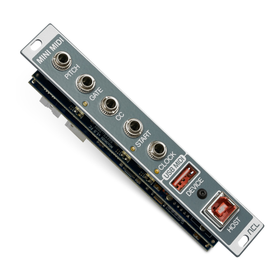
1. INTRODUCTION The MINI MIDI is a USB MIDI to CV/GATE interface built in a small, space saving Eurorack module. It converts a monophonic MIDI Note, one selectable MIDI CONTROL CHANGE (or NOTE ON VELOCITY or CHANNEL´S PRESSURE), MIDI CLOCK and START/STOP to corresponding Eurorack compatible CV, GATE, Clock and Trigger signals. -
Page 5: Installation
2. INSTALLATION ⚠ WARNING Always turn the Eurorack power supply off and unplug the power cord before plugging the Eurorack power cable to your module. When attaching the Eurorack power cable, please be careful not to touch the terminal part. Connect to the Eurorack's system power supply using the supplied Eurorack power cable. -
Page 6: Operating Elements
3. OPERATING ELEMENTS 3.1 FRONT PANEL OUTPUTS: • PITCH: CV output (1V / Octave, -3V to 7V) • GATE: Active high Gate output (10V) • CC: CV output for a MIDI CC, Note On Velocity or Channel´s Pressure (0V to 5V) •... -
Page 7: Back
3.2 BACK POWER CONNECTOR Connect a 16-pin Eurorack power cable. JUMPER SETTINGS The PITCH and GATE outputs can be connected to Pitch and Gate signals on the Eurorack power connector. • Gate: Set to connect Gate output to Gate signal on power connector. •... -
Page 8: Getting Started
Before applying power to the module, select the MIDI controller number to be mapped to the CC output by setting the DIP switches on the back of the Mini MIDI (see table 1). Most commonly used MIDI Control Change Numbers are implemented. -
Page 9: Setting The Midi Channel
Mini MIDI. USB Host to CV/Gate When a USB MIDI Host is connected to the USB HOST Port on the Mini MIDI, MIDI messages from the Host will be directly converted and mapped to their corresponding outputs on the Mini MIDI. - Page 10 Implemented MIDI messages Regardless of which USB Port is being used, the Mini MIDI listens to Channel Voice Messages and System Real-Time Messages like MIDI Clock and START/STOP/CONTINUE. 2 lists all MIDI messages implemented in the Mini MIDI. MIDI Channel Voice Messages...
-
Page 11: Calibration Mode
(1 mVmess). Calibration procedure 1. Connect the voltage meter to the PITCH output of the Mini MIDI. You can insert a patch cable into the PITCH output and connect the positive probe of the voltage meter to the tip of the patch cable connector and the negative probe of the voltage meter to the sleeve of the patch cable connector. -
Page 12: Technical Specifications
6. TECHNICAL SPECIFICATIONS DAC resolution (PITCH, CC): 16 bit Pitch Output range (1V / Octave): -3 V to 7 V Gate Output: 0 V / 10 V MIDI CC Output: 0 V to 5 V MIDI Start / Stop: Active High (5 V) MIDI Clock: Rising edge (5 V) USB MIDI Host Interface output current: up to 500 mA Current Draw:...
Need help?
Do you have a question about the Mini MIDI and is the answer not in the manual?
Questions and answers