Table of Contents
Advertisement
Quick Links
Manual, Tool Changer, QC-50
Document #9620-20-B-50 Tool Changer-04
B. Base Tool Changer ..................................................................................................................B-3
QC-50 Series-Robotic Tool Changer ........................................................................................B-3
1.
Product Overview ..................................................................................................................B-3
1.1
Master Plate Assembly ............................................................................................................. B-4
1.2
Tool Plate Assembly .................................................................................................................. B-5
1.3
Optional Modules ...................................................................................................................... B-5
2.
Installation .............................................................................................................................B-6
2.1
Master Interface ......................................................................................................................... B-7
2.2
Master Plate Installation ........................................................................................................... B-8
2.3
Master Plate Removal ............................................................................................................... B-8
2.4
Tool Interface ............................................................................................................................. B-9
2.5
Tool Plate Installation ............................................................................................................. B-10
2.6
Tool Plate Removal ................................................................................................................. B-10
2.7
Optional Module with J16 Pattern Installation .......................................................................B-11
2.8
Optional Module with J16 Pattern Removal ...........................................................................B-11
2.9
Optional K Series Module Installation ................................................................................... B-12
2.10 Optional K Series Module Removal ....................................................................................... B-12
2.11 Pneumatic Connections and Valve Requirements ............................................................... B-13
2.11.1 Valve Requirements and Connections for the Locking Mechanism ..............................B-13
2.12 Electrical Connections ............................................................................................................ B-14
2.12.1 PNP Type Lock and Unlock Sensors .............................................................................B-14
2.12.2 NPN Type Lock and Unlock Sensors ............................................................................B-14
3.
Operation .............................................................................................................................B-15
3.1
Conditions for Coupling ......................................................................................................... B-16
3.2
Fail-Safe Operation ................................................................................................................. B-17
3.3
Conditions for Uncoupling ..................................................................................................... B-18
3.4
3.5
Tool Storage Considerations ................................................................................................. B-19
4.
Maintenance .........................................................................................................................B-20
4.1
Preventive Maintenance ......................................................................................................... B-20
4.2
Cleaning and Lubrication of the Locking Mechanism and Alignment Pins ....................... B-21
4.3
Pin Block Inspection and Cleaning ....................................................................................... B-23
Pinnacle Park • 1031 Goodworth Drive • Apex, NC 27539 • Tel: 919.772.0115 • Fax: 919.772.8259 •
Table of Contents
B-1
• Email:
www.ati-ia.com
info@ati-ia.com
Advertisement
Table of Contents

Related Manuals for ATI Technologies QC‑50 Series


Summary of Contents for ATI Technologies QC‑50 Series
-
Page 1: Table Of Contents
Manual, Tool Changer, QC‑50 Document #9620‑20‑B‑50 Tool Changer‑04 Table of Contents B. Base Tool Changer ........................B-3 QC-50 Series—Robotic Tool Changer ..................B-3 Product Overview ........................B-3 Master Plate Assembly ......................B-4 Tool Plate Assembly ........................B-5 Optional Modules ........................B-5 Installation ..........................B-6 Master Interface ......................... - Page 2 Manual, Tool Changer, QC‑50 Document #9620‑20‑B‑50 Tool Changer‑04 Troubleshooting and Service Procedures ................B-24 Troubleshooting Procedures ....................B-24 Service Procedures ......................... B-25 5.2.1 Lock and Unlock Sensor Replacement .................B-25 5.2.2 Rubber Bushing Replacement ..................B-26 5.2.3 Seal Inspection and Replacement .................B-27 5.2.4 Alignment Pin Replacement ..................B-28 Serviceable Parts ........................B-30 QC-50 Master Plates ........................
-
Page 3: Base Tool Changer
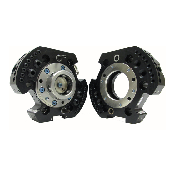
Manual, Tool Changer, QC‑50 Document #9620‑20‑B‑50 Tool Changer‑04 B. Base Tool Changer QC-50 Series—Robotic Tool Changer 1. Product Overview ATI Tool Changers enhance the versatility of a robot by enabling the use of multiple customer tools, such as: grippers, vacuum cup tooling, pneumatic and electric motors, weld guns, and more. The Tool Changer consists of a Master plate, which is attached to the robot arm, and a Tool plate, which is attached to customer tooling. -
Page 4: Master Plate Assembly
Manual, Tool Changer, QC‑50 Document #9620‑20‑B‑50 Tool Changer‑04 1.1 Master Plate Assembly The Master plate assembly includes an anodized aluminum body, a hardened stainless‑steel locking 1.1). The Master plate has (4) flats for mounting mechanism, and hardened steel alignment pins (see Figure optional modules with a J16 pattern. -
Page 5: Tool Plate Assembly
Manual, Tool Changer, QC‑50 Document #9620‑20‑B‑50 Tool Changer‑04 1.2 Tool Plate Assembly The Tool plate assembly includes an anodized aluminum body and a hardened stainless‑steel bearing race. The Tool plate has (4) flats for mounting optional modules with a J16 pattern. Flat “C” also has a mounting pattern for a K series module. -
Page 6: Installation
Manual, Tool Changer, QC‑50 Document #9620‑20‑B‑50 Tool Changer‑04 2. Installation All fasteners used to mount the Tool Changer to the robot and to customer’s tooling should be tightened to a torque value as indicated in Table 2.1. WARNING: Do not use lock washers under the head of the mounting fasteners or allow the mounting fasteners to protrude above the mating surfaces of the Master and Tool plates. -
Page 7: Master Interface
Manual, Tool Changer, QC‑50 Document #9620‑20‑B‑50 Tool Changer‑04 2.1 Master Interface The Master plate is typically attached to the robot arm. An interface plate can adapt the Master plate to a specific robot arm. Alignment features (dowel holes and bosses) accurately position and bolt holes secure the Master plate to the robot arm or an interface plate. -
Page 8: Master Plate Installation
Manual, Tool Changer, QC‑50 Document #9620‑20‑B‑50 Tool Changer‑04 2.2 Master Plate Installation Tools required: 6 mm hex key, toque wrench Supplies required: Clean rag, Loctite ® 1. Clean the mounting surfaces. 2. Align the dowel pins to the corresponding holes in the Master plate. Secure the Master plate to the robot arm or interface plate with customer supplied (6) M8 socket head cap screws using a 6 mm hex key. -
Page 9: Tool Interface
Manual, Tool Changer, QC‑50 Document #9620‑20‑B‑50 Tool Changer‑04 2.4 Tool Interface The Tool plate is attached to the customer’s tooling. An interface plate can adapt the Tool plate to customer tooling. Alignment features (dowel holes and a recess) accurately position and bolt holes to secure the Tool plate to customer tooling. -
Page 10: Tool Plate Installation
Manual, Tool Changer, QC‑50 Document #9620‑20‑B‑50 Tool Changer‑04 2.5 Tool Plate Installation Tools required: 6 mm hex key, toque wrench Supplies required: Clean rag, Loctite 242 1. Clean the mounting surfaces. 2. Align the dowel pins to the corresponding holes in the Tool plate. Secure the Tool plate to the tool interface plate or customer tooling with customer supplied customer supplied (6) M8 socket head cap screws using a 6 mm hex key. -
Page 11: Optional Module With J16 Pattern Installation
Manual, Tool Changer, QC‑50 Document #9620‑20‑B‑50 Tool Changer‑04 2.7 Optional Module with J16 Pattern Installation Tools required: 3 mm hex key, toque wrench Supplies required: Clean rag, Loctite 222 1. Place the Tool in a secure location. 2. Uncouple the Master and Tool plates. 3. -
Page 12: Optional K Series Module Installation
Manual, Tool Changer, QC‑50 Document #9620‑20‑B‑50 Tool Changer‑04 2.9 Optional K Series Module Installation Tools required: 2.5 mm hex key, torque wrench Supplies required: Clean rag, Loctite 222 1. If the Tool Changer is in service, place the Tool in a secure location. 2. -
Page 13: Pneumatic Connections And Valve Requirements
Manual, Tool Changer, QC‑50 Document #9620‑20‑B‑50 Tool Changer‑04 2.11 Pneumatic Connections and Valve Requirements The air supply used for coupling and uncoupling the Tool Changer should be clean, dry, and non‑lubricated. A supply pressure in the range of 60 to 100 psi is acceptable for operation of the locking mechanism, with a setting of 80 psi suggested. -
Page 14: Electrical Connections
Manual, Tool Changer, QC‑50 Document #9620‑20‑B‑50 Tool Changer‑04 2.12 Electrical Connections The Tool Changer is available with integrated lock/unlock sensors. If sensors are not required, plugs are provided to seal the locking mechanism. 2.12.1 PNP Type Lock and Unlock Sensors These sensors are used on 9120‑050AM‑0‑0‑0‑0‑SB‑E and 9120‑050AM‑0‑0‑0‑0‑SB1. -
Page 15: Operation
Manual, Tool Changer, QC‑50 Document #9620‑20‑B‑50 Tool Changer‑04 3. Operation The Master plate locking mechanism is pneumatically driven to couple and uncouple with the Tool plate bearing race. CAUTION: Operation of the Tool Changer is dependent on maintaining an air pressure of 60 to 100 psi (4.1 - 6.9 bar). -
Page 16: Conditions For Coupling
Manual, Tool Changer, QC‑50 Document #9620‑20‑B‑50 Tool Changer‑04 3.1 Conditions for Coupling The following conditions should be considered when operating the Tool Changer. For more details about programming the robot, refer to the Operation section of the Control/Signal Module Manual. CAUTION: Do not attempt to couple the Tool Changer when in locked position. -
Page 17: Fail-Safe Operation
Manual, Tool Changer, QC‑50 Document #9620‑20‑B‑50 Tool Changer‑04 6. A sufficient delay must be programmed between locking valve actuation and robot motion so that the locking process is complete before moving the robot. If equipped with Lock and Unlock sensors, the Lock signal should read “ON”... -
Page 18: Conditions For Uncoupling
Manual, Tool Changer, QC‑50 Document #9620‑20‑B‑50 Tool Changer‑04 3.3 Conditions for Uncoupling Refer to your Air/Valve Adapter and/or Control/Signal Module Manual’s Operation section for operation during coupling/uncoupling. 1. Move the robot to position the Tool plate in the tool stand. The position for coupling and uncoupling are the same. -
Page 19: Tool Storage Considerations
Manual, Tool Changer, QC‑50 Document #9620‑20‑B‑50 Tool Changer‑04 3.5 Tool Storage Considerations NOTICE: Tool stand design is critical to the operation of the Tool Changer. Improperly designed tool stands can cause jamming and excessive wear of the Tool Changer components. Tool plates with customer tooling attached may be stored in a tool stand. -
Page 20: Maintenance
Manual, Tool Changer, QC‑50 Document #9620‑20‑B‑50 Tool Changer‑04 4. Maintenance WARNING: Do not perform maintenance or repair(s) on the Tool Changer or modules unless the Tool is safely supported or placed in the tool stand, all energized circuits (e.g. electrical, air, water, etc.) are turned off, pressurized connections are purged and power is discharged from circuits in accordance with the customer specific safety practices and policies. -
Page 21: Cleaning And Lubrication Of The Locking Mechanism And Alignment Pins
Manual, Tool Changer, QC‑50 Document #9620‑20‑B‑50 Tool Changer‑04 4.2 Cleaning and Lubrication of the Locking Mechanism and Alignment Pins ® Supplies required: Clean rag, MobilGrease XHP222 Special Grease 1. Place the Tool in a secure location. 2. Uncouple the Master and Tool plates. 3. - Page 22 Manual, Tool Changer, QC‑50 Document #9620‑20‑B‑50 Tool Changer‑04 6. Check each ball bearing to make sure it moves freely in the male coupling. Additional cleaning may be necessary to free up any ball bearings that are sticking in place. Figure 4.3—Check Ball Bearing Movement 7.
-
Page 23: Pin Block Inspection And Cleaning
Manual, Tool Changer, QC‑50 Document #9620‑20‑B‑50 Tool Changer‑04 4.3 Pin Block Inspection and Cleaning Tools required: Nylon Brush (ATI Part Number 3690‑0000064‑60) 1. Place the Tool in a secure location. 2. Uncouple the Master and Tool plates. 3. Turn off and de‑energize all energized circuits (e.g. electrical, air, water, etc.). 4. -
Page 24: Troubleshooting And Service Procedures
Manual, Tool Changer, QC‑50 Document #9620‑20‑B‑50 Tool Changer‑04 5. Troubleshooting and Service Procedures The following section provides troubleshooting and service information to help diagnose conditions and repair the control/signal module. Tool Changer WARNING: Do not perform maintenance or repair(s) on the Tool Changer or modules unless the Tool is safely supported or placed in the tool stand, all energized circuits (e.g. -
Page 25: Service Procedures
Manual, Tool Changer, QC‑50 Document #9620‑20‑B‑50 Tool Changer‑04 5.2 Service Procedures Component replacement procedures are provided in the following section. 5.2.1 Lock and Unlock Sensor Replacement Parts required: Refer to Section 6—Serviceable Parts Tools required: 2.5 mm hex key, torque wrench 1. -
Page 26: Rubber Bushing Replacement
Manual, Tool Changer, QC‑50 Document #9620‑20‑B‑50 Tool Changer‑04 5.2.2 Rubber Bushing Replacement Parts required: Refer to Section 6—Serviceable Parts Tools required: needle nose pliers 1. Place the Tool in a secure location. 2. Uncouple the Master and Tool plates. 3. Turn off and de‑energize all energized circuits; for example, electrical, air, water, etc. If required, fully disconnect these circuits. -
Page 27: Seal Inspection And Replacement
Manual, Tool Changer, QC‑50 Document #9620‑20‑B‑50 Tool Changer‑04 5.2.3 Seal Inspection and Replacement Parts required: Refer to Section 6—Serviceable Parts The seal protects the electrical connection between the Master and Tool module. If the seal becomes worn or damaged, replace the seal. 1. -
Page 28: Alignment Pin Replacement
Manual, Tool Changer, QC‑50 Document #9620‑20‑B‑50 Tool Changer‑04 5.2.4 Alignment Pin Replacement Parts required: Refer to Section 6—Serviceable Parts Tools required: 2.5 mm and 3 mm hex key, torque wrench Supplies required: Clean rag, MobilGrease XHP222, Loctite 242 1. Place the Tool in a secure location. 2. - Page 29 Manual, Tool Changer, QC‑50 Document #9620‑20‑B‑50 Tool Changer‑04 6. Another approach would be to use the access hole in the back side of the Master plate. If not Removal. Use a already removed, remove the Master plate refer to Section 2.3—Master Plate 3 mm hex key to remove the alignment pin from the back side of the Master plate by turning the alignment pin clockwise to drive the pin out the front of the plate.
-
Page 30: Serviceable Parts
Manual, Tool Changer, QC‑50 Document #9620‑20‑B‑50 Tool Changer‑04 6. Serviceable Parts 6.1 QC-50 Master Plates Table 5.2—Master Plate Item No. Qty Part Number Description 9120-050AM-0-0-0-0-E QC-50 Master Assembly, BSPP, M5 Ports 3700-20-1373 Mono Alignment Pin, QC-100, A2 4010-0000009-02 M5 Rubber Bushing, Nitrile, Light-5 4010-0000021-01 1/4”... -
Page 31: Tool Plate
Manual, Tool Changer, QC‑50 Document #9620‑20‑B‑50 Tool Changer‑04 6.2 QC-50 Tool Plate Table 5.3—Tool Plate Item No. Part Number Description 9120-050BT-0-0-0-0-E QC-50 Tool Assembly, BSPP and M5 Pinnacle Park • 1031 Goodworth Drive • Apex, NC 27539 • Tel: 919.772.0115 • Fax: 919.772.8259 • •... -
Page 32: Specifications
Manual, Tool Changer, QC‑50 Document #9620‑20‑B‑50 Tool Changer‑04 7. Specifications Table 5.4—Troubleshooting Specification Values Description Recommended Max Payload 110 lbs. (50kg) The mass attached to the Tool Changer. -20–150°F Operating Temperature Range Optimal operating temperature (-30–66°C) Locking mechanism supply pressure operating 60–100 psi range. -
Page 33: Drawings
Manual, Tool Changer, QC‑50 Document #9620‑20‑B‑50 Tool Changer‑04 8. Drawings 8.1 QC-50 Tool Changer with Standard Tool Plate Pinnacle Park • 1031 Goodworth Drive • Apex, NC 27539 • Tel: 919.772.0115 • Fax: 919.772.8259 • • Email: www.ati‑ia.com info@ati‑ia.com B-33... - Page 34 Manual, Tool Changer, QC‑50 Document #9620‑20‑B‑50 Tool Changer‑04 Pinnacle Park • 1031 Goodworth Drive • Apex, NC 27539 • Tel: 919.772.0115 • Fax: 919.772.8259 • • Email: www.ati‑ia.com info@ati‑ia.com B-34...
- Page 35 Manual, Tool Changer, QC‑50 Document #9620‑20‑B‑50 Tool Changer‑04 Pinnacle Park • 1031 Goodworth Drive • Apex, NC 27539 • Tel: 919.772.0115 • Fax: 919.772.8259 • • Email: www.ati‑ia.com info@ati‑ia.com B-35...
Need help?
Do you have a question about the QC‑50 Series and is the answer not in the manual?
Questions and answers