
Related Manuals for ATI Technologies QC-5


Summary of Contents for ATI Technologies QC-5
- Page 1 Robotic Tool Changers QC-5 through QC-27 Manual Document #: 9610-20-2254 Engineered Products for Robotic Productivity Pinnacle Park • 1041 Goodworth Drive • Apex, NC 27539 USA • Tel: 919.772.0115 • Fax: 919.772.8259 • www.ati-ia.com...
-
Page 2: Foreword
Manual, Robotic Tool Changer, QC-5 through QC-27 Document #9610-20-2254-09 Foreword This manual contains basic information applicable to all ATI robotic Tool Changers. Certain models have their own manuals that contain more detailed information. Also, additional information about electrical, pneumatic, fluid, high- power, and high-current modules and other options are available in other manuals and documents. -
Page 3: Table Of Contents
Tool Plate Installation ......................... 20 Tool Plate Removal ........................20 Optional Module Installation ...................... 21 3.7.1 QC-5 and QC-11 Simple Electrical Module Installation ............ 21 3.7.2 QC-5 and QC-11 Simple Electrical Module Removal ............21 3.7.3 QC-5 and QC-11 Master Electrical Module Installation ............ 22 3.7.4... - Page 4 Models QC-21 Serviceable Parts ....................60 Models QC-27 Serviceable Parts ....................61 Drawings ..........................62 QC-5 Tool Changer with EA2 Module ..................62 QC-11 Tool Changer with A15 Module ..................63 QC-20 Tool Changer with K19 Module ..................64 QC-21 Tool Changer with K19 Module ..................65 QC-21 Euro Tool Changer ......................
- Page 5 Manual, Robotic Tool Changer, QC-5 through QC-27 Document #9610-20-2254-09 Glossary Table 1.1—Tool Changer and Module Glossary Definition Term A steel ring in the Tool plate that is engaged by the locking balls during the Bearing Race coupling of the Tool Changer.
- Page 6 Manual, Robotic Tool Changer, QC-5 through QC-27 Document #9610-20-2254-09 Table 1.1—Tool Changer and Module Glossary Definition Term Utility modules that pass air or vacuum through the Master and Tool modules to Pneumatic Module the end-effector. A cover plate for the back side of the Master plate that seals the pneumatic Sensor Plate chamber and provides mounting points for the Lock/Unlock switches.
-
Page 7: Safety
Manual, Robotic Tool Changer, QC-5 through QC-27 Document #9610-20-2254-09 1. Safety The safety section describes general safety guidelines to be followed with this product, explanations of the notifications found in this manual, and safety precautions that apply to the product. More specific notifications are imbedded within the sections of the manual where they apply. -
Page 8: Safety Precautions
Manual, Robotic Tool Changer, QC-5 through QC-27 Document #9610-20-2254-09 1.3 Safety Precautions WARNING: Remove all temporary protective materials (caps, plugs, tape, etc.) on locking face of Tool Changer and modules prior to operation. Failure to do so will result in damage to Tool Changers, modules, and end-of-arm tooling and could cause injury to personnel. -
Page 9: Product Overview
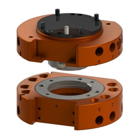
Manual, Robotic Tool Changer, QC-5 through QC-27 Document #9610-20-2254-09 2. Product Overview The Tool Changer provides flexibility to robot applications by allowing the robot to change customer tooling (e.g., grippers, vacuum cup tooling, pneumatic and electric motors, weld guns, etc.) automatically. The Tool Changer consists of a Master plate and a Tool plate. - Page 10 Manual, Robotic Tool Changer, QC-5 through QC-27 Document #9610-20-2254-09 Table 2.1—QC Tool Changer Models and Features Model Payload Flats Plate Pneumatic Ports Part No. (8) 1/8 NPT Pass 2,5,6 through ports 9120-021M-000-000-SQx-yyyy Master (2) M5 X 0.8 Lock/Unlock 9120-021M-000-000-SQx-yyyy-B 3,5,6...
-
Page 11: Master Plate Assembly
Manual, Robotic Tool Changer, QC-5 through QC-27 Document #9610-20-2254-09 2.1 Master Plate Assembly The Master plate assembly includes an anodized aluminum body, a hardened stainless-steel locking mechanism, and hardened steel alignment pins. The locking mechanism consists of a cam, a male coupling, and chrome-steel ball bearings. -
Page 12: Master Plate/Tool Plate Locking Mechanism
Manual, Robotic Tool Changer, QC-5 through QC-27 Document #9610-20-2254-09 2.3 Master Plate/Tool Plate Locking Mechanism The coupling of the Master plate and the Tool plate is achieved through a patented, high-strength, and stainless steel mechanism. During locking, steel balls in the Master plate are driven outward by a circular cam attached to a pneumatically actuated piston. -
Page 13: Optional Modules
Manual, Robotic Tool Changer, QC-5 through QC-27 Document #9610-20-2254-09 2.5 Optional Modules Tool Changers have (1) or (2) flats depending on the model. Optional modules support the pass-through of various utilities, such as signal, fluid/air, and power, etc. Refer to Table 2.2... - Page 14 Fastener Size, Property Recommended Thread Mounting Conditions Class, and type Torque Locker QC-5 and QC-11 Master plate to Robot Interface Plate or Sensor M3-30 10 in-lbs Interface plate, Supplied Fasteners (M3 socket head cap screws) Class 12.9 (1.13 Nm) M4-30 Class 12.9...
-
Page 15: Robot Interface Plates
Manual, Robotic Tool Changer, QC-5 through QC-27 Document #9610-20-2254-09 3.1 Robot Interface Plates The Master plate is typically attached to the robot arm. An interface plate can adapt the Master plate to a specific robot arm. Alignment features (dowel holes and bosses) accurately position and bolt holes secure the Master plate to the robot arm or an interface plate. -
Page 16: Master Plate Installation
4. Remove the cover plate. • For the QC-5 or QC-11, remove the (2) M3 hex nuts securing the cover plate to the Master plate. • For a QC-20 and QC-21, remove the (2) M3 socket flat head screws using a 2 mm hex key that secure the cover plate to the Master plate. - Page 17 Table 3.1 proper fasteners and torque. • For the QC-5 or QC-11 secure the Master plate to the interface plate with the (4) M3 socket head screws using a 2.5 mm hex key. • For the QC-20 and QC-21 secure the Master plate to the interface plate with the (4) M4 socket flat head screws using a 2.5 mm hex key.
-
Page 18: Master Plate Removal
5. Disconnect the Lock and Unlock sensor cables. 6. Remove the Master plate from the interface plate. • For a QC-5 or QC-11, remove the (4) M3 socket head cap screws securing the Master plate to the interface plate. •... -
Page 19: Tool Interface Plate
Manual, Robotic Tool Changer, QC-5 through QC-27 Document #9610-20-2254-09 3.4 Tool Interface Plate The Tool plate is attached to the customer’s tooling. An interface plate can adapt the Tool plate to customer tooling. Alignment features (dowel holes and a recess) accurately position and bolt holes secure the Tool plate to customer tooling. -
Page 20: Tool Plate Installation
Manual, Robotic Tool Changer, QC-5 through QC-27 Document #9610-20-2254-09 3.5 Tool Plate Installation In most applications, the customer end-effector attaches to the Tool plate with a custom interface plate. Refer to Section 3.4—Tool Interface Plate for design considerations. Tools required: 5 mm, 4 mm, or 3 mm hex key, torque wrench Supplies required: Clean rag, Loctite 222 or 242 1. -
Page 21: Optional Module Installation
Tool Changer. The optional modules are typically installed on Tool Changers by ATI prior to shipment. The following steps outline field installation or removal. 3.7.1 QC-5 and QC-11 Simple Electrical Module Installation Tools required: 2.5 mm hex key, torque wrench Supplies required: Clean rag, Loctite 222 1. -
Page 22: And Qc-11 Master Electrical Module Installation
Manual, Robotic Tool Changer, QC-5 through QC-27 Document #9610-20-2254-09 3.7.3 QC-5 and QC-11 Master Electrical Module Installation Tools required: 2.5 mm and 2 mm hex key, torque wrench Supplies required: Clean rag, Loctite 222 1. Place the Tool in a secure location. -
Page 23: And Qc-11 Tool Electrical Module Installation
Manual, Robotic Tool Changer, QC-5 through QC-27 Document #9610-20-2254-09 3.7.5 QC-5 and QC-11 Tool Electrical Module Installation Tools required: 2.5 mm hex key, 3/16” wrench, torque wrench Supplies required: Clean rag, Loctite 222 (if fasteners do not have pre-applied adhesive) 1. -
Page 24: Qc-20, Qc-21, And Qc-27 Flat A Optional K Series Module Installation
Manual, Robotic Tool Changer, QC-5 through QC-27 Document #9610-20-2254-09 3.7.7 QC-20, QC-21, and QC-27 Flat A Optional K Series Module Installation Tools required: 2.5 mm hex key, torque wrench Supplies required: Clean rag, Loctite 222 1. Place the Tool in a secure location. -
Page 25: Flat B Optional Module Installation
Manual, Robotic Tool Changer, QC-5 through QC-27 Document #9610-20-2254-09 5. Remove the (2) M3 socket head cap screws securing the module to the Tool Changer using a 2.5 mm hex key. Note: For the module on the Master, the Master plate may have to be removed refer to Section 3.3—Master Plate... -
Page 26: Flat B Optional Module Removal
Manual, Robotic Tool Changer, QC-5 through QC-27 Document #9610-20-2254-09 3.7.10 QC-21 Flat B Optional Module Removal Tools required: 2.5 mm and 3 mm hex key 1. Place the Tool in a secure location. 2. Uncouple the Master and Tool plates. - Page 27 Manual, Robotic Tool Changer, QC-5 through QC-27 Document #9610-20-2254-09 NOTICE: The sensor plate assembly comes assembled with the lock and unlock sensor installed. Do not remove the sensors, the sensors have been position properly from the factory. The sensor plate assembly has the detection shaft O-ring installed and lubricated, make sure it is present as shown in Figure 3.10.
- Page 28 Manual, Robotic Tool Changer, QC-5 through QC-27 Document #9610-20-2254-09 10. Insert a 3 mm hex key into the cam of the Tool Changer plate locking mechanism to hold the piston. 11. Using a 2.5 mm hex key, tighten the M3 socket head cap screw to 12 in-lbs (1.36 Nm).
-
Page 29: And Qc-21 Sip Assembly Installation
Manual, Robotic Tool Changer, QC-5 through QC-27 Document #9610-20-2254-09 CAUTION: Do not apply Lock or Unlock air pressure to the Tool Changer prior to installing an interface plate. Applying air pressure can damage the cover plate, O-ring or may cause injury to personnel from flying debris. Always install an interface plate and have the Tool Changer mounted securely to the robot before applying air pressure. - Page 30 Manual, Robotic Tool Changer, QC-5 through QC-27 Document #9610-20-2254-09 5. If the Tool Changer has a cover plate, remove the (2) M3 socket flat head screws that secure the cover plate to the Tool Changer Master plate using a 2 mm hex key.
- Page 31 Manual, Robotic Tool Changer, QC-5 through QC-27 Document #9610-20-2254-09 8. Press the detection shaft into the sensor plate assembly; push the shaft all the way through until it stops. 9. If the M3 socket head cap screw with O-ring does not have pre applied adhesive, apply Loctite primer 7649 to the threads of the M3 socket head cap screw and the internal threads of the piston.
- Page 32 Manual, Robotic Tool Changer, QC-5 through QC-27 Document #9610-20-2254-09 16. Look straight into the sensor plate assembly and verify the detection shaft does not touch the Lock and Unlock sensors. If the sensors touch the shaft, adjust the sensor position. Refer to Section 6.2.2—QC-20 and QC-21 Proximity Sensor Adjustment, Test, or Replacement.
-
Page 33: Lock And Unlock Pneumatic And Valve Requirements
Connect the lock and unlock air supplies to a single, 2-position, 4-way or 5-way valve with either a 4-port or 5-port configuration. Figure 3.19—QC-5 and QC-11 Lock and Unlock Pneumatic Connections 4 or 5 -way Valve Lock Port... -
Page 34: Electrical Connections
Manual, Robotic Tool Changer, QC-5 through QC-27 Document #9610-20-2254-09 Figure 3.20—QC-20 and QC-21 Lock and Unlock Pneumatic Connections 4 or 5 -way Valve Supply Clean, Dry, Lock Port Non -lubricated Air Unlock Port 60 – 100 psi (4.1 – 6.9 Bar) -
Page 35: Npn Type Lock And Unlock Sensors
Manual, Robotic Tool Changer, QC-5 through QC-27 Document #9610-20-2254-09 3.10.2 NPN Type Lock and Unlock Sensors The NPN Lock and Unlock sensors are 4 mm cylindrical inductive proximity sensor. Table 3.3—NPN (Current Sinking) Description Value Voltage Supply Range 10-30 VDC Output Current <... -
Page 36: Operation
Manual, Robotic Tool Changer, QC-5 through QC-27 Document #9610-20-2254-09 4. Operation The Master locking mechanism is pneumatically driven to couple and uncouple with the bearing race on the Tool plate. The Master plate utilizes air ports to provide lock and unlock pressure to the locking mechanism. -
Page 37: Coupling Sequence
Manual, Robotic Tool Changer, QC-5 through QC-27 Document #9610-20-2254-09 4.1 Coupling Sequence CAUTION: The locking mechanism must be in the unlock position when attempting to couple the Tool Changer. Failure to adhere to this condition may result in damage to the unit and/or the robot. -
Page 38: Uncoupling Sequence
Manual, Robotic Tool Changer, QC-5 through QC-27 Document #9610-20-2254-09 4.3 Uncoupling Sequence 1. Position the Tool plate in the tool stand such that there is little or no contact force between the Tool plate and tool stand. 2. Release air on the Lock port and apply air to the Unlock Port (if equipped, the Unlock sensor will indicate the Tool Changer is in the Unlocked position). -
Page 39: Tool Storage Considerations
Manual, Robotic Tool Changer, QC-5 through QC-27 Document #9610-20-2254-09 4.5 Tool Storage Considerations NOTICE: Tool stand design is critical to operation of the Tool Changer. Improperly designed tool stands can cause jamming and excessive wear of the Tool Changer components. -
Page 40: Maintenance
Manual, Robotic Tool Changer, QC-5 through QC-27 Document #9610-20-2254-09 5. Maintenance WARNING: Do not perform maintenance or repair on Tool Changer or modules unless the Tool is safely supported or placed in the tool stand, all energized circuits (e.g. electrical, air, water, etc.) are turned off, pressurized connections purged and power discharged from... -
Page 41: Preventive Maintenance
Manual, Robotic Tool Changer, QC-5 through QC-27 Document #9610-20-2254-09 5.1 Preventive Maintenance The Tool Changer and optional modules provide a long life with regular maintenance. A maintenance schedule for an application and a maintenance checklist is provided in the following table. Detailed assembly drawings are provided in Section 9—Drawings... -
Page 42: Cleaning And Lubrication Of The Locking Mechanism And Alignment Pins
Manual, Robotic Tool Changer, QC-5 through QC-27 Document #9610-20-2254-09 5.2 Cleaning and Lubrication of the Locking Mechanism and Alignment Pins 1. Place the Tool in a secure location. 2. Uncouple the Master and Tool plates. 3. Turn off and de-energize all energized circuits (e.g. electrical, air, water, etc.). - Page 43 Manual, Robotic Tool Changer, QC-5 through QC-27 Document #9610-20-2254-09 6. Check each ball bearing to make sure it moves freely in the male coupling. Additional cleaning may be necessary to free up any ball bearings that are sticking in place.
-
Page 44: Optional Electrical Module Pin Block Inspection And Cleaning
Manual, Robotic Tool Changer, QC-5 through QC-27 Document #9610-20-2254-09 5.3 Optional Electrical Module Pin Block Inspection and Cleaning Tools required: Nylon Brush (ATI Part Number 3690-0000064-60) 1. Place the Tool in a secure location. 2. Uncouple the Master and Tool plates. -
Page 45: Troubleshooting And Service Procedures
Manual, Robotic Tool Changer, QC-5 through QC-27 Document #9610-20-2254-09 6. Troubleshooting and Service Procedures The following section provides troubleshooting information to help diagnose conditions with the Tool Changer and service procedures to help resolve these conditions. WARNING: Do not perform maintenance or repair on Tool Changer or modules unless the Tool is safely supported or placed in the tool stand, all energized circuits (e.g. -
Page 46: Service Procedures
Manual, Robotic Tool Changer, QC-5 through QC-27 Document #9610-20-2254-09 6.2 Service Procedures The following service procedures provide instructions for inspection, adjustment, test, or replacement of components. 6.2.1 QC-11 and QC-27 Proximity Sensor Adjustment, Test, or Replacement The proximity sensors are extremely reliable and should not require frequent replacement. Should malfunctions occur, evaluate all other possible solutions before testing or replacing the sensor . - Page 47 Manual, Robotic Tool Changer, QC-5 through QC-27 Document #9610-20-2254-09 8. Thread the new proximity sensor into the Master plate assembly until it touches the detection shaft, then back the sensor out by a 1/2 turn. Figure 6.3—QC-11 and QC-27 Replace Proximity Sensor...
- Page 48 Manual, Robotic Tool Changer, QC-5 through QC-27 Document #9610-20-2254-09 CAUTION: Be careful not to over tighten set screw. Over tightening set screw can cause damage to the proximity sensor. Tighten until the nylon tip engages with the sensor threads and tighten 1/4 turn more.
-
Page 49: And Qc-21 Proximity Sensor Adjustment, Test, Or Replacement
Manual, Robotic Tool Changer, QC-5 through QC-27 Document #9610-20-2254-09 6.2.2 QC-20 and QC-21 Proximity Sensor Adjustment, Test, or Replacement The proximity sensors are extremely reliable and should not require frequent replacement. Should malfunctions occur, evaluate all other possible solutions before testing or replacing the sensor . - Page 50 Manual, Robotic Tool Changer, QC-5 through QC-27 Document #9610-20-2254-09 Figure 6.5—QC-20 and QC-21 Replace Proximity Sensor Sensor Interface Plate (SIP) Detection Shaft Hex Nut Proximity Sensor QC-21 Master Plate (Shown) (4) M4 Socket Flat Head Cap Screws 8. On the new sensor, back the sensor hex nut to the cable end of the sensor.
- Page 51 Manual, Robotic Tool Changer, QC-5 through QC-27 Document #9610-20-2254-09 10. From a top-down view of the sensor plate assembly, verify the detection shaft does not touch the Lock and Unlock sensors. If the sensors touch the shaft, adjust the sensor position.
-
Page 52: Rubber Bushing Inspection And Replacement
8. Safely resume normal operation. Figure 6.7 —QC-5, QC-11, QC-20, QC-21, and QC-27 Rubber Bushing Replacement (QC-21 Shown) Rubber Bushing Pinnacle Park • 1041 Goodworth Drive • Apex, NC 27539 USA • Tel: 919.772.0115 • Fax: 919.772.8259 •... -
Page 53: Qc-27M Alignment Pin Replacement
Manual, Robotic Tool Changer, QC-5 through QC-27 Document #9610-20-2254-09 6.2.4 QC-27M Alignment Pin Replacement Excessive alignment pin/bushing wear could indicate poor robot positioning during pickup/drop- off. Adjust the robot position as needed. Check the tool stand for wear and alignment problems. If necessary, replace the alignment pins. -
Page 54: Optional Electrical Module V-Ring Seal Inspection And Replacement
Manual, Robotic Tool Changer, QC-5 through QC-27 Document #9610-20-2254-09 6.2.5 Optional Electrical Module V-ring Seal Inspection and Replacement The seal protects the electrical connection between the Master and Tool module. If the seal becomes worn or damaged it needs to be replaced. -
Page 55: Specifications
Manual, Robotic Tool Changer, QC-5 through QC-27 Document #9610-20-2254-09 7. Specifications Table 7.1—Tool Changer Specifications Tool Changer Model Specification QC-5 QC-11 QC-20 QC-21 QC-27 Recommended Max 18 lbs. 35 lbs. 55 lbs. 55 lbs. 85 lbs. Payload (8.2 kg) (16 kg) (25 kg) -
Page 56: Serviceable Parts
Manual, Robotic Tool Changer, QC-5 through QC-27 Document #9610-20-2254-09 8. Serviceable Parts The following items are commonly used as spare parts for the QC-5 through QC-27 Tool Changers. 8.1 Models QC-5 Serviceable Parts QC-5 Master plate Item No. Part Number... -
Page 57: Models Qc-11 Serviceable Parts
Manual, Robotic Tool Changer, QC-5 through QC-27 Document #9610-20-2254-09 8.2 Models QC-11 Serviceable Parts QC-11 Master plate Item No. Part Number Description QC-11 Master Assembly, No Options (Orange Anodized) 9120-011M-000-000 9120-011M-000-000-B QC-11 Master Assembly, No Options (Black Anodized) 4010-0000009-02 M5 Rubber Bushing, Nitrile, Light-5... -
Page 58: Models Qc-20 Pm5 Model Serviceable Parts
Manual, Robotic Tool Changer, QC-5 through QC-27 Document #9610-20-2254-09 8.3 Models QC-20 PM5 Model Serviceable Parts QC-20 Master plate Item No. Part Number Description 9120-020M-000-PM5 QC-20 Master, 12 air ports, no options (Orange Anodized) QC-20 Master, 12 air ports, no options (Black Anodized) -
Page 59: Models Qc-20 With 16 M5 X 0.8 Pass Through Ports Serviceable Parts
Manual, Robotic Tool Changer, QC-5 through QC-27 Document #9610-20-2254-09 8.4 Models QC-20 with 16 M5 X 0.8 Pass through Ports Serviceable Parts QC-20 Master plate Item No. Part Number Description 9120-020M-000-P16 QC-20 Master, 16 Ports, No Options, (Orange Anodized) 9120-020M-000-P16-B... -
Page 60: Models Qc-21 Serviceable Parts
Manual, Robotic Tool Changer, QC-5 through QC-27 Document #9610-20-2254-09 8.5 Models QC-21 Serviceable Parts QC-21 Master plate Item No. Part Number Description 9120-021M-000-000 QC-21 Master, no options, 1/8 NPT ports (Orange Anodized) 9120-021M-000-000-B QC-21 Master, no options, (Black Anodized) 1/8 NPT ports... -
Page 61: Models Qc-27 Serviceable Parts
Manual, Robotic Tool Changer, QC-5 through QC-27 Document #9610-20-2254-09 8.6 Models QC-27 Serviceable Parts QC-27 Master plate Item No. Part Number Description 9120-027M-000-000 QC-27 Master, no options, 1/8 NPT ports (Orange Anodized) 9120-021M-000-000-E QC-27 Euro Master, no options, G 1/8 (BSPP) (Black Anodized) -
Page 62: Drawings
Manual, Robotic Tool Changer, QC-5 through QC-27 Document #9610-20-2254-09 9. Drawings 9.1 QC-5 Tool Changer with EA2 Module Pinnacle Park • 1041 Goodworth Drive • Apex, NC 27539 USA • Tel: 919.772.0115 • Fax: 919.772.8259 • www.ati-ia.com... -
Page 63: Tool Changer With A15 Module
Manual, Robotic Tool Changer, QC-5 through QC-27 Document #9610-20-2254-09 9.2 QC-11 Tool Changer with A15 Module Pinnacle Park • 1041 Goodworth Drive • Apex, NC 27539 USA • Tel: 919.772.0115 • Fax: 919.772.8259 • www.ati-ia.com... -
Page 64: Tool Changer With K19 Module
Manual, Robotic Tool Changer, QC-5 through QC-27 Document #9610-20-2254-09 9.3 QC-20 Tool Changer with K19 Module Pinnacle Park • 1041 Goodworth Drive • Apex, NC 27539 USA • Tel: 919.772.0115 • Fax: 919.772.8259 • www.ati-ia.com... -
Page 65: Tool Changer With K19 Module
Manual, Robotic Tool Changer, QC-5 through QC-27 Document #9610-20-2254-09 9.4 QC-21 Tool Changer with K19 Module Pinnacle Park • 1041 Goodworth Drive • Apex, NC 27539 USA • Tel: 919.772.0115 • Fax: 919.772.8259 • www.ati-ia.com... -
Page 66: Euro Tool Changer
Manual, Robotic Tool Changer, QC-5 through QC-27 Document #9610-20-2254-09 9.5 QC-21 Euro Tool Changer Pinnacle Park • 1041 Goodworth Drive • Apex, NC 27539 USA • Tel: 919.772.0115 • Fax: 919.772.8259 • www.ati-ia.com... - Page 67 Manual, Robotic Tool Changer, QC-5 through QC-27 Document #9610-20-2254-09 Pinnacle Park • 1041 Goodworth Drive • Apex, NC 27539 USA • Tel: 919.772.0115 • Fax: 919.772.8259 • www.ati-ia.com...
- Page 68 Manual, Robotic Tool Changer, QC-5 through QC-27 Document #9610-20-2254-09 Pinnacle Park • 1041 Goodworth Drive • Apex, NC 27539 USA • Tel: 919.772.0115 • Fax: 919.772.8259 • www.ati-ia.com...
-
Page 69: Tool Changer
Manual, Robotic Tool Changer, QC-5 through QC-27 Document #9610-20-2254-09 9.6 QC-27 Tool Changer Pinnacle Park • 1041 Goodworth Drive • Apex, NC 27539 USA • Tel: 919.772.0115 • Fax: 919.772.8259 • www.ati-ia.com... - Page 70 Manual, Robotic Tool Changer, QC-5 through QC-27 Document #9610-20-2254-09 Pinnacle Park • 1041 Goodworth Drive • Apex, NC 27539 USA • Tel: 919.772.0115 • Fax: 919.772.8259 • www.ati-ia.com...
- Page 71 Manual, Robotic Tool Changer, QC-5 through QC-27 Document #9610-20-2254-09 Pinnacle Park • 1041 Goodworth Drive • Apex, NC 27539 USA • Tel: 919.772.0115 • Fax: 919.772.8259 • www.ati-ia.com...
-
Page 72: Terms And Conditions Of Sale
Manual, Robotic Tool Changer, QC-5 through QC-27 Document #9610-20-2254-09 10. Terms and Conditions of Sale The following Terms and Conditions are a supplement to and include a portion of ATI’s Standard Terms and Conditions, which are on file at ATI and available upon request.
Need help?
Do you have a question about the QC-5 and is the answer not in the manual?
Questions and answers