Advertisement
Quick Links
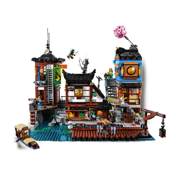
Light My Bricks: LEGO Ninjago City Docks
70657 Lighting Kit
The following page is the instructions for the Light My Bricks LEGO Ninjago
City Docks (70657) LED light kit.
To ensure a trouble-free installation of your light kit, please read and
follow each step carefully.
If you run into any issues, please refer to the online troubleshooting guide.
Please note: This page lists instructions for the
LED light kit only.
Package Contents:
8x White Strip Lights
•
1x Blue Strip Light
•
10x White 15cm Bit Lights
•
2x Orange 30cm Bit Lights
•
4x 6-Port Expansion Boards
•
1x 8-Port Expansion Board
•
1x Flicker E ects Board
•
5x 5cm Connecting Cables
•
. . .
Advertisement

Related Manuals for LIGHT MY BRICKS 70657


Summary of Contents for LIGHT MY BRICKS 70657
- Page 1 Light My Bricks: LEGO Ninjago City Docks 70657 Lighting Kit The following page is the instructions for the Light My Bricks LEGO Ninjago City Docks (70657) LED light kit. To ensure a trouble-free installation of your light kit, please read and follow each step carefully.
- Page 2 6x 15cm Connecting Cables • 3x 30cm Connecting Cables • 1x AA Battery Pack (requires 3x AA Batteries) • 12x Adhesive Squares LEGO Pieces: • 5x Plate 1x6 (any colour) • . . . Laying cables in between and underneath bricks Cables can t in between and underneath LEGO®...
- Page 3 Take extra care when inserting connectors to ports of Expansion Boards. Connectors can be inserted only one way. With the expansion board facing up, look for the soldered “=” symbol on the left side of the port. The connector side with the wires exposed should be facing toward the soldered “=”...
- Page 4 Installing Bit Lights under LEGO® bricks and plates. When installing Bit Lights under LEGO® pieces, ensure they are placed the correct way up (Yellow LED component exposed). You can either place them directly on top of LEGO® studs or in between. .
- Page 5 . . . 1.) We will start by installing lights to the left side of the building. Firstremove all levels as well as the boat from the set. Take the second oor and place it on its back so we can access underneath.
- Page 6 2.) Take the Blue Strip Light and using it’s adhesive backing, stick it to the base of a provided LEGO Plate 1x6 Take a 5cm Connecting Cable and connect it to the strip light. Connect the other end of the cable to the end port of a 6-Port Expansion Board Stick 2x Adhesive Squares to the base of the expansion board and then mount both expansion board and strip light underneath the second oor in the below position.
- Page 7 3.) Take a 15cm Connecting Cable and connect it to the left port on the Blue Strip Light. Lay the cable underneath the 2x8 Plate in between studs as per below.
- Page 8 Take the AA Battery Pack and insert 3x AA batteries to it. Connect the Battery Pack cable to the 6-port expansion board as per below.
- Page 9 4.) Take another 15cm Connecting Cable and connect it to one of the ports on the 6-port Expansion Board. Lay the cable underneath the right 2x8 plate ensuring it is laid in between studs.
- Page 10 Turn the oor over and then reconnect it back on top of the ground oor ensuring the 15cm Connecting Cable from each side is sticking out.
- Page 11 The AA Battery Pack can be positioned against the wall as per below. Turn it on the test the Blue Strip Light is working OK.
- Page 12 5.) Take the other end of the 15cm cable from the left side and thenpull it up and then secure it underneath the 1x8 tile on the top of the oor. 6.) Take the third oor and remove the lantern piece from the behind and then turn the whole oor onto it’s left at side so that we can access underneath.
- Page 13 7.) Remove the pieces from the top of the lantern.
- Page 14 Take a White 15cm Bit Light and place it inside the hole of the lantern piece. Secure it in place by reconnecting the pieces we removed earlier ensuring the LED component is facing the front of the lantern and that the cable is facing the back.
- Page 16 Connect the other end of the Bit Light cable from the lantern to a new 6- Port Expansion Board. 8.) Take 2x White Strip Lights and stick them to 2x Provided LEGO Plates 1x6.
- Page 17 Connect them together using a 5cm Connecting Cable then take another 5cm Connecting Cable and connect it to the outside port of one of the strip lights. Connect the other end of the 5cm connecting cable to the 6 port expansion board and then take a 30cm Connecting Cable and connect it to left port on the other Strip Light.
- Page 18 9.) Disconnect the brown 1x6 plate on the right side underneath thethird ood, then mount both strip lights underneath in the below position ensuring the 30cm Connecting cable is facing the bottom. Reconnect the brown 1x6 plate we removed earlier and then lay the 30cm connecting cable underneath the bottom brown 1x6 plate.
- Page 19 Ensure all cables are laid in between studs 10.) Take the other end of the 30cm Connecting Cable and thread it down the following space in the corner. Pull it all the way out from underneath.
- Page 20 Eliminate excess cable from the lantern bit light by folding and then twisting the cable around itself a few times. 11.) Turn the third oor over and remove the following tiles from the top to allow us to remove the door section.
- Page 21 Pull the cable up inside the room and then with the cable in the corner, reconnect the door ensuring the cable is pulled up in between the door and red bricks before reconnecting the tiles over the top.
- Page 22 12.) Take the third oor and place it over the second oor. Take the15cm connecting cable from the left side underneath the brown tile and connect it to the 6-port expansion board below.
- Page 23 Tuck the expansion board and cables inside the space underneath as per below before securing the third oor on top of the second oor. Turn the battery pack ON to test all lights are working OK.
- Page 24 13.) We will now light up the lanterns on the third oor. First disconnect the square tiles and pieces from the two left corners to allow us to remove the lantern sections.
- Page 25 Disconnect the gold pieces from underneath each lantern. 14.) Take a White 15cm Bit Light and with the LED facing the front of the lantern, place it up inside the hole of the lantern piece. Press the cable up along the back side of the lantern before reconnecting the gold piece underneath.
- Page 26 Repeat this process to install another White 15cm Bit Light to the other lantern...
- Page 27 15.) Reconnect each lantern to the top corners of the third oor. Ensure the cables are laid in between bricks and studs before reconnecting the square tiles and pieces over the top.
- Page 28 Take a new 6-port Expansion Board and connect the two lantern bit light cables as well as the 30cm connecting cable (from underneath) to it. Test the two lanterns are working OK. 16.) Take 2x Adhesive Squares and stick them underneath the 6-port Expansion Board.
- Page 29 Hide excess cables and prevent them from hanging down and visibile from the window by laying them underneath the tiles on the top of the oor as per below.
- Page 30 17.) Take the roof of the left building and turn it over onto it’s back so we can access underneath. Disconnect the following black 1x6 plate from underneath.
- Page 31 Take a White Strip Light and stick it to the base of the black 1x6 plate we just removed. Take a 5cm Connecting Cable and connect it to one end of the strip light. Mount the strip light underneath the roof in the following position ensuring the cable is facing up.
- Page 32 18.) Take the roof above the third oor and connect the other end of the 5cm connecting cable to a spare port on the 6-port expansion board underneath before securely reconnecting the roof.
- Page 33 Test all lights in the left building are working OK. 19.) We will now light up the middle building. Start by removing all upper sections and then follow the images below to remove sections from the top of the fruit market.
- Page 35 20.) Take a White Strip Light and connect a 15cm Connecting Cable to the right port.
- Page 36 Take the other end of the 15cm connecting cable from the left building and connect it to the left port on the strip light. Stick the strip light underneath the fruit market roof in the below position. 22.) Remove the following pieces from the steps in between left and middle buildings.
- Page 37 Reconnect the fruit market roof ensuring cables are facing inside. Lay the cable from the left building underneath the black and tan pieces on the right of the steps.
- Page 38 Reconnect pieces from the steps ensuring the cable is laid underneath in between studs. Reconnect the pieces on top of the fruit market.
- Page 39 23.) Turn the set around to the back and then take a 6-port Expansion Board and connect the 15cm connecting cable from the fruit market roof strip light to it. Remove the following pieces from chicken area.
- Page 41 Turn the set around and use the LEGO removal tool to remove more pieces from the front of the chicken area.
- Page 42 24.) Take 2x Orange 30cm Bit Lights and then stick them to the back of the chicken sign in the below position using 2x Adhesive Squares...
- Page 43 Reconnect the chicken sign to the front ensuring the cables are rst threaded inside then reconnect the rst dark grey tile over the top. Turn the set around to the back and lay the cables toward the back and then to the right before reconnecting the remaining pieces over the top.
- Page 44 Pull both cables up and secure them underneath the dark grey curved tile on the top as per below.
- Page 45 25.) Take the Flicker E ects Board and connect the two Orange Bit Light cables to the OUT ports. Take a 5cm Connecting Cable and connect it to the IN port and then connect the other end to the 6-port expansion board underneath. Turn the battery pack ON to test the orange lights and icker e ect is working OK in the chicken area.
- Page 46 26.) Take a 30cm Connecting Cable and connect it to the 6-port expansion board, then using 3x Adhesive Squares, mount the expansion board and icker e ects board to the inside of the fruit market in the below position...
- Page 47 Tidy up cables by laying the excess orange bit light cables underneath the dark grey curved tiles and brown tiles along the top. Pull the 30cm Connecting Cable to the left and lay it in between studs in the top corner before reconnecting the the black plate and left roof section.
- Page 48 27.) Take the upper middle section and disconnect the two lanterns.
- Page 49 Follow the same process used in step 7 to install 2x White 15cm Bit Lights to the two lanterns.
- Page 50 28.) Reconnect the lanterns to the upper level then disconnect the roof and place it on it’s back so we can access underneath.
- Page 51 29.) Take a White Strip Light and stick it to a provided LEGO Plate 1x6. Take a 30cm Connecting Cable and connect one end to the Strip Light. Mount the Strip Light underneath the roof in the below position ensuring the cable is facing the left side as per below.
- Page 52 Secure the cable underneath the brown 1x2 plate Reconnect the roof to the upper level then bring the cable down in between the left angled roof.
- Page 53 Pull the cable down and lay it underneath the long vertical brown tile as per below. 30.) Disconnect the 2x14 brown plate from bottom of the upper level then lay all cables underneath toward the inside in between studs before reconnecting the 2x14 plate.
- Page 54 Bring the entire upper level over the fruit market and connect all three cables to the 6-port expansion board underneath.
- Page 55 Secure the upper level on top of the fruit market and test that all lights installed so far are working OK...
- Page 56 31.) Turn the set back around to the front then take the second level from the right building and turn it onto it’s back so we can access underneath.
- Page 57 32.) Take another White Strip Light and stick it to a provided LEGO Plate 1x6. Take a 15cm Connecting Cable and connect it to the strip light’s right port. Mount the strip light underneath the second level in the following position ensuring the cable is facing the right.
- Page 58 Turn the second level over and pull the 15cm cable up the right side. Secure it underneath the brown tile on the top. 33.) We will now install lights to the lanterns outside the entrance. First disconnect the following pieces on the top to allow us to remove the two lantern sections...
- Page 59 34.) Follow the process used in step 14 to install another 2x White 15cm Bit Lights to the lantern pieces...
- Page 61 Reconnect the two lantern pieces back to the front of the second level then reconnect pieces along the top ensuring cables are laid in between bricks and studs.
- Page 62 35.) We will now install lights to the lamps inside the room. Firstdisconnect the tiles in each top corner to allow us to disconnect the lamp sections. Disconnect the trans orange round plates from each lamp then take a White 15cm Bit Light and place it directly over one of the lamps. Secure the bit light in place by reconnecting the trans orange round plates from one side over the top.
- Page 63 Repeat this process to install another White 15cm Bit Light to the other lamp. Reconnect the lamps to the inside of the room and then reconnect the brown tiles over the top ensuring the cables are laid the same way as shown below...
- Page 64 36.) Take an 8-Port Expansion Board and connect all four bit light cables as well as 15cm cable from underneath to it Take a new 15cm Connecting Cable and connect it to a spare port on the expansion board then stick 2x Adhesive Squares to the back.
- Page 65 Remove the right sword from the right wall and then mount the expansion board to the inside of the room along the top as shown below.
- Page 66 37.) Pull the 15cm cable out toward the right of the building and then secure it underneath the following brown tile. Neaten up cables and prevent them from hanging down and visible by hiding them underneath the tiles along the top as shown below.
- Page 67 38.) Bring the entire second level above the ground level then take theother end of the 30cm cable from the fruit market and lay it underneath the following tile.
- Page 68 Connect the cable to the strip light underneath the second level before securing he second level on top. Test all lights are working OK but turning the battery pack ON.
- Page 69 39.) Take the third level from the right building and disconnect the roof as well as lantern from the back. Follow the same process used in step 7 to install a White 15cm Bit Light to the lantern.
- Page 70 Reconnect the lantern then disconnect the light grey 2x12 plate from the bottom of the oor and lay the lantern cable underneath it ensuring it is in between studs before reconnecting the 2x12 plate.
- Page 71 40.) Bring the entire third level over the second level and connect the lantern bit light cable to a spare port on the 8-port expansion board underneath before securing the third level on top.
- Page 72 41.) Take a 2x White Strip Lights and connect them together using the remaining 15cm Connecting Cable.
- Page 73 Take one of the Strip Lights and stick it directly to the roof of the third oor ensuring the cable is facing the left as shown below. This will be used to shine up on to the pink roof feature. Pull the cable down the side and secure itunderneath the black round tile with hole.
- Page 74 Bring the cable down and lay it underneath the 1x8 tile as shown below Disconnect the two trans bright green bars as well as the four dark grey clips from the ceiling.
- Page 75 Stick the second strip light to the dark grey tile in the following position. Connect the trans bright green bars with clips to new positions as per below, so that the trans bright green bars are directly over the top of the strip light LEDs.
- Page 76 Hide the connecting cable underneath the cream coloured ‘L’ piece. 43.) Place the roof over the third level and then locate the loose 15cmconnecting cable from the right side of the building and connect it to the Strip Light on the roof ceiling.
- Page 77 Before securing the roof, secure the cable underneath the blue tile on top of the third oor.
- Page 78 . . . This nally completes installation of the Ninjago City Docks 70657 Light Kit..
Need help?
Do you have a question about the 70657 and is the answer not in the manual?
Questions and answers