Advertisement
Quick Links
Advertisement

Related Manuals for LIGHT MY BRICKS LEGO Star Wars Darth Vader Castle 75251 Lighting Kit


Summary of Contents for LIGHT MY BRICKS LEGO Star Wars Darth Vader Castle 75251 Lighting Kit
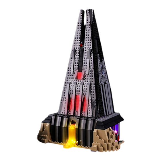
- Page 1 Light My Bricks: LEGO Star Wars Darth Vader Castle 75251 Lighting Kit...
- Page 3 Cables can fit in between and underneath LEGO® bricks, plates, and tiles providing they are laid correctly between the LEGO® studs. Do NOT forcefully join LEGO® together around cables; instead ensure they are laying comfortably in between each stud. CAUTION: Forcing LEGO® to connect over a cable can result in damaging the cable and light. Connecting cable connectors to Expansion Boards Take extra care when inserting connectors to ports of Expansion Boards.
- Page 4 Incorrectly inserting the connector can can result in bent pins inside the port or possible overheating of the expansion board when connected. Connecting cable connectors to Strip Lights Take extra care when inserting connectors to ports on the Strip Lights. Connectors can be inserted only one way.
- Page 5 OK, Let’s Begin! 1.) We will start by first installing lights to the lava at the front of the castle. Firstdisconnect the following black tiles at the front, then turn the castle around and remove the tie fighter. Gently press up against the following sections to lift up the entire top half of the castle.
- Page 7 Turn the base of the castle back around to the front and remove following sections:...
- Page 9 2.) Take the following section and disconnect all the trans coloured pieces, thentake 2x White 15cm Bit Lights and with the cables facing up, place the bit lights down in the following positions, in between studs. Secure the lights in place by reconnecting the trans coloured section over the top.
- Page 10 3.) Take both cables and thread them through the space on the right, whichleads to the inside of the castle. Pull the cables all the way out from the inside, then reconnect the lava section. Ensure both cables are neatly laid along the right of the following light grey stud.
- Page 11 4.) Take another White 15cm Bit Light and with the other end of the cable facing the right, place the bit light in between the two grey studs. Ensuring the cable is laid toward the right around the side closest to the front, secure the bit light in place by reconnecting the trans orange wall piece over the top.
- Page 12 Reconnect the two dark grey wall sections starting with the one on the right. Ensure the three cables are laid around the far left stud before reconnecting the left wall section over the top.
- Page 13 5.) Take your AA Battery Pack and insert 3x AA Batteries to it. Connect the battery pack cable to a 6-Port Expansion Board, then connect the three bit light cables to it. Turn the battery pack ON to test that all three lights are working OK. Note: If you experience any issues with the lights not working and suspect an issue with a component, please try a different port on the expansion board to verify where the fault lies (with the light or expansion board).
- Page 14 6.) Take the following section we removed earlier and disconnect the light greyplate from underneath. Disconnect the trans orange section, then reconnect the light grey plate to the front of the castle. Take 2x White 15cm Bit Lights and with the cables facing the back, place them over the two trans orange round tiles.
- Page 15 Reconnect the section we removed the light grey plate from earlier, ensuring the cables are first laid in between studs. Continue to reconnect surrounding sections we removed in step 1.
- Page 16 7.) From the inside of the castle, connect the two bit light cables we justinstalled to the next ports along the 6-port expansion board, then turn ON the battery Pack to test all the lava lights are working OK.
- Page 17 Note: If you experience any issues with the lights not working and suspect an issue with a component, please try a different port on the expansion board to verify where the fault lies (with the light or expansion board). To correct any issues with expansion board ports, please view the section addressing expansion board issues on our online troubleshooting guide.
- Page 18 To configure the effect used in the Light My Bricks example, set the switch to the far right for ‘pulse’ effect. Turn the wheel all the way to left for the slowest speed.
- Page 19 Connect the other end of the 5cm cable to the IN port on the Multi Effects Board (where we disconnected the battery pack from). 9.) Thread your AA Battery Pack through the space on the left side of the castle.Pull the cable in from the inside and connect it to the second 6-port expansion board we installed.
- Page 20 Neaten up cabling from the inside of the castle by grouping all the cables from the lava section and twisting/folding them together to form a neat bunch.
- Page 21 10.) We will now install a light to the pink diamond on the outside of the castle. First disconnect the wall section it sits on then disconnect the trans pink piece. Take a Pink 30cm Bit Light and with the cable facing behind, place it over the red stud. Secure the Bit Light in place by reconnecting the trans pink piece over the top.
- Page 22 Turn this section around to the back, then fold the cable down the back of the section. Reconnect this section to the castle base, then thread the pink bit light cable through the same space we threaded the battery pack cable through. Pull it all the way out from the inside then connect it to the second 6-port expansion board we installed.
- Page 23 Note: If you experience any issues with the lights not working and suspect an issue with a component, please try a different port on the expansion board to verify where the fault lies (with the light or expansion board). To correct any issues with expansion board ports, please view the section addressing expansion board issues on our online troubleshooting guide.
- Page 24 Reconnect the control panel, then thread the other end of the cable through the following space. Pull it all the way out from the inside of the castle, then thread the cable in between the wall and control panel. Continue to thread it around the next wall section to lead back inside the castle.
- Page 25 Hide the cable by disconnecting the following section, then reconnecting it over the top of the cable as shown below.
- Page 26 Connect the flashing white bit light cable it to the next spare port on the 6-port expansion board, then turn ON the battery pack to test the light is working OK. Note: If you experience any issues with the lights not working and suspect an issue with a component, please try a different port on the expansion board to verify where the fault lies (with the light or expansion board).
- Page 27 Lift up the section so we can access underneath, then secure the flashing white 30cm bit light cable underneath the following 2×2 plate. Take a 15cm Connecting cable and connect one end to a spare port on the second 6-port Expansion Board.
- Page 28 13.) We will now install lights to the main section of the castle. First pull out the black technic pin on the right side, then disconnect the two walls by unclipping them from the bottom.
- Page 29 Remove the Darth Vader’s bacta tank, disconnect the top of it as shown below:...
- Page 30 14.) Take a Cool White 30cm Bit Light and with the led facing down and cable laid behind, place if over the top of the tank, then secure it in place by reconnecting the top section. If you look up from the front of the tank, you should be able to see the Bit Light facing down. Turn the tank around to the back and fold the cable down and secure it underneath the black angled brick at the bottom.
- Page 31 Reconnect the bacta tank then thread the cable behind and out the right side of this section. 15.) Remove the Darth Sidious hologram from the level above and disassembleit as shown below:...
- Page 32 Take another Cool White 30cm Bit Light and place it over the black base’s stud. Secure the bit light in place by connecting a provided Trans Light Blue Round Plate 1×1 over the top, then reconnect the hologram piece ensuring the cable is facing the back.
- Page 33 Reconnect this section back to the castle, then lay the cable behind Darth Vader’s throne and around to the right. 16.) Take both ends of the Cool White Bit Light cables and connect each to oneof the OUT ports on a Flicker effects Board Secure both cables underneath the following light grey plate with clip, then fold/twist the two cables around each other into a neat bunch as shown below:...
- Page 34 Test the flickering lights by connecting your AA Battery Pack to the IN port on the Flicker Effects Board. Turn the battery pack on to see the bacta tank and hologram come to life. Note: If you experience any issues with the lights not working and suspect an issue with a component, please try a different port on the expansion board to verify where the fault lies (with the light, expansion board or effects board).
- Page 35 17.) Disconnect the AA Battery Pack, then connect a 5cm Connecting Cable to the IN port on the flicker effects board. Connect the other end of the cable to a new 6-Port Expansion Board. 18.) Take 2x Red Strip Lights and using their adhesive backing, stick them to the bases of the provided 2x Black Plate 1×6, then connect the two strip lights together using a 5cm Connecting Cable.
- Page 36 Take a 30cm Connecting Cable and connect one end to the right strip light, then take a 15cm Connecting Cable and connect one end to the left strip light. 19.) Lift up the base where the darth vader meditation chamber is, then mountboth Red Strip Lights underneath it in the below positions.
- Page 37 Take the other end of the 30cm Connecting Cable and thread it up the following space, which leads to the floor above (darth vader chamber). Pull the cable all the way out.
- Page 38 Connect the other end of the 30cm cable to the 6-Port Expansion Board below, then connect your AA Battery Pack to another spare port on the expansion board. Turn ON the battery pack to test the red strip lights are working OK. Note: If you experience any issues with the lights not working and suspect an issue with a component, please try a different port on the expansion board to verify where the fault lies (with the light or expansion board).
- Page 39 Take another Red Strip Light and using it’s adhesive backing, stick it to the bast of another provided Black Plate 1×6. Take the other end of the 15cm Connecting Cable from the red strip light from previous step and connect it to the Red Strip light from this step.
- Page 40 Take another 2x Red Strip Lights and using their adhesive backings, stick them to the 21.) bases of another provided 2x Black Plate 1×6.
- Page 41 Take the other end of the 15cm Connecting Cable and thread it up to the top level and connect it to one of the Red Strip Lights. Take a new 30cm Connecting Cable and connect one end to the other side of the Red Strip Light. 22.) Mount the Red Strip Light to the inside of the left wall in the followingposition.
- Page 42 Bring the other end of the 30cm Connecting Cable underneath the top level to bring it around to the right side. Connect it to the other spare Red Strip Light from previous step.
- Page 43 23.) Before reconnecting the main right wall section, ensure the bit light cablesand connecting cable are laid to the left side of the light grey clip.
- Page 44 Mount the Red Strip Light from previous step to the inside of the right wall in the following position. Eliminate excess cable by looping the connecting cable underneath the black 1×6 plate. 24.) Take Darth Vader and disconnect his lightsaber and replace it with theprovided Red Light My Bricks Lightsaber.
- Page 45 Place Darth Vader in his chamber (or anywhere on this floor) and bring the lightsaber cable behind and thread it through space in between this floor and the right wall. Pull the cable down from the outside, then secure it underneath the right wall.
- Page 46 Securely reconnect the right wall section by pushing in the black technic pin on the right, then connect the lightsaber cable to the 6-port Expansion Board underneath.
- Page 47 Connect the AA Battery Pack to a spare port on the 6-port Expansion Board and turn it ON to test all the lights in this main section are working OK.
- Page 48 Note: If you experience any issues with the lights not working and suspect an issue with a component, please try a different port on the expansion board to verify where the fault lies (with the light, expansion board or effects board). To correct any issues with expansion board ports, please view the section addressing expansion board issues on our online troubleshooting guide.
- Page 49 Secure the cable in place by laying it underneath the tan coloured 1×1 angled tile. 26.) Carefully turn the main section of the castle onto it’s front so we can accessunderneath. Take 2x White Strip Lights and using their adhesive backings, stick them to the bases of provided 2x Black Plate 1×6.
- Page 50 Take a new 5cm Connecting Cable and connect it to the other end of one of the white strip lights. Connect the other end of the cable to the 6-port expansion board underneath this section. 27.) Mount both strip lights underneath the main section of the castle in thefollowing positions.
- Page 51 Take 4x Adhesive Squares and stick two to the back of the expansion board, and another two to the back of the flicker effects board. Mount both expansion board and effects board to the side of the underneath section as shown below:...
- Page 52 28.) Take the main section of the castle over the top of the base section. Locatethe other end of the 15cm Connecting Cable from step 12 and connect it to a spare port on the 6-port expansion board underneath the main section of the castle. Securely reconnect the main section on top of the base section ensuring you first connect the right side (to prevent pinching cables on the right side)
Need help?
Do you have a question about the LEGO Star Wars Darth Vader Castle 75251 Lighting Kit and is the answer not in the manual?
Questions and answers