Table of Contents
Advertisement
Quick Links
Advertisement
Table of Contents

Related Manuals for Pulsar UltraTWIN


Summary of Contents for Pulsar UltraTWIN
- Page 1 UltraTWIN (UL) Instruction Manual...
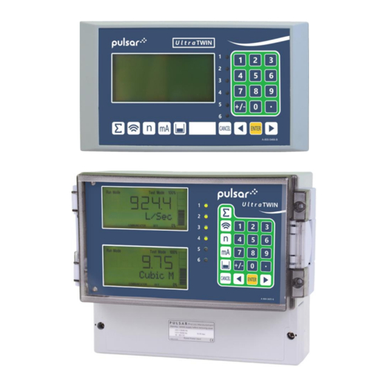
- Page 3 Pulsar Measurement operates a policy of constant development and improvement and reserves the right to amend technical details, as necessary. The UltraTWIN shown on the cover of this manual is used for illustrative purposes only and may not be representative of the actual UltraTWIN supplied.
-
Page 4: Table Of Contents
FM ............................27 Voltage selector and fuse location................29 Preparation for Operation ..................... 30 Maintenance ........................31 Chapter 3 How To Use Your UltraTWIN ............... 32 Operating the Controls ....................32 Run Mode ..........................34 Program Mode ........................34 Points of Measurement (P1 and P2) ................34 How to Access Program Mode .................. - Page 5 PULSAR MEASUREMENT Test Mode ..........................40 Using the Serial Interface ....................41 Parameter Defaults ......................43 Chapter 4 Quick Setup Guide ................... 44 Enter Program Mode ....................... 44 Choose Quick Setup ......................44 Level or Volume ......................... 45 Example 1 Level Monitoring with Alarms ..............51 Example 2 Level Monitoring and Control (up or down) ........
- Page 6 ULTRATWIN (UL) INSTRUCTION MANUAL Universal Calculations (P700=6) .................. 99 Chapter 5 Parameter Guide ..................... 100 Menu System ........................100 Top Level Menu ....................... 100 Application Menu ......................101 Relays Menu ........................102 Pump “Advanced” Menu ....................103 Digital Inputs Menu......................104 Data Logs Menu ......................
- Page 7 PULSAR MEASUREMENT Pump Run On ........................139 Starting ..........................139 Stopping ..........................140 Pump Exercising ......................140 Wall Cling ........................... 141 Digital Inputs ........................142 Digital Input Parameters ....................148 Digital Inputs ........................150 Digital Input ........................152 Data Log parameters ..................... 153 Totaliser Audits ........................
- Page 8 ULTRATWIN (UL) INSTRUCTION MANUAL mA Output 1 Parameters ..................... 181 Range ........................... 181 Operation ........................... 182 Setpoint ..........................182 mA1 Limits ......................... 183 mA1 Trim ..........................183 mA1 Failsafe ........................184 mA1 Allocation ......................... 184 mA Output2 Parameters ....................185 Range ...........................
- Page 9 PULSAR MEASUREMENT System Information ......................198 Date & Time ........................199 LED Colour ......................... 199 Watchdog ........................... 200 Daylight Saving Time ..................... 201 Device Comm........................205 RS232 Set Up ........................205 RS 485 Set Up ........................205 Remote Alarm ........................206 Test Parameters .......................
-
Page 10: Chapter 1: Start Here
There are various parts of the manual that offer additional help or information as shown. Tips TIP: Look f or this ic on throu ghout your Pulsar Measu rem ent manual t o find helpful info rmation and answers to frequently asked que stion s . Additional Information... -
Page 11: About The Ultratwin
UltraTWIN sends a transmit pulse to the transducer(s), which emits an ultrasonic pulse perpendicular to the transducer face, and the returned echo is sent back to the UltraTWIN. The time taken to receive the echo is measured and the distance from the transducer face to the surface being monitored is calculated. - Page 12 PLC, to monitor level, space or distance, independently from that shown on the display. There is an RS232 port, so that the UltraTWIN can be operated remotely by a PC or other equipment.
-
Page 13: Product Specification
PULSAR MEASUREMENT Product Specification PHYSICAL Wall Mount Outside dimensions 9.25 x 7.24 x 4.72” (235 x 184 x 120 mm) Weight Nominal 2.2lbs (1 kg) Enclosure material/description Polycarbonate, flame resistant to UL94-5V Cable entry detail 10 cable entry knock outs, 1 x M16, 5 x M20... - Page 14 4000A breaking F6 Ch. 2) capability to comply with certification of the Exm version of dB series transducers. Pulsar Measurement operates a policy of constant development and improvement and reserve the right to amend technical details, as necessary.
-
Page 15: Eu Certificate Of Conformity
PULSAR MEASUREMENT EU Certificate of Conformity... -
Page 16: Chapter 2 Ultratwin Installation
Pulsar Process Measurement Limited. Power Supply Requirements The UltraTWIN can operate from AC supply or from a DC battery and is designed for use in temperatures between -4 F to +140... -
Page 17: Safety Symbols
PULSAR MEASUREMENT Safety Symbols Detailed below are descriptions and meanings of safety/warning symbols that are used on the UltraTWIN and in this manual: SYMBOL DESCRIPTION DIRECT CURRENT (DC) ALETRNATING CURRENT (AC) PROTECTIVE CONDUCTOR TERMINAL CAUTION (Refer to accompanying Documents) -
Page 18: Location
ULTRATWIN (UL) INSTRUCTION MANUAL Location The UltraTWIN must be mounted in a non-hazardous (safe) area, and the transducer fitted in the hazardous area. When choosing a location to mount the enclosure, bear in mind the following: Ensure that the UltraTWIN is installed in a “Safe”, non-hazardous •... -
Page 19: Dimensions
(142mm) 7.80” (198mm) The UltraTWIN should be mounted by drilling three holes suitable for size 8 screws (length to suit your application), and fixing the top screw in place. Hang the unit on this and fix the two remaining screws by removing the... - Page 20 ULTRATWIN (UL) INSTRUCTION MANUAL The full dimensions of the Wall enclosure are as shown below: 9.25” (235mm) 1.89” 0.96” 0.96” (24.5mm (48mm) (24.5mm) 8.35” (212mm) 1.06” 1.10” 1.10” 1.10” 1.18” (27mm) (28mm) (28mm) (28mm) (30mm)
- Page 21 PULSAR MEASUREMENT Cable Entry There are 6 cable gland knockouts on the base of the wall mount UltraTWIN (5 x M20, 1 x M16) and 4 on the rear (4 x 18mm dia (PG11)). Select which ones you wish to take out, and remove them by using a circular cutter, such as a tank cutter.
- Page 22 ULTRATWIN (UL) INSTRUCTION MANUAL The full dimensions of the fascia mount enclosure are as shown below: 7.87” (200mm) 4.41” (112 mm) 6.37” (162mm) 0.62” 0.63” (15mm) 2.83” (16mm) (72mm) 0.78” (20mm)
-
Page 23: Terminal Connection Details
PULSAR MEASUREMENT Important Information When mounting the fascia mount unit in to a panel, to maintain the panel IP rating the panel should be of smooth/painted finish and be machined, as per the details contained in this manual. Fit the unit through the hole then, using the components supplied place a plain washer then a spring washer followed by an elongated nut to each of the 4 off M3 threaded studs and tighten to 2.5lb in. - Page 24 ULTRATWIN (UL) INSTRUCTION MANUAL Fascia Mount The terminal details are as illustrated below:...
-
Page 25: Power
All terminal connection screws should be tightened to 4.5in.lbs. (0.5Nm). Care should be taken not to overtighten the screws. Power The UltraTWIN can operate from mains AC and automatically from DC or battery backup in the event of power failure or can be operated permanently from DC or batteries. -
Page 26: Transducer
02ATEX5104X is used, and must be supplied via a 4000A breaking fuse, which is fitted as standard to the UltraTWIN level controller. For EEx ia (Zone 0) a transducer certified to Sira 02ATEX2103X is used, which must be connected to the UltraTWIN via an external Zener barrier. - Page 27 UltraTWIN via an external Zener barrier. See transducer label for certification details. Important Information When using the UltraTWIN to measure the differential level between the two points of measurement then transducer one must be located on the upstream side of the application.
- Page 28 ULTRATWIN (UL) INSTRUCTION MANUAL Temperature Input (Optional) The external temperature sensor allows more localised compensation of the measured distance due to changes in temperature. There are two models, Type A and Type B as follows: TYPE RANGE -25° to 50°C -25°...
-
Page 29: Voltage Selector And Fuse Location
PULSAR MEASUREMENT RS2323 Serial Interface If required, you can connect to the serial interface to operate your UltraTWIN remotely. Voltage selector and fuse location Wall Mount The voltage selector switch and mains fuse is located inside the terminal compartment, to the left of the mains terminals, as illustrated below:... -
Page 30: Preparation For Operation
Preparation for Operation Before switching on, check the following: ✓ The UltraTWIN is mounted correctly and is in a ‘safe’ area. ✓ The power supply is correctly installed. ✓ The voltage selector switch is in the correct position. -
Page 31: Maintenance
PULSAR MEASUREMENT Maintenance There are no user serviceable parts inside UltraTWIN, except the mains fuse. If you experience any problems with the unit, then please contact Pulsar Measurement for advice. To clean the equipment, wipe with a damp cloth. Do not use any solvents on the enclosure. -
Page 32: Chapter 3 How To Use Your Ultratwin
ULTRATWIN (UL) INSTRUCTION MANUAL CHAPTER 3 HOW TO USE YOUR ULTRATWIN Operating the Controls Display On the wall mount model, there are two identical displays, by default, the top display will provide information on the current mode of operation, and status of the remote communication for point 1 (transducer 1), while the bottom display provides the same information for point 2 (transducer 2). - Page 33 PULSAR MEASUREMENT Run Mode Program Mode Test Mode 100% 000.000 XXXXXXXXXXXX REMOTE COMMUNICATOR OFF 1. Displays the current mode of operation. 2. Main 6-digit display: Run Mode; current measurement displayed, dependent on mode and measurement units chosen, and value of hotkey selected.
-
Page 34: Run Mode
All modes are now described. Run Mode This mode is used once the UltraTWIN has been set up in program mode. It is also the default mode that the unit reverts to when it resumes operation after a power failure. -
Page 35: How To Access Program Mode
PULSAR MEASUREMENT How to Access Program Mode To enter program mode on the UltraTWIN, you simply enter the passcode, via the keypad, followed by the ENTER key. The default passcode is 1997, so you would press the following: ENTER Important Information There is a time-out period of 15 minutes when in program mode. -
Page 36: Hot Keys
Run Mode. Pressing the hot key once will display the first parameter, then repeated pressing will display the others, then the UltraTWIN reverts to Run Mode. In program mode, they have different functions, the functions are shown below. -
Page 37: Menu Keys
1) Used to confirm each action (e.g. select a menu option) ENTER 2) Used to confirm questions asked by the UltraTWIN, such as before restring factory defaults. Used to navigate up a level in the menu system, and back to run mode. -
Page 38: Using The Menu System
Main Menu The main or top menu is common to both points of measurement and when you first access the program mode your UltraTWIN will display the menu system for point 1. To change form one point to point 2 menu system, press the hot key, whilst in any Main Menu heading, e.g. -
Page 39: Directly Editing Parameters
When you have finished, press CANCEL to go back to the previous level. When you have reached the top level, then the UltraTWIN will ask for confirmation before allowing you to go back into run mode. This is done by pressing ENTER at the display prompt. -
Page 40: Test Mode
ULTRATWIN (UL) INSTRUCTION MANUAL Once a parameter has been changed, press ‘ENTER’ and you will see the message “Saved!”. If you press ‘CANCEL’, then the change you made will not be saved, and the message “Unchanged!!” will be displayed. You can jump straight to the last parameter you edited, by pressing ‘+/-’... -
Page 41: Using The Serial Interface
To log off, send the command /ACCESS:OFF To read a parameter value, send the command /Pxxx where xxx is the parameter you wish to read, and the UltraTWIN will respond with the parameter value. To set a parameter, send the command /Pxxx:yy where xxx is the parameter number, and yy is the value you wish to set it to. - Page 42 /BACKUP2 (take backup of parameters to area 2) /RESTORE1 (restore parameters from area 1) /RESTORE2 (restore parameters from area 2) Please consult Pulsar Measurement or contact your local Pulsar representative for further details and a full list of available commands.
-
Page 43: Parameter Defaults
Factory Default P930, as described in the relevant unit type parameter guide. When you first switch the UltraTWIN on, it will be reading the distance from the face of the transducer to the surface. It will be indicating in metres, as shown on the display. -
Page 44: Chapter 4 Quick Setup Guide
Now you need to go into the quick setup. You will see on the menu the words ‘Quick Setup’, which is the first item on the menu system. By default, the UltraTWIN will always access point 1 menu system, to change to point 2 menu, press the hot key. -
Page 45: Level Or Volume
PULSAR MEASUREMENT Level or Volume If you want to set-up a level or volume application, as described in the following examples, then choose 1 for Level/Vol. You will then be given a choice of 1 = Level or 2 = Volume. - Page 46 ULTRATWIN (UL) INSTRUCTION MANUAL Level/Volume Quick Setup Menu Application 1 = Level/Vol 1 = Level 2 = Volume 0 = No Control 1 = Control Down 2 = Control Up No. of Control Relays 1 = 1 Control Relay 2 = 2 Control Relay...
- Page 47 PULSAR MEASUREMENT Wait…. PARAMETER DEFAULT DESCRIPTION P101 Transducer 2 = dB6 Type of transducer being used 1 = Liquid Material in the vessel, either liquid or P102 Material solid. If the solid lays flat, then it can be entered as liquid.
- Page 48 ULTRATWIN (UL) INSTRUCTION MANUAL For More Options Hit Enter PARAMETER DEFAULT DESCRIPTION Factory pre-set as a % to P213 / P214 Either Alarm or Level appropriate level according Relay 1 ON/OFF control. Depends on to the span already setpoints application.
- Page 49 PULSAR MEASUREMENT The default values used for determining the relay setpoints, when setting Alarm and Control relays, via the Quick Setup menu are entered as a % of span and are as follows. NO. OF CTL RELAY APPLICATION NUMBER SETPOINT...
- Page 50 ULTRATWIN (UL) INSTRUCTION MANUAL NO. OF CTL RELAY APPLICATION NUMBER SETPOINT SETPOINT RELAYS Control Up Control 1 Control 1 Control Up Control 2 Control 1 Control Up Three Control 2 Control 3 Control 1 Control 2 Control Up Four Control 3...
-
Page 51: Example 1 Level Monitoring With Alarms
PULSAR MEASUREMENT Example 1 Level Monitoring with Alarms A vessel, containing liquid that has a variation in level that is to be monitored, with a high-level alarm set on Relay 1 and low-level alarm set on Relay 2. This application is to be assigned to Point 1 (Transducer 1) Empty Distance (P105), 11.0 feet... - Page 52 ULTRATWIN (UL) INSTRUCTION MANUAL To program the UltraTWIN for Example 1 Level Monitoring with Alarms by using the Quick Setup menu proceed as follows. If required to access Program Mode, key in the passcode 1997 and press ENTER, At the Quick Setup menu press ENTER and as prompted, by the questions, select the relevant option and ENTER.
-
Page 53: Example 2 Level Monitoring And Control (Up Or Down)
PULSAR MEASUREMENT Example 2 Level Monitoring and Control (up or down) A vessel, containing a liquid that has a variation in level that is to be monitored, and when the level reaches a specific point, the vessel is pumped down, with the fluid being transferred to another process. The pump will be assigned to Relay 1 a High Alarm to Relay 2 and Low Alarm to Relay 3. - Page 54 Programming is now complete, and the unit can be returned to the run mode, press CANCEL until Run Mode? Is displayed on the LCD press ENTER, and the UltraTWIN will return to the Run Mode. Important Notice If relay setpoints don’t meet the exact requirements of the application, they can be modified to suit by pressing ENTER when, “For More Options Hit...
-
Page 55: Example 3 Volume Application
PULSAR MEASUREMENT Example 3 Volume Application A cylindrical tank with a diameter of 2m and a flat base that is typically used to temporarily hold liquid, and you wish to know the volume of liquid. You also require a high and low alarm and when the level reaches a specific point, the vessel is pumped down, with the fluid being transferred to another process. - Page 56 ULTRATWIN (UL) INSTRUCTION MANUAL To program the UltraTWIN for Example 3 Volume Application with Control by using the Quick Setup menu proceed as follows. If required access the Program Mode and key in the passcode 1997 and press ENTER. Using the ‘right’ arrow key, go to the Quick Setup menu press ENTER and as prompted, by the questions, select the relevant option and ENTER.
- Page 57 PULSAR MEASUREMENT Important Notice If relay setpoints do not meet the exact requirements of the application, they can be modified to suit by pressing ENTER when, “For More Options Hit Enter”, is displayed and entering new values to relay setpoints as required.
-
Page 58: Example 4 Differential Control
In this example the UltraTWIN is being used to control a rake on a screen, which is filtering out solids in the inlet flow to a wastewater treatment plant. - Page 59 1.5 feet m relay 3 will reset. To program the UltraTWIN for Example 4 Differential Control by using the Quick Setup menu proceed as follows. Access the Program Mode and key in the passcode 1997 and press ENTER.
- Page 60 ULTRATWIN (UL) INSTRUCTION MANUAL QUESTION OPTION Level/Pump /Flow 1 = Level/Vol Level or Volume 1 = Level Control 0 = No Control No. of alarms 1 = 1 Alarm Type Alarm 1 2 = Low Alarm Alarm No. 1 Set to Relay 3...
- Page 61 P1-816, Aux Source 1 = Point 1 Programming is now complete, and the unit can be returned to the run mode, press CANCEL until Run Mode? Is displayed on the LCD press ENTER, and the UltraTWIN will return to the Run Mode.
-
Page 62: Pump
ULTRATWIN (UL) INSTRUCTION MANUAL Pump If you want to set-up a pump application, as described in the following examples, then choose 2 for pump. You will then be given a choice of 1 = Level App. 2 = Pump Down or 3 = Pump Up. -
Page 63: Quick Setup
PULSAR MEASUREMENT Quick Setup Quick Setup 1 = Level 2 = Pump Down 3 = Pump Up How Many Pumps 1 = One Pump 2 = Two Pumps 3 = Three Pumps 4 = Four Pumps 5 = Five Pumps... - Page 64 ULTRATWIN (UL) INSTRUCTION MANUAL PARAMETER DEFAULT DESCRIPTION P101 Transducer 2 = dB6 Type of transducer being used. Material in the vessel, either liquid or P102 Material 1 = Liquid solid. If the solid lays flat, then it can be programmed as liquid.
- Page 65 PULSAR MEASUREMENT PARAMETER DEFAULT DESCRIPTION Determines the mA output range. 0 = Off, 1 = 0 to 20mA, P830 mA Out Range 2 = 4 to 20mA 2 = 4 to 20mA, 3 = 20 to 0mA, 4 = 20 to 4mA.
- Page 66 ULTRATWIN (UL) INSTRUCTION MANUAL NO. OF PUMP APPLICATION PUMPS NUMBER SETPOINT SETPOINT Pump Down Pump 1 Pump 1 Pump Down Pump 2 Pump 1 Pump Down Three Pump 2 Pump 3 Pump 1 Pump 2 Pump Down Four Pump 3...
- Page 67 PULSAR MEASUREMENT NO. OF PUMP APPLICATION PUMPS NUMBER SETPOINT SETPOINT Pump Up Pump 1 Pump 1 Pump Up Pump 2 Pump 1 Pump Up Three Pump 2 Pump 3 Pump 1 Pump 2 Pump Up Four Pump 3 Pump 4...
-
Page 68: Example 1 Sump Control (Pump Down)
ULTRATWIN (UL) INSTRUCTION MANUAL Example 1 Sump Control (pump down) A sump is typically used to temporarily hold water or effluent, and when the level reaches a specific point, the sump is pumped down, with the fluid being transferred to another process. - Page 69 PULSAR MEASUREMENT To program the UltraTWIN for Example 1 Sump control (pump down) by using the Quick Setup menu proceed as follows. If required to access Program Mode, key in the passcode 1997 and press ENTER. At the Quick Setup menu press ENTER and as prompted, by the questions, select the relevant option and ENTER.
-
Page 70: Example 2 Reservoir Control (Pump Up)
ULTRATWIN (UL) INSTRUCTION MANUAL Example 2 Reservoir Control (pump Up) A sump is typically used to temporarily hold water or effluent, and when the level reaches a specific point, the sump is pumped down, with the fluid being transferred to another process. - Page 71 4mA = empty level (0%) and 20mA = 10.0 feet (100%). To program the UltraTWIN for Example 3 Reservoir Control (pump up) by using the Quick Setup menu proceed as follows. If required access the Program Mode and key in the passcode 1997 and press ENTER Using the ‘right arrow key, go to Quick Setup menu press ENTER and as...
-
Page 72: Flow
ULTRATWIN (UL) INSTRUCTION MANUAL Flow If you want to set-up a flow application, as described in the following examples, then choose 3 for flow. You will then be given a choice of Primary Measuring Devices to choose from. Choose Your Application There are five categories of Primary Measuring Device, which are all described in this chapter. - Page 73 PULSAR MEASUREMENT To set-up an application for a device contained in special, choose 3 for Flow followed by 5 for Special. You then need to select the primary measuring device for your application from the following available options: Palmer Bowlus flume, H-flume or a V notch, other than BS3680.
- Page 74 ULTRATWIN (UL) INSTRUCTION MANUAL Quick Setup Menu Application 3 = Flow PMD Type 0 = Off (No Calculation) 1 = Exponential 2 = BS3680 Flumes 3 = BS3680 Weirs 4 = Not Available 5 = Special 6 = Universal Exponential BS3680 Weirs 1 = Supp.
- Page 75 PULSAR MEASUREMENT Wait …. PARAMETER DEFAULT DESCRIPTION P101 1 = dB Mach3 Type of transducer being used Transducer Units of flow as on display and used for calculations. P706 1 = Litres 2 = Cubic metres 1 = Litres Volume units...
- Page 76 ULTRATWIN (UL) INSTRUCTION MANUAL PARAMETER DEFAULT DESCRIPTION Determines which point or combination P816 of points, that the Auxiliary display line 0 = Off will relate to. For full list of options see Aux Source P816 in Chapter 5 Parameter Guide.
- Page 77 PULSAR MEASUREMENT For More Options Hit Enter PARAMETER DEFAULT DESCRIPTION P213 / P214 Depends on Relay 1 ON/OFF Set required Alarm Setpoints. application setpoints P223 / P224 Depends on Relay 2 ON/OFF Set required Alarm Setpoints. application setpoints P233 / P234 Depends on Set required Alarm Setpoints.
- Page 78 ULTRATWIN (UL) INSTRUCTION MANUAL The default values used for determining the relay setpoints, when setting Alarm relays, via the Quick Setup menu are entered as a % of span and are as follows. RELAY RELAY ID FUNCTION SETPOINT SETPOINT Alarm...
-
Page 79: Exponential Devices
PULSAR MEASUREMENT Exponential Devices If the primary measuring device is a simple exponential device, then an exponent value is required. The Ultra win will automatically enter the exponent value for the device chosen as detailed in the table below: EXPONENT TYPE... - Page 80 ULTRATWIN (UL) INSTRUCTION MANUAL Point of Measurement The transducer must be above the maximum head P704 by at least the near blanking distance P107. For Suppressed/Contracted Rectangular, Trapezoidal and V-notch, weirs, the head is measured upstream at a minimum distance of 3 times maximum head from the weir plate to ensure the surface of the liquid is not affected by turbulence or drawdown.
- Page 81 PULSAR MEASUREMENT For a Leopold Lagco flume the head is measured at a point upstream of the beginning of the converging section as detailed in the table below. (See DRWG 4). FLUME SIZE POINT OF MEASUREMENT inches inches 100 - 305 4 –...
-
Page 82: Calculations
ULTRATWIN (UL) INSTRUCTION MANUAL Calculations Absolute If the flow calculation is to be absolute P702 = 1 the flow will be calculated using the formula (s) as follows: EXPONENT TYPE FORMULA EXPONENT K FACTOR Q = KLh* Automatically Where: Suppressed 1.50... - Page 83 PULSAR MEASUREMENT EXPONENT TYPE FORMULA EXPONENT K FACTOR Q=KD Automatically 0.0953 calculated, 1.55 Where: dependent on Leopold Lagco Automatically Q =Flow measurement, Flume selected by the K=K factor D=pipe flow and time UltraTWIN diameter h=head units chosen *=exponent Q=Kh Automatically...
- Page 84 ULTRATWIN (UL) INSTRUCTION MANUAL Example 1 ‘V’ Notch Weir In this example, it is required to calculate the flow through a Simple Exponential Device, which on this occasion is a V-Notch Weir. Ratiometric calculation will be used, to use the customers declared maximum flow, there is no requirement for alarms and the flow rate is to be displayed in litres/second.
- Page 85 PULSAR MEASUREMENT To program the UltraTWIN for Example 1 V-Notch Weir by using the Quick Setup menu proceed as follows. If required access the Program Mode, key in the passcode 1997 and press ENTER. Using the ‘right’ arrow key, go to the Quick Setup menu press ENTER and as prompted, by the questions, select the relevant option and press ENTER.
-
Page 86: Bs3680 Flumes (P700 = 2)
ULTRATWIN (UL) INSTRUCTION MANUAL BS3680 Flumes (P700 = 2) Point of Measurement The transducer must be above the maximum head P704 by at least the near blanking distance P107. For a Rectangular and U-throated flume, the head is measured at 3 to 4 times the maximum head upstream from the beginning of the converging section, to ensure the surface of the liquid is not affected by turbulence. -
Page 87: Rectangular Flume Calculations
Where: q = flowrate gn = gravitational acceleration (nominal value = 980.66 cm/s = shape coefficient (value = 1) = velocity coefficient calculated by UltraTWIN (P721) = discharge coefficient calculated by UltraTWIN (P722) = throat width P711 = head Ratiometric... -
Page 88: U-Throated Flume Calculations
Where: q = flowrate = flowrate at maximum head P705 Cv = velocity coefficient calculated by UltraTWIN (P721) = velocity coefficient at maximum head Cd = discharge coefficient calculated by UltraTWIN (P722) = discharge coefficient at maximum head Cu = shape coefficient P724... -
Page 89: Example 2 Bs3680 U-Throated Flume
The distance from the end of the transducer horn (dB Mach3) or face of the transducer to zero flow (P2-105) is 1 metre and max head (P2-704) is 15 inches, maximum flow (P2-705) will be calculated by the UltraTWIN as 0.1784 Mil USG/Hour. - Page 90 ULTRATWIN (UL) INSTRUCTION MANUAL To program the UltraTWIN for Example 2 BS3680 U-Throated Flume by using the Quick Setup menu proceed as follows. If required access the Program Mode, key in the passcode 1997 and press ENTER. Using the ‘right’ arrow key, go to the Quick Setup menu press ENTER and as prompted, select the relevant option and press ENTER.
-
Page 91: Bs3680 Weirs (P700 = 3)
= C 2/3(2gn) Where: q = flowrate Ce = discharge coefficient calculated by UltraTWIN (P723) gn = gravitational acceleration (nominal value = 980.66 cm/s be =effective approach width where b is approach width (Dim “A”) P710 he = effective head... -
Page 92: V-Notch Weir Calculations
= gravitational acceleration (nominal value = 980.66 cm/s h = head The UltraTWIN pre-sets the angle (theta) on selection of the chosen device this angle is 90° for a BS 3680 full 90°V notch weir, 53° 8 minutes in the case of the BS3680 half 90°V notch weir and 28°... - Page 93 PULSAR MEASUREMENT Example 3 BS3680 Rectangular Weir In this example, it is required to calculate to the flow through a BS3680 Rectangular weir. Absolute calculation will be used, and there is a requirement for an alarm to indicate a high flow condition to be set to relay 3.
- Page 94 ULTRATWIN (UL) INSTRUCTION MANUAL To program the UltraTWIN for Example 3 BS3680 Weir by using the Quick Setup menu proceed as follows. If required access the Program Mode, key in the passcode 1997 and press ENTER. Using the ‘right’ arrow key, go to the Quick Setup menu press ENTER and as prompted, by the questions, select the relevant option and press ENTER.
-
Page 95: Bs3680 Rectangular Broad Crested Weir
If the flow calculation is to be absolute P702 = 1 the flow will be calculated using the formula: q = (2/3) b(gh Where: q = flowrate Ce = discharge coefficient calculated by UltraTWIN P723 b = approach width P710 g = gravitational acceleration (nominal value = 980.66 cm/s h = head... - Page 96 If the flow calculation is to be ratiometric P702 = 2 the flow will be calculated using the formula: q= q ecal ecal Where: = flowrate = flowrate at maximum head P705 = discharge coefficient calculated by UltraTWIN P723 = discharge coefficient at maximum head = effective head = effective head at maximum head...
-
Page 97: Special Devices
PULSAR MEASUREMENT Special Devices Point of Measurement The transducer must be above the maximum head P704 by at least the near blanking distance P107. In the case of a Palmer Bowlus flume the point of head measurement should be half the value of Dim “A” P710 upstream of the device. -
Page 98: Palmer Bowlus And H-Flume Calculations
If the flow calculation is to be absolute P702 = 1 the flow will be calculated using the formula: q = C 8/15 tan (theta/2)(2gn) (h = kh) Where: q = flowrate = discharge coefficient calculated by UltraTWIN (P723) theta = V-notch angle gn = gravitational acceleration h = head kh = compensated head... -
Page 99: Universal Calculations (P700=6)
PULSAR MEASUREMENT Universal Calculations (P700=6) Point of Measurement The transducer must be above the maximum head P704 by at least the near blanking distance P107. For all Universal calculation applications, the point at which the head is measured should be chosen such that the surface of the liquid is not affected by turbulence. -
Page 100: Chapter 5 Parameter Guide
ULTRATWIN (UL) INSTRUCTION MANUAL CHAPTER 5 PARAMETER GUIDE This chapter describes all the parameters in your UltraTWIN 140, as they appear in the menu system. Menu System Shown below is a set of charts to show you how all the various functions and features can be found using the menu system. -
Page 101: Application Menu
PULSAR MEASUREMENT Application Menu P1 & P2 P1 & P2 System Units Operation Distances P1*04 P1-100 P2-100 P1-105 P2-105 Measurement Mode Empty Distance Units P1-106 P2-106 P1-101 P2-101 Span Transducer P1-107 P2-107 P1-102 P2-102 Near Blanking Material P1-108 P2-108 Far Blanking... -
Page 102: Relays Menu
ULTRATWIN (UL) INSTRUCTION MANUAL Relays Menu Relay 1 Relay 2 Relay 3 Relay 4 Relay 5 Relay 6 P*210 P*220 P*230 P*240 P*250 P*260 Type Type Type Type Type Type P*211 P*221 P*231 P*241 P*251 P*261 Function Function Function Function... -
Page 103: Pump "Advanced" Menu
PULSAR MEASUREMENT Pump “Advanced” Menu Run On Starting Stopping Exercise Wall Cling P*349 P*352 P*348 P*354 P*360 Prime Start Stop Delay Exercise Wall Cling Level Delay Enable P*350 P*353 P*355 Power Idle Time Interval Delay P*356 P*351 Exercise Time Duration... -
Page 104: Digital Inputs Menu
ULTRATWIN (UL) INSTRUCTION MANUAL Digital Inputs Menu Digital Input 1-4 Common Digital Digital Input 5 to 7 (Wall and Fascia) Input 1 (Fascia Only) P*384, P*387, P*390, P*300 P*372 P*371, P*375, P*378, P*381 Maximum Type Input 1, 2, 3 and 4... -
Page 105: Data Logs Menu
PULSAR MEASUREMENT Data Logs Menu Tot. Audit Temperature Pump 1 Pump 2 to 5 Pump 6 P*460 P*580 P*521, P*531 P*511 P*561 Total Date 1 P*541, P*551 Min. Temp Pump 1 Pump 6 Pump Hours Hours Hours P*581 P*461 P*512... -
Page 106: Volume (When P100 = 6)
ULTRATWIN (UL) INSTRUCTION MANUAL Volume (When P100 = 6) Conversion Breakpoints Tables P*600 P*610 P*696 Vessel Shape Level Bkpt. 1 Reset Bkpts. P*611 P*601 Vol. Bkpt. 1 As Required P*697 Vol. Dimension 1 Number P*612, *614, *616, Bkpts. Set *618, *620, *622, *624,... -
Page 107: Ocm Menu (When P100 = 4 Or 5)
PULSAR MEASUREMENT OCM Menu (When P100 = 4 or 5) Break Average Dimensions Calcs Tables Setup Points Flow P*700 PMD P*710 P*730 P*796 P*863 P*720 Dimension “A” Type Head Reset Average Area B’points Bkpt. 1 Flow P*701 P*721 P*711 P*864... -
Page 108: Display Menu
ULTRATWIN (UL) INSTRUCTION MANUAL Display Menu Options Fail Safe Auxiliary Bargraph Totaliser P*808 P*820 P*800 P*810 P*829 Display Fail Mode Totaliser Units Bargraph Units P*809 P*811 P*821 P*801 Fail Time Alarms Totaliser (R) Decimal Places P*812 *P822 Pumps Totaliser P*802... -
Page 109: Ma Output 1 Menu
PULSAR MEASUREMENT mA Output 1 Menu Allocation Range Operation Setpoint Limits Trim Fail Safe P*834 P*831 P*838 P*840 P*841 P*830 P*836 mA Out Fail mA Out Allocation Value Range Mode Limit Mode Trim P*835 P*837 High P*839 High High Limit... -
Page 110: Compensation Menu
ULTRATWIN (UL) INSTRUCTION MANUAL Compensation Menu Offset Temperature Velocity P*851 P*852 P*860 Measurement Temperature Sound Offset Source Velocity P*853 Allocation P*854 Fixed Temperature Stability Menu Damping Indicator Rate Filters P*870 P*872 P*874 P*880 Fill Fill Rate Update Gate Mode Damping... -
Page 111: Echo Processing Menu
PULSAR MEASUREMENT Echo Processing Menu Xdr. 1 Status Xdr. 2 Status P*900 P*910 Xdr. 1 Status Xdr. 2 Status P*901 P*911 Echo Echo Confidence 1 Confidence 2 P*902 P*912 Echo Strength 1 Echo Strength 2 P*903 P*913 Average Noise 1... -
Page 112: System Menu
ULTRATWIN (UL) INSTRUCTION MANUAL System Menu Date System Daylight Passcode Backup & Info Colour Saving Time P*921 P*925 P*926 P*931 P*935 P*970 Enable Code Parameter Software Date Backup Revision Colour Enable *P922 P*931 Passcode P*927 Time P*936 P*971 Hardware Alarm... -
Page 113: Device Comm Menu
PULSAR MEASUREMENT Device Comm Menu Remote RS232 RS485 Setup Alarm Setup (Optional) P*61 If Comms. If Comms. P*144 Comms Baud Type is Type is Call Type Profibus Modbus P*145 P*130 Tel. No. 1 Device Mode P*146 Tel. No. 2 P*131... -
Page 114: Test Menu
ULTRATWIN (UL) INSTRUCTION MANUAL Test Menu Simulation Hardware P*980 P*990 Simulate Self Test P*981 P*991 Increment Hardware Test *P982 P*992 Rate mA Out Test P*983 P*993 Start Level mA In Test P*984 P*994 Incremental Transducer Test Change P*995 Keys Test... -
Page 115: Application Parameters
PULSAR MEASUREMENT Application Parameters Operation P1 and P2 P*104 Measurement Units This parameter sets the units you want to use for programming and display. OPTION DESCRIPTION 1 = metres All units of measurement are Metres 2 = cm All units of measurement are Centimetres... - Page 116 Important Notice The choices of transducers available will be dependent on the Mode, (P*100, P*100), selected and will vary from application to application. *Please consult your local Pulsar distributor for the versions of firmware that the mmWAVE radars are available in.
-
Page 117: Dimensions
PULSAR MEASUREMENT P*102 Material This parameter should be set to the type of material being monitored. OPTION DESCRIPTION 1 = Liquid (Default) Used for liquids and flat solid materials. 2 = Solid Used for sold material that is heaped or at an angle. - Page 118 ULTRATWIN (UL) INSTRUCTION MANUAL P*107 Near Blanking This parameter is the distance from the face of the transducer that is not measurable and is pre-set to the minimum value dependant on the Transducer (P*101) selected. It should not be set to less than this figure, but can be increased, typically to ignore close in obstructions.
-
Page 119: Relay Parameters
PULSAR MEASUREMENT Relay Parameters All relay related parameters are prefixed with a 2**. The second digit of the three-figure parameter number denotes the relay number as follows: 21* parameters for Relay 1 22* parameters for Relay 2 23* parameters for Relay 3... - Page 120 ULTRATWIN (UL) INSTRUCTION MANUAL P*210, 220, 230, 240, 250, 260 - Relay Type This parameter defines what type each relay should be, see the table below for available options: OPTION DESCRIPTION Relay is not in use or programmed and the LED will 0 = Not in use (Default) always be off.
-
Page 121: Alarms
PULSAR MEASUREMENT Alarms P1 & P2: P210, 220, 230, 240, 250, 260 = 1 (Alarm) The second parameter for each relay determines the function of the alarm. P*211, 221, 231, 241, 251, 261 – Relay Function OPTION DESCRIPTION 0 = Off (Default) Relay will not operate. - Page 122 ULTRATWIN (UL) INSTRUCTION MANUAL The third parameter for each relay determines the Alarm ID for the relay you wish to set. P*212, 222, 232, 242, 252, 262 – Relay Alarm ID When P*211, 221, 231, 241, 251, 261 = 4 (Loss of Echo) or 5 (Loss of Clock).
- Page 123 PULSAR MEASUREMENT OPTION DESCRIPTION SETPOINTS Same as 4 = Lo, but 5 = LoLo different identifier Relay Setpoints, P*213, 223, 233, 243, 253, 263 and Relay goes “ON” if value P214, 224, 234, 244, 254, is inside the zone 6 = In bounds...
- Page 124 ULTRATWIN (UL) INSTRUCTION MANUAL P*212, *222, *232, *242, *252, *262 Relay Alarm ID When P*211, 221, 231, 241, 251, 261 = 6 (Device Fail) This parameter defines which failed device relay, the alarm should respond to, as follows. OPTION DESCRIPTION SETPOINTS Relay goes “ON”...
- Page 125 PULSAR MEASUREMENT P*212, 222, 232, 242, 252, 262 Relay Alarm ID When P*211, 221, 231, 241, 251, 261 = 7 (Device Alarm) This parameter defines which digital input, the alarm should respond to, as follows. OPTION DESCRIPTION SETPOINTS Relay goes “ON” when a device...
- Page 126 ULTRATWIN (UL) INSTRUCTION MANUAL When P*211, 221, 231, 241, 251, 261 = 1 (Level), 2 (Rate of Change) or 3 (Temperature) or 6 (Efficiency) P*213, 223, 233, 243, 253, 263 - Relay Setpoint 1 Determines the “ON” or “OFF” point for the alarm according to the ID selected.
- Page 127 PULSAR MEASUREMENT The next parameter determines which point(s) of measurement that the alarm relay is to be allocated to. When P*211, 221, 231, 241, 251, 261 = 1 (Level) This parameter determines which point(s) of measurement the relay will react to.
-
Page 128: Pumps
ULTRATWIN (UL) INSTRUCTION MANUAL Pumps P1 & P2: P*210, 220, 230, 240, 250, 260= 2 (Pump) When a relay is being used for a pump function, the second parameter determines the pump duty that will be used to determine the operating cycle. - Page 129 PULSAR MEASUREMENT PUMP DUTY DESCRIPTION First pump comes on, if it cannot cope, it goes off and next pump comes on (duty backup). This continues until the last pump comes on and if it cannot cope the first pump comes back on to assist...
- Page 130 ULTRATWIN (UL) INSTRUCTION MANUAL PUMP DUTY DESCRIPTION The first pump switched on is the first pump to 8 = First On First Off be switched off, etc. regardless of the set points, so the setpoints are dynamically changed to Alternate duty assist enable this.
- Page 131 PULSAR MEASUREMENT P*214, 224, 234, 244, 254, 264 – Relay Setpoint 2 This parameter determines the ‘OFF’ point of the pump. The sixth parameter will determine the service ratio that will be used to switch the pump, when pump duty selected is a Service Ratio duty.
-
Page 132: Control
ULTRATWIN (UL) INSTRUCTION MANUAL Control P*210, 220, 230, 240, 250, 260 = 3 (Control) When a relay is being set as a control relay, the second parameter that will be displayed in the menu determines its function. P*211, P221, P231, 241, 251, 261 - Relay Function,... - Page 133 PULSAR MEASUREMENT OPTIONS DESCRIPTION Control is based on the level in the vessel. All general controls are used to assist each other (run at the same time) 3 = General and each general control relay has its own “ON” and “OFF”...
- Page 134 ULTRATWIN (UL) INSTRUCTION MANUAL P*211, 221, 231, 241, 251, 261 =3 (General Control) Relay Setpoint 1 is entered in values of Measurement Units (P*104) See the appropriate relay function tables (P*211, 221, 231, 241, 251, 261) for further information. P*214, P224, P234, P244, P254 Relay Setpoint 2 P211, 221, 231, 241, 251, 261 =1 (Time) This parameter determines the “Cycle Time”...
- Page 135 PULSAR MEASUREMENT When P*211, 221, 231, 241, 251, 261 = 2 (Step Time) OPTION DESCRIPTION 1 = Point 1 (Default) Relay acts on Point 1 calculated levels. 2 = Point 2 Relay acts on Point 2 calculated levels. When P*211, 221, 231, 241, 251, 261 = 3 (General Control) This parameter determines which point(s) of measurement the relay will react to.
-
Page 136: Miscellaneous
ULTRATWIN (UL) INSTRUCTION MANUAL Miscellaneous P*210, 220, 230, 240, 250, 260 = 4 (Miscellaneous) When a relay is set to be a miscellaneous relay, the second parameter determines its function. P*211, 221, 231, 241, 251, 261 – Relay Function This function allows the relay to work in relation to a clock or a specific event and will be set to activate in relation to Real Time. - Page 137 PULSAR MEASUREMENT The third parameter has no function when miscellaneous relay is chosen and will not be displayed. The fourth parameter, and fifth parameter, are set to determine the switch points, “ON” and “OFF” for the relay. See miscellaneous function table (P*211, 221, 231, 241, 251, 261) for further information.
-
Page 138: Common Relay Parameters
Common Relay parameters P*217, P227, P 237, P247, P257, 267 - Relay Closures The UltraTWIN will record how many times each relay is closed, this parameter displays the number of times the relay has activated since the relay has been in use. It can be reset with any value. -
Page 139: Pump "Advanced" Parameters
PULSAR MEASUREMENT Pump “Advanced” Parameters The following parameters are used to set the “Advanced” Pump features for P1 and P2. Pump Run On This feature is used to periodically allow the pumps to continue operating below their normal “OFF” point, to discharge any sediment that may have settled at the bottom of the vessel. -
Page 140: Stopping
ULTRATWIN (UL) INSTRUCTION MANUAL Stopping If required, this feature will prevent pumps, with a common “OFF” point being switched off all at the same time pumps will be switched “OFF” in turn as determined by the delay set in P*348 Stop Delay. -
Page 141: Wall Cling
PULSAR MEASUREMENT Wall Cling To reduce material build up, (such as fat), on the wall of the sump or vessel, at the “normal” material level the pump setpoints can be varied within a specified band. For Pump Down applications the relay setpoints for the pumps will be... -
Page 142: Digital Inputs
About Digital Inputs The digital inputs are used to provide the UltraTWIN with information on the operational status and condition of pumps, valves, and other process control devices. Based on the information supplied, by the inputs, the UltraTWIN, will make intelligent decisions and modify its control regime to meet the demand of the prevailing operational requirements. - Page 143 PULSAR MEASUREMENT Input Function Individual inputs can be configured for any one of a number of Functions as determined by P*373, 376, 379, 382, 385, 388, 391 these functions are as follows: OPTIONS DESCRIPTION Input will provide a signal indicating a “failure” or the presence of a “run”...
- Page 144 The digital inputs are used to indicate a ‘fail’ situation which effect devices, which are connected to the relay outputs of the UltraTWIN, e.g. failure of a pump, screen, valve, etc. This information is then used to initiate changes to the UltraTWIN’s control regime to meet the demands of the situation.
- Page 145 UltraTWIN, will be the “lead” or “duty” device. Consider the example of an application using 2 pumps. Each pump is connected and controlled by one of the UltraTWIN relay outputs, the pump duty and setpoints have been programmed as detailed in Using the Relays, earlier in this chapter.
- Page 146 Digital Input 3 or Digital Input 4 and devices will run in the “auto” mode, as determined by the UltraTWIN, in accordance with its programmed settings. If a signal is seen on Digital Input 3, duty switch selected for Pump 1, then the pump connected to Relay 1 will assume the role of “lead”/ “duty”...
- Page 147 3, duty selected for Pump 1, then the pump connected to Relay 1 will assume the role of “lead”/duty” pump, regardless of the settings programmed in the UltraTWIN. When the level rises to the ON Setpoint, for the first pump, relay 1 will energise and Pump 1 will ‘start’, in the normal manner.
-
Page 148: Digital Input Parameters
ULTRATWIN (UL) INSTRUCTION MANUAL Override A digital input can be assigned to receive an input, which will override the setpoints of the pumps and start them, as determined by the Override Level (P*306) and providing the level is above the Min. Override (P*303), immediately after the expiry of the Override Delay (P*302). - Page 149 PULSAR MEASUREMENT P*301 Switch Mode When an external duty switch is used this can be connected via the digital inputs and facilitate the selection of the duty device manually, thereby overriding the duty programmed within the unit. This parameter determines the type of switch in use.
-
Page 150: Digital Inputs
Digital Inputs The following parameters are used to configure the use of the digital inputs. P*372, 375, 378, 381, 384, 387, 390 Type Determines the way digital inputs will be recognised by the UltraTWIN. OPTIONS DESCRIPTION UltraTWIN recognises a closed condition, D.C. - Page 151 PULSAR MEASUREMENT P*373, 376, 379, 382, 385, 388, 391 Function This parameter will set the function of the digital Input. OPTIONS DESCRIPTION Digital input is used to Fail, (put out of service), a device 1 = Device Fail connected to the relay specified in P*374, 377, 380,...
-
Page 152: Digital Input
Digital Input The following parameters are used to configure the use of the digital inputs. P*333, 336, 339, 342, 345, 363 Type Determines the way digital inputs will be recognised by the UltraTWIN. OPTIONS DESCRIPTION UltraTWIN recognises a closed condition, D.C. -
Page 153: Data Log Parameters
PULSAR MEASUREMENT Data Log parameters P1 and P2: The data log parameters contain the following information: Important Notice In the following parameters, * denotes the point of measurement being used (* = parameter selectable in Point 1 and/or in Point 2). -
Page 154: Pump Logs
ULTRATWIN (UL) INSTRUCTION MANUAL P*582 Minimum Temperature Time This parameter displays the time when the minimum temperature was recorded. P*583 Maximum Temperature This parameter displays the maximum temperature recorded. P*584 Maximum Temperature Date This parameter displays the date when the maximum temperature was recorded. -
Page 155: Volume
1 to point 2 to access parameters on each point. Your UltraTWIN provides a variety of volume calculation features, with 11 pre-programmed vessel shapes. See Vessel Shape (P*600) for more information. For each vessel you will need to know the dimensions (P*601-... -
Page 156: Conversion
ULTRATWIN (UL) INSTRUCTION MANUAL Conversion P*600 Vessel Shape This parameter determines which vessel shape is used when utilising “Volume Conversion”. The choices are as shown in the table below, along with the dimensions that are required to be entered (P*601-P*603). - Page 157 PULSAR MEASUREMENT P*600 VALUE VESSEL SHAPE DIMENSIONS DESCRIPTION Cylinder diameter P600 = 4 Parabola Base and height of bottom P600 = 5 Flat Sloped Base Cylinder diameter Cylinder diameter P600 = Flat Sloped Base and height of bottom Width and breadth...
- Page 158 ULTRATWIN (UL) INSTRUCTION MANUAL P*600 VALUE VESSEL SHAPE DIMENSIONS DESCRIPTION P600 = 10 Sphere Sphere diameter No dimensions required as level, P600 = 11 Universal linear and volume breakpoints are used No dimensions required as level, P600 =12 Universal curved...
- Page 159 P*604 Calculated Volume This parameter displays the maximum volume that has been calculated by the UltraTWIN and is a Read Only parameter. The volume displayed will be shown in cubic meters and is the total volume available between empty level (P*105) and 100% of span (P*106).
- Page 160 P*607 Max Volume This parameter displays the actual maximum volume that has been calculated by the UltraTWIN, i.e., P*604 Calculated Volume x P*606 Correction Factor, and is a Read Only parameter. The volume displayed will be shown in P*605 Volume Units and is the total volume available between...
-
Page 161: Breakpoints
PULSAR MEASUREMENT Breakpoints P*610-P*673 Level/Volume Breakpoints These parameters are used to create a profile of the vessel when P*600=11 (universal linear) or P*600=12 (universal curved). You should enter breakpoints in pairs, a reading for level and its corresponding volume. The more pairs you enter, the more accurate the profile will be. -
Page 162: Tables
ULTRATWIN (UL) INSTRUCTION MANUAL Universal Curved (P*600=12) This volume calculation creates a curved approximation of the level/volume relationship, and works best if the vessel is non-linear, and there are no sharp angles. You should enter 2 level/volume breakpoints at the minimum and maximum levels, and several for each place where the vessel has got an arc. -
Page 163: Ocm
PULSAR MEASUREMENT P1 and P2: When P*100 = 4 (OCM Head) or 5 (OCM Flow) PMD Setup P*700 Primary Measuring Device This parameter is used to select the type of Primary Measuring Device and enable additional parameters required to calculate the flow of the Primary Measuring Device chosen (P*701). - Page 164 ULTRATWIN (UL) INSTRUCTION MANUAL If P*700 = 3 (BS 3680 Weir) Select from the following options: 1 = Rectangular 2 = V-Notch 90-degree (full 90 3 = V-Notch 53 degree 8’ (half 90 4 = V-Notch 28 degree 4’ (quarter 90...
- Page 165 PULSAR MEASUREMENT P*704 Maximum Head Enter the head value that represents maximum flow, enter in Measurement Units P*104. Note any change to the value of this parameter will be reflected in P*106 (Span) and vice versa. P*705 Maximum Flow When P*702 = 2 Ratiometric enter the flow rate value that occurs at maximum head (P*704), enter in volume units (P7*06) per time units (P707).
-
Page 166: Dimensions
ULTRATWIN (UL) INSTRUCTION MANUAL P*707 Time Units Select the Time Units to be used with the Volume Units to determine the desired flow rate from the options below: OPTION DESCRIPTION Flowrate will be calculated in and displayed in 1 = per Second (Default) - Page 167 PULSAR MEASUREMENT Dimensions table P*710 P*711 P*712 P*713 PRIMARY MEASURING DEVICE Dim ‘A’ Dim ‘B’ Dim ‘C’ DIM ‘B’ P*700 = 1 Exponent Crest P*701 = 1 Supp. Rectangular Weir Width Required Required Required P*702 = 1 Absolute P*700 = 1 Exponent...
- Page 168 ULTRATWIN (UL) INSTRUCTION MANUAL P*714 Roughness Coefficient (Ks) When P*700 = 2, BS3680 Flume this parameter is used to enter the roughness coefficient of the flume in millimetres, see table below for further details. Value of Ks Good Normal Surface Classification...
- Page 169 PULSAR MEASUREMENT P*717 Exponent This parameter is used to enter the exponent value when: P700 PMD Type = 1 Exponent and P701 Primary M.D = 7 Others. P*718 K Factor This parameter is used to enter the K Factor when: P*700 PMD Type = 1 Exponent and P*702 Calculation = 1 Absolute see table below for further details.
-
Page 170: Calculations
Breakpoints P*730-P*793 Breakpoints Where the Primary Measuring device does not match any of the pre- programmed devices contained in the UltraTWIN , then a universal volume calculation can be performed. A head Vs flow chart is used, to enter several Breakpoints for the head and flow (P*730-793), which is either provided by the manufacturer or created based on the dimensions of the device. -
Page 171: Tables
PULSAR MEASUREMENT be. There are a maximum number of 32 breakpoints (pairs) for head and flow that can be entered. Tables P*796 Reset Breakpoints This parameter allows the resetting, to the default value, of all previously set breakpoints (P730-793), without having to access them individually. When it is necessary to reset or amend breakpoints this can be achieved by directly accessing the desired parameter (P730-793) and changing as required. -
Page 172: Display Parameters
ULTRATWIN (UL) INSTRUCTION MANUAL Display Parameters P1 and P2 Options P*800 Display Units This parameter determines whether the reading displayed is in Measurement Units (P*104), or as a percentage of span. OPTION DESCRIPTION 1 = Measured (Default) Display is in selected unit’s dependent in Mode (P100) - Page 173 PULSAR MEASUREMENT P*805 Display Source This parameter determines which input the display will relate to, it is automatically set to the correct option when selecting the Mode P*100, and Xducer P*101, under normal circumstances it will not require changing. OPTION...
-
Page 174: Failsafe
ULTRATWIN (UL) INSTRUCTION MANUAL Failsafe P*808 Failsafe Mode By default, if a fail-safe condition occurs, then the display, relays and the mA output are held at their last known values until a valid reading is obtained. If required, then you can change this so that the unit goes to high (100% of... -
Page 175: Auxiliary
PULSAR MEASUREMENT Auxiliary P*810 Units This parameter determines whether the Measurement units (P104) are displayed on the auxiliary line of the display in run mode. OPTION DESCRIPTION 0 = No Measurement units will not be displayed 1 = Yes (Default) - Page 176 ULTRATWIN (UL) INSTRUCTION MANUAL P*814 Miscellaneous Messages This parameter determines whether notification messages are displayed on the auxiliary line of the display in run mode when a miscellaneous relay is switched on or off. The message is in the form “Clock ON”.
- Page 177 PULSAR MEASUREMENT P*816 Auxiliary Source This parameter determines which point or points of measurement, dependent on the selected Mode (P*100), that the auxiliary display will relate to and the options are as follows: OPTION DESCRIPTION Displays Point 1 calculated values in chosen 0 = Point 1 Measurement Units.
-
Page 178: Totaliser
Totaliser P1 or P2 The UltraTWIN has two totalisers which can be used to record and totalise flow, by default totaliser 1 (P1-820) will be allocated to point 1 and totaliser 2 (P2-820) to point 2, but when both points of measurement are being used to calculate OCM Head or OCM Flow (P*100 = 4 or 5) either totaliser can be allocated the average of point 1 &... - Page 179 PULSAR MEASUREMENT P*822 Totaliser Decimal Places This parameter determines the number of decimal places in the totaliser during run mode. It can be set between 1 and 3. Default = 2 P*823 Totaliser Multiplication Factor This parameter determines the number of decimal places in the totaliser during run mode.
-
Page 180: Bargraph
ULTRATWIN (UL) INSTRUCTION MANUAL P*824 Totaliser Allocation This parameter determines which point(s) of measurement the totaliser(s) will react to. OPTION DESCRIPTION 0 = Off (Default) Totaliser will be disabled 1 = Point 1 (P1-824) Totaliser 1 allocated to Point 1... -
Page 181: Ma Output 1 Parameters
PULSAR MEASUREMENT P*100 = 4 (OCM Head) or 5 (OCM Flow) OPTION DESCRIPTION 2 = Level (Default) Bargraph will be representative of level. 4 =Head Bargraph will be representative of level. 5 = Flow Bargraph will be representative of level. -
Page 182: Operation
ULTRATWIN (UL) INSTRUCTION MANUAL Operation P1 and P2 P*831 mA1 Mode This parameter determines how the mA Output relates to what is measured. By default, it operates the same as the display (P*100), but it can be set to operate as follows:... -
Page 183: Ma1 Limits
PULSAR MEASUREMENT mA1 Limits P1 and P2 P*836 mA Low Limit This parameter sets the lowest level that the mA output will drop to, the default is 0mA, but you can override this if the device you connect to cannot for example accept less than 2mA, yet you want to use the 0-20mA range. -
Page 184: Ma1 Failsafe
ULTRATWIN (UL) INSTRUCTION MANUAL mA1 Failsafe P1 and P2 P*840 mA1 Failsafe Mode This parameter determines what happens to the mA output in the event of the unit going into fail-safe mode. The default is to do the same as the... -
Page 185: Ma Output2 Parameters
PULSAR MEASUREMENT mA Output2 Parameters Range P1 and P2 P*890 mA2 Range This parameter determines the range of the mA output, from the following: OPTION DESCRIPTION 0 = Off mA output disabled mA output directly proportional to the mA mode 1 = 0 to 20 mA (P*891), so if the reading is 0% the output is 0 mA. -
Page 186: Operation
ULTRATWIN (UL) INSTRUCTION MANUAL Operation P1 and P2 P*891 mA2 Mode This parameter determines how the mA Output relates to what is measured. By default, it operates the same as the display (P*100), but it can be set to operate as follows:... -
Page 187: Ma2 Limits
PULSAR MEASUREMENT mA2 Limits P1 and P2 P*894 mA2 Low Limit This parameter sets the lowest level that the mA output will drop to, the default is 0mA, but you can override this if the device you connect to cannot for example accept less than 2mA, yet you want to use the 0-20mA range. -
Page 188: Ma2 Failsafe
ULTRATWIN (UL) INSTRUCTION MANUAL mA2 Failsafe P1 and P2 P*898 mA2 Failsafe Mode This parameter determines what happens to the mA output in the event of the unit going into fail-safe mode. The default is to do the same as the... - Page 189 PULSAR MEASUREMENT Important Notice When mA Output 1 is to be representative of the average or sum of two points of measurement, then both points must be set to the same units of measurement. In the case of flow P*100 and P*100 are set for 4 (OCM Head) or 5 (OCM Flow), then P*706 (Volume Units) &...
-
Page 190: Compensation Parameters
ULTRATWIN (UL) INSTRUCTION MANUAL Compensation Parameters P1 and P2 Important Notice In the following parameters, * denotes the point of measurement being used (* = parameter selectable in Point 1 and/or in Point 2). All menu options are the same for Point 1 and Point 2. Measurement points can be “toggled”... -
Page 191: Velocity
PULSAR MEASUREMENT P*853 Allocation This parameter indicates which transducer is being used to obtain the temperature, in the case of the UltraTWIN this can be viewed but cannot be changed. OPTION DESCRIPTION 1 = Point 1 (Default) Temperature obtained from Xducer on Point 1... -
Page 192: Stability Parameters
ULTRATWIN (UL) INSTRUCTION MANUAL Stability Parameters P1 and P2 Damping Damping is used to damp the display, to enable it to keep up with the process but ignore minor surface fluctuations. P*870 Fill Damping This parameter determines the maximum rate at which the unit will respond to an increase in level. -
Page 193: Filters
Calculated, P*880=1 then the gate width is automatically calculated and updated according to the values of P*870, P871, P874, P875 and P876. Please consult Pulsar for further information and assistance on changing the value of this parameter. P*881 Fixed Distance... -
Page 194: Echo Processing Parameters
ULTRATWIN (UL) INSTRUCTION MANUAL P*882 Process Filter This parameter determines the number of ‘cycles’ that will be taken before a change in level is processed and the display updated. OPTION DESCRIPTION 1 = Fast level will be updated every cycle... -
Page 195: Transducer 2 Status
P*905 Sensitivity 1 This parameter determines the sensitivity of the unit. Please consult Pulsar for further information and assistance on changing the value of this parameter. -
Page 196: Datem Parameters
ULTRATWIN (UL) INSTRUCTION MANUAL DATEM Parameters P1 and P2 The following two parameters are used to make changes to the DATEM trace such as setting it to its default value or using it to select a particular echo, both parameters are accessed directly by simply entering Program Mode then typing in the parameter number and pressing ENTER. -
Page 197: System Parameters
PULSAR MEASUREMENT System Parameters P1 and P2 Important Notice In the following parameters, * denotes the point of measurement being used (* = parameter selectable in Point 1 and/or in Point 2). All menu options are the same for Point 1 and Point 2. Measurement points can be “toggled”... -
Page 198: System Information
ULTRATWIN (UL) INSTRUCTION MANUAL System Information The following three parameters do not affect how the unit performs, but details, contained in them, may be required, by Pulsar, when making technical enquiries. P926 Software Revision This parameter will display the current software revision. It is read only and cannot be changed. -
Page 199: Date & Time
PULSAR MEASUREMENT Date & Time P1 and P2 The date and time are used, to control specific relay functions and date stamp certain events that are contained in the Data Logs. It is also used in conjunction with the system watchdog that keeps an eye on the times the unit has started. -
Page 200: Watchdog
This can be useful if there have been power failures or if for any reason the UltraTWIN restarts due to a fault condition. The UltraTWIN can be backed up from a battery which... -
Page 201: Daylight Saving Time
PULSAR MEASUREMENT P*940 Number of Starts This parameter shows how many times the unit has been powered up. P*941-P*960 Start Date & Time Parameters P*941 and P*942 show the date and time that the unit was last started. There are ten start dates & times recorded, which are parameters P*943-P*960. - Page 202 ULTRATWIN (UL) INSTRUCTION MANUAL P*973 Start Day Use this parameter to enter the day of the week (P*974) that Daylight Saving Time is to start. OPTION DESCRIPTION 2= Monday DST will start on a Monday 3= Tuesday DST will start on a Tuesday...
- Page 203 PULSAR MEASUREMENT *P975 Start Month This parameter is used to select the month, in which Daylight-Saving Time will start. OPTION DESCRIPTION 1= January DST will start during the month of January 2= February DST will start during the month of February...
- Page 204 ULTRATWIN (UL) INSTRUCTION MANUAL P*977 DST End Day Use this parameter to enter the day of the week (P*974) that Daylight Saving Time is to end. OPTION DESCRIPTION 2= Monday DST will end on a Monday 3= Tuesday DST will end on a Tuesday...
-
Page 205: Device Comm
Default = 19200 RS 485 Set Up Please refer to the RS485 communications manual for availability of parameters and details of their options. This can be found in the downloads section of the Pulsar website: https://pulsarmeasurement.com/downloads/instruction-manuals/... -
Page 206: Remote Alarm
UltraTWIN so that when the level reaches a specific alarm point, as determined by the setting of the relay(s) the unit will dial and connect to a remote telephone number to provide details of the event. - Page 207 PULSAR MEASUREMENT P*146 Tel. No2 This parameter is used to enter the next 6 digits, following the ‘0’s, of the telephone number to be dialled. If there are less than 6 digits following the ‘0’s, then just enter the digits required, if there are more than 6 digits following the ‘0’s then enter the first 6 digits and then proceed to P147 to...
-
Page 208: Test Parameters
ULTRATWIN (UL) INSTRUCTION MANUAL Test Parameters P1 and P2 Simulation P*980 Simulate Test mode is used to simulate the application and confirm that all parameters and relay setpoints have been entered as expected. During simulation, there is a choice of whether the relays will change state (hard simulation) or not (soft simulation), but the LED’s will always change colour... -
Page 209: Hardware
PULSAR MEASUREMENT P*981 Increment By default, simulation mode will move by 0.328 feet steps in manual simulation and by 0.328 feet/min in automatic simulation. Altering the increment can change this value. P*982 Rate In automatic mode, the rate at which the level will move up and down, is determined by distance, P*981 Increment and the time, P*982 Rate which by default is set to 1min and can be changed as required. - Page 210 ULTRATWIN (UL) INSTRUCTION MANUAL P*991 Hard Test When this parameter is selected, the unit will test the following in turn. LED’s. Watch them change colour as shown on the display, and • press, ENTER, if they operated as shown. Relays. Press a numeric key corresponding to the number of the •...
-
Page 211: Chapter 6 Troubleshooting
PULSAR MEASUREMENT CHAPTER 6 TROUBLESHOOTING This section describes many common symptoms, with suggestions as to what to do. If the issue persists, please contact your local Pulsar distributor. SYMPTOM WHAT TO DO Check power supply, voltage selector Display blank, transducer not firing. -
Page 212: Chapter 7 Disposal
ULTRATWIN (UL) INSTRUCTION MANUAL CHAPTER 7 DISPOSAL Incorrect disposal can cause adverse effects to the environment. Dispose of the device components and packaging material in accordance with regional environmental regulations including regulations for electrical \ electronic products. Transducers Remove power, disconnect the Transducer, cut off the electrical cable and dispose of cable and Transducer in accordance with regional environmental regulations for electrical \ electronic products. -
Page 213: Notes
PULSAR MEASUREMENT NOTES... - Page 214 S U P P O R T @ P U L S A R M E A S U R E M E N T . C O M Copyright © 2020 Pulsar Measurement Ltd. Registered Address: 1 Chamberlain Square CS, Birmingham B3 3AX Registered No.: 3345604 England &...
Need help?
Do you have a question about the UltraTWIN and is the answer not in the manual?
Questions and answers