Table of Contents
Advertisement
Quick Links
Download this manual
See also:
Service Manual
Advertisement
Table of Contents

Related Manuals for Pulsar ULTRA 5


Summary of Contents for Pulsar ULTRA 5
- Page 1 ULTRA 5 NSTRUCTION ANUAL...
- Page 3 Pulsar Process Measurement Limited operates a policy of constant development and improvement and reserves the right to amend technical details as necessary. The Ultra 5 units shown on the cover of this manual is used for illustrative purposes only and may not be representative of the actual Ultra 5 unit supplied.
-
Page 5: Table Of Contents
Rack and Panel mount ..........................24 Preparation for Operation ............................26 Maintenance ................................26 Chapter 3 How To Use Your Ultra 5 ........................ 28 Operating the Controls ............................28 Display ................................28 Run Mode ..............................29 Program Mode .............................. 30 How to Access Program Mode .......................... - Page 6 Example 1 Level Monitoring with Alarms ....................51 Example 2 Level Monitoring and Control (up or down) ................53 Example 3 Volume Application ........................55 Menu System and Parameter Guide ........................58 Top Level Menu ............................58 Application Menu ............................59 Relays Menu ..............................
- Page 7 Velocity Area ............................... 125 Point of Measurement ..........................125 Calculations ..............................126 Special Devices ..............................129 Point of Measurement ..........................129 Calculations ..............................130 Universal Calculations ............................131 Point of Measurement ..........................131 Calculations ..............................131 Menu System and Parameter Guide ........................132 Top Level Menu ............................
- Page 8 OCM Parameters ..............................190 PMD Setup ..............................190 Dimensions ..............................194 Calculations ..............................197 Velocity ............................... 198 Breakpoints ..............................199 Tables................................199 Average Flow .............................. 200 Display Parameters .............................. 200 Options ................................ 200 Failsafe ................................. 201 Auxiliary ..............................202 Totaliser ............................... 204 Bargraph ..............................
-
Page 9: Chapter 1 Start Here
Chapter 1 Start Here… Congratulations on your purchase of a Pulsar Ultra 5. This quality system has been developed over many years and represents the latest in high technology ultrasonic level measurement and control. It has been designed to give you years of trouble free performance, and a few minutes spent reading this operating manual will ensure that your installation is as simple as possible. -
Page 10: About The Ultra 5
The Ultra 5 does not offer a multiple range of functions blended together which lead to complicated calibration and a compromise to the specification, Ultra 5 is the first ever system to offer the ability to dedicate the functionality of the unit to any of four specific duties i.e. level or volume measurement, pump control, differential level or flow measurement. -
Page 11: Functional Description
Ultra 5. The time taken to receive the echo is measured and the distance from the transducer face to the surface being monitored is calculated. Ultra 5 can measure from zero to 40m from the face of the transducer to the surface being monitored, dependent on the application chosen and transducer used. -
Page 12: How To Use This Manual
1. Read the installation and operating instructions contained in, Chapters 2 and 3, carefully, they are applicable in every use of this product. Decide which “task” you wish your Ultra 5 to perform for you and then configure the unit using “Ultra Wizard” as described in Chapter 4. -
Page 13: Product Specification
Product Specification Physical Wall Mount Outside dimensions 235 x 184 x 120 mm Weight Nominal 1 kg Enclosure material/description Polycarbonate, flame resistant to UL91 Cable entry detail 10 cable entry knock outs, 5 x M20, 1 x M16 underside, 4 x PG11 (18mm) at rear Fascia Mount Outside dimensions 200 x 112 x 108... - Page 14 200 mA at 85-120 VAC Remote Communicator Batteries 2 x AA alkaline batteries. Do not use NiCad’s. Pulsar Process Measurement Limited operates a policy of constant development and improvement and reserve the right to amend technical details as necessary. Page 6...
-
Page 15: Eu Declaration Of Conformity
EU Declaration of Conformity Wall Mount Page... -
Page 16: Fascia Mount
Fascia Mount Page 8... -
Page 17: Rack And Panel
Rack and Panel Page... - Page 18 This page left blank intentionally Page 10...
-
Page 19: Chapter 2 Installation
Installation Power Supply Requirements Ultra 5 can operate from AC supply or from a DC battery. The AC is either 105-120V 50/60Hz or 170-240V 50/60Hz, depending on the position of the selector switch. The DC is 18-36V. In all cases the Ultra 5 will typically consume 6W of power, with a maximum of 10W. -
Page 20: Dimensions
Wall mount The dimensions of the wall fixing holes are as shown below. Ultra 5 should be mounted by drilling three holes suitable for size 8 screws (length to suit your application), and fixing the top screw in place. Hang the unit on this and fix the two remaining screws by removing the terminals access cover to access the pre-drilled holes. - Page 21 The full dimensions of the enclosure are as shown below. Page...
-
Page 22: Fascia Mount
Cable Entry There are 6 cable gland knockouts on the base of the Ultra 5 (5 x M20, 1 x M16) and 4 on the rear (4 x 18mm dia (PG11)). Select which ones you wish to take out, and remove them by using a circular cutter, such as a tank cutter. - Page 23 The full dimensions of the Fascia mount enclosure are as shown below. Page...
-
Page 24: Rack Ad Panel
To install the unit into the sub rack, slide the Ultra 5 into the rack and secure by tightening the four captivated screws that are in the faceplate. - Page 25 Dimensions of the panel enclosure are as shown below: VOLTAGE SELECTOR AC POWER FUSE Page...
-
Page 26: Terminal Connection Details
Terminal Connection Details Wall Mount The terminal strip is as detailed below. There is also a wiring diagram inside the terminals access cover. Fascia Mount Page 18... -
Page 27: Rack And Panel
Rack and Panel The terminal strip is as detailed below. There is also a wiring diagram on the side of each unit. Page... - Page 28 Terminal Connections Power Ultra 5 can operate from mains AC and automatically from DC or battery backup in the event of power failure, or can be operated permanently from DC or batteries. Transducer The transducer should be installed, and connected, in accordance with the installation instructions contained in the Transducer User Guide.
- Page 29 Ultra 5. For Zone 0 a transducer certified to Sira 02ATEX2103X is used, which must be connected to the Ultra 5 controller via an external Zener barrier. See transducer label for certification details. Single Transducer mode is used to measure space, level, distance, volume or flow and the transducer should be connected to Transducer 1 input terminals.
- Page 30 4 for type A and 5 for type B (see above), the range is specified on the label of the sensor. RS232 Serial Interface If required, you can connect to the serial interface, to operate your Ultra 5 remotely. Page 22...
-
Page 31: Voltage Selector And Fuse Location
Voltage Selector and Fuse Location Wall mount The voltage selector switch and mains fuse is located, inside the terminal compartment, to the left of the mains terminals, as illustrated below. Fascia mount The voltage selector switch and mains fuse is located under the removable cover at the bottom of the unit, as illustrated below Page... -
Page 32: Rack And Panel Mount
Rack and Panel mount The voltage selector switch and mains fuse is situated on the inside of the bottom PCB, as illustrated below, and can be accessed from the lower side of the rack unit. Page 24... - Page 33 100mA fuse fitted as standard. Never operate the Ultra 5 with terminal access exposed. An external switch or circuit breaker should be installed near to the Ultra 5 to allow the supply to be removed during installation and maintenance. In addition, the relay contacts should also have a means of isolating them from the Ultra 5.
-
Page 34: Preparation For Operation
✓ The voltage selector switch is in the correct position. ✓ The relays are connected correctly. Maintenance There are no user serviceable parts inside Ultra 5, except the mains fuse. If you experience any problems with the unit, then please contact Pulsar Process Measurement for advice. - Page 35 This page left blank intentionally Page...
-
Page 36: Chapter 3 How To Use Your Ultra 5
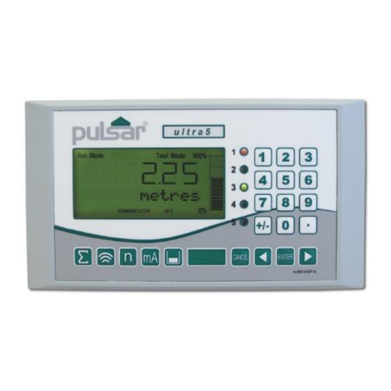
Ultra 5 Chapter 3 How To Use Your Operating the Controls Display The display provides information on the current mode of operation, and status of the remote communication. Whilst in the Run Mode it will display the current level reading and its units of measure, along with status messages with regards to the Transducer, Echo reception and Fail Safe Mode. -
Page 37: Run Mode
All modes are now described. Run Mode This mode is used once the Ultra 5 has been set up in program mode. It is also the default mode that the unit reverts to when it resumes operation after a power failure. -
Page 38: Program Mode
Program Mode This mode is used to set up the Ultra 5 or change information already set. You must use either the built-in keypad (standard) or, in the case of the rack and panel mount, the remote communicator (both keypads are identical in the way they operate). - Page 39 Align the arrows to activate the infra-red Once communications have been activated, you simply enter the passcode, via the keypad, followed by the ENTER key. The default passcode is 1997, so you would press the following: Note There is a time-out period of 15 minutes when in program mode, after which time run mode will be resumed if you do not press any keys.
- Page 40 Run Mode. Pressing the hot key once will display the first parameter, then repeated pressing will display the others, then the Ultra 5 reverts to Run Mode. In program mode, they have different functions, the functions are shown below.
- Page 41 1) Used to confirm each action (for example select a menu option) or when entering a parameter number or value. 2) Used to confirm questions asked by your Ultra 5 such as before restoring factory defaults. Used to navigate up a level in the menu system, and back to run mode.
- Page 42 When you have finished, press CANCEL to go back to the previous level. When you have reached the top level, then the Ultra 5 will ask for confirmation before allowing you to go back into run mode. This is done by pressing ENTER at the display prompt.
- Page 43 Note You can tell which part of the menu system you are in, as the up/down level indicators, (arrows) next to the bar graph will indicate as follows: • Top level menu: Down arrow on, to indicate you can move down. •...
-
Page 44: Test Mode
Test Mode Test mode is used to simulate the application and confirm that all parameters and relay setpoints have been entered as expected. During simulation, there is a choice of whether the relays will change state (hard simulation) or not (soft simulation), but the LED’s will always change colour as programmed, and the mA output will change in accordance to the chosen mode of operation. -
Page 45: Using The Rs232 Serial Interface
To log off, send the command /ACCESS:OFF To read a parameter value, send the command /Pxxx where xxx is the parameter you wish to read, and the Ultra 5 will respond with the parameter value. To set a parameter, send the command /Pxxx:yy where xxx is the parameter number, and yy is the value you wish to set it to. - Page 46 /BACKUP2 (take backup of parameters to area 2) /RESTORE1 (restore parameters from area 1) /RESTORE2 (restore parameters from area 2) Please consult Pulsar Process Measurement or contact your local Pulsar representative for further details and a full list of available commands. Page 38...
-
Page 47: Parameter Defaults
It will be indicating in metres, as shown on the display. All relays are set OFF. The date (P931) and time (P932) in Ultra 5 were set at the factory, but may need checking, and amending if, for example the application is in a time zone other than GMT, see relevant unit Parameter listing for full details. -
Page 48: Chapter 4 Ultra Wizard
Chapter 4 Ultra Wizard The Ultra Wizard menu allows you to turn Ultra 5 into anyone of three dedicated ultrasonic devices to exactly suit the requirements of your application. Ultra Wizard Menu To access the Ultra Wizard, you need to go from Run Mode to Program Mode. -
Page 49: Lev/Vol
If you require to set up a level or volume application, with or without a choice of control functions then press “1” followed by “ENTER” the message “Loading ***” will be displayed and your Ultra 5 will be configured as a Level Star 5. Confirmation that configuration has been... -
Page 50: Pump/Diff
If you require to set up a pump or differential application, then press “2” followed by “ENTER” the message “Loading ***” will be displayed and your Ultra 5 will be configured as an Advanced 5. Confirmation that configuration has been completed will be given by the unit type, software version and serial number being displayed briefly on the LCD and the unit advancing to the relevant “Quick Setup”... -
Page 51: Flow 5
For applications where there is no primary element, the optional 4-20mA input can be used to connect a Doppler Velocity Sensor (available from Pulsar) to enable the calculation of Flow Q = Velocity x area, for a wide range of channel shapes. Also, available within the unit is a customised 32-point calibration routine which also permits the flow measurement of non - standard flumes and weirs. -
Page 52: Chapter 5 Level / Volume
Chapter 5 Level / Volume When Ultra Wizard = 1 Level/Volume Ultra 5 is configured as a Level Star 5 This quick set-up guide shows you how to get up and running within a few minutes of installing your Level Star. - Page 53 Choose Your Application There are two categories of application, which are all described later in this chapter. They are level or volume all with the choice of control functions and alarms. If you want to set-up a basic level monitoring application, as described in the following example 1, then choose 1.
-
Page 54: Quick Setup Menu
The Quick Setup Menu detailing the questions you will be asked when setting up your Level Star, via the Quick Setup is shown below. Quick Setup Menu Quick Setup Application 1 = Level 2 = Volume 0 = No Control 1 = Control Down 2 = Control Up No. - Page 55 Wait …. Parameter Default Description P101 Transducer 2 = dB6 Type of transducer being used. P102 Material 1 = liquid Material in the vessel, either liquid or solid. If the solid lays flat, then it can be entered as liquid. P104 1 = metres Select units to be used for...
- Page 56 Parameter Default Description P213 / P214 Factory preset as a % Either Alarm or Level control. Relay 1 to appropriate level Depends on application. ON/OFF according to the span setpoints already entered. See tables below P223 / P224 Factory preset as a % Either Alarm or Level control.
- Page 57 The default values used for determining the relay setpoints, when setting Alarm and Control relays, via the Quick Setup menu are entered as a % of span and are as follows. Number of Cntl Relay Application Cntl Relays Number Setpoint Setpoint Cntl.
- Page 58 Relay Relay I.D. Function Setpoint Setpoint Alarm HiHi Alarm High Alarm Alarm LoLo Page 50...
-
Page 59: Example 1 Level Monitoring With Alarms
Example 1 Level Monitoring with Alarms A vessel, containing a liquid that has a variation in level that is to be monitored, with a high-level alarm set on Relay 1, and low level alarm set on Relay 2. empty distance (P105), 3.5m 100%, span (P106), 2.8m 85% , high alarm on (P213), 2.38m 80% , high alarm off (P214), 2.24m... - Page 60 To program the unit for Example 1 Level Monitoring with alarms by using the Quick Setup menu proceed as follows. If required access the Program Mode Key in the passcode 1997 and press ENTER Using the ‘right’ arrow key go to the Quick Setup menu press ENTER and as prompted, by the questions, select the relevant option and ENTER.
-
Page 61: Example 2 Level Monitoring And Control (Up Or Down)
Example 2 Level Monitoring and Control (up or down) A vessel, containing a liquid that has a variation in level that is to be monitored, and when the level reaches a specific point, the vessel is pumped down, with the fluid being transferred to another process. The pump will be assigned to Relay 1 a High Alarm to Relay 2 and Low Alarm to Relay 5. - Page 62 To program the unit for Example 2 Level Monitoring and Control by using the Quick Setup menu proceed as follows. If required access the Program Mode Key in the passcode 1997 and press ENTER Using the ‘right’ arrow key go to the Quick Setup menu press ENTER and as prompted, by the questions, select the relevant option and ENTER.
-
Page 63: Example 3 Volume Application
Example 3 Volume Application A cylindrical tank with a diameter of 2m and a flat base that is typically used to temporarily hold liquid, and you wish to know the volume of liquid. You also require a high and low alarm and when the level reaches a specific point, the vessel is pumped down, with the fluid being transferred to another process. - Page 64 To program the Level Star for Example 3 Volume Application with Control by using the Quick Setup menu proceed as follows. If required access the Program Mode Key in the passcode 1997 and press ENTER Using the ‘right’ arrow key go to the Quick Setup menu press ENTER and as prompted, by the questions, select the relevant option and ENTER.
- Page 65 Note If relay setpoints do not meet the exact requirements of the application, they can be modified to suit by pressing ENTER when, “For More Options Hit Enter”, is displayed and entering new values to relay setpoints as required. Alternatively, the relevant relay setpoint can be accessed either by the main menu system or directly via parameter number and changed as necessary.
-
Page 66: Menu System And Parameter Guide
Menu System and Parameter Guide This section outlines all parameters available in the Level Star, as they appear in the menu system. Shown below is a set of charts illustrating the menu system and location of all parameters available in the Level Star. For further details and full description of all parameters refer to Chapter 8 Parameter Listing and Descriptions. -
Page 67: Application Menu
Application Menu mA Input Operation Distances (Optional) P100 P104 P119 Mode Measurement mA Status Units P101 P120 Transducer Low mA In P105 Empty Level P121 P102 High mA In Material P106 Span P122 P103 Input 2 (Optional) Low Level In P107 Near Blanking P100 = 4 or 5... -
Page 68: Relays Menu
Relays Menu Relay 1 Relay 2 Relay 3 Relay 4 Relay 5 P210 P220 P230 P240 P250 Type Type Type Type Type P211 P231 P241 P251 P221 Function Function Function Function Function P232 P252 P212 P222 P242 Alarm ID Alarm ID Alarm ID Alarm ID Alarm ID... -
Page 69: Data Logs Menu
Data Logs Menu Temperature P580 Min. Temp P581 Min. Temp. Date P582 Min. Temp. Time P583 Max. Temp. P584 Max. Temp. Date P585 Max. Temp. Time P586 Current Temperature Page... -
Page 70: Volume Menu
Volume Menu Conversion Breakpoints Tables P600 P610 P696 Vessel Shape Level Bkpt. 1 Reset Bkpts. P611 P601 Vol. Bkpt. 1 As Required P697 Vol. Dimension 1 Number Bkpts. Set P612, 614, 616, 618, P602 620, 622, 624, 626, As Required 628, 630, 632, 634, Vol. -
Page 71: Display Menu
Display Menu Options Fail Safe Auxiliary Bargraph P808 P800 P810 P829 Display Fail Mode Units Bargraph Units P809 P811 P801 Fail Time Alarms Decimal Places P812 Pumps P802 Display P813 Offset Control P804 P814 Display Misc. Conversion P815 P805 Display Source Source P817... -
Page 72: Ma Output Menu
mA Output Menu Allocation Range Operation Setpoint Limits Trim Fail Safe P834 P831 P838 P840 P841 P830 P836 mA Out mA Out Fail Allocation Value Range Mode Limit Mode Trim P835 P836 High P838 High Value High Limit Trim Compensation Menu Offset Temperature Velocity... -
Page 73: Stability Menu
Stability Menu Damping Indicator Rate Filters P870 P872 P874 P880 Fill Fill Rate Update Gate Mode Damping Indicator P881 P875 Fixed Distance P871 P873 Rate Time Empty Empty Damping Indicator P882 P876 Process Filter Rate Distance P884 P877 Peak Percent Rate Value P878 Lower Cutoff... -
Page 74: Echo Processing Menu
Echo Processing Menu Xdr. 1 Status Xdr. 1 Status P900 P910 Xdr. 1 Status Xdr. 2 Status P901 P911 Echo Echo Confidence 1 Confidence 2 P902 P912 Echo Strength 1 Echo Strength 2 P903 P913 Average Noise 1 Average Noise 2 P904 P914 Peak Noise 1... -
Page 75: System Menu
System Menu Date Service System Daylight Passcode Backup & Alarm Info Colour Saving Time P926 P194 P921 P925 P931 P935 P970 Software Date Enable Code Parameter Date Revision Backup Colour Enable P922 P195 P932 P927 Passcode Interval Time P936 P971 Hardware (days) Alarm... -
Page 76: Device Comm Menu
Device Comm Menu RS232 RS485 Set Up Remote Set Up (Optional) Alarm If Comms. Type P061 If Comms. Type P144 PROFIBUS Comms Baud MODBUS Call Type P145 P130 Tel. No. 1 Device Mode P146 P131 Tel. No. 2 Protocol P132 P147 P132 Device Address... -
Page 77: Test Menu
Test Menu Simulation Hardware P980 P990 Simulate Self-Test P981 P991 Hardware Test Increment P992 P982 mA Out Test Rate P983 mA In Test Start Level (Optional) P984 P994 Incremental Transducer Test Change P995 Keys Test P996 Relay Test Page... -
Page 78: Chapter 6 Pump
Chapter 6 Pump When Ultra Wizard = 2 Pump/Differential Ultra 5 configured as an Advanced 5 This quick set-up guide shows you how to get up and running within a few minutes of installing your Advanced 5. Enter Program Mode First you need to go from run mode into program mode. - Page 79 Choose Your Application There are four categories of application, which are all described later in this chapter. They are level, pump down (sump control), pump up (reservoir control) or differential all with the choice of alarms. If you want to set-up a basic level monitoring application, as described in the following example 1, then choose 1.
-
Page 80: Quick Setup Menu
The Quick Setup Menu detailing the questions you will be asked when setting up your Advanced 5, via the Quick Setup is shown below. Quick Setup Menu Quick Setup 1 = Level 2 = Pump Down 3 = Pump Up 4 = Differential For each Control Number of Control... - Page 81 Wait …. Parameter Default Description P101 Transducer 2 = dB6 Type of transducer being used. P104 Select units to be used for 1 = metres Measurement programming measurement Units information. P105 Distance from the face of the Empty Level transducer to the material at the bottom of the vessel.
- Page 82 Parameter Default Description P830 2= 4 to 20 mA Determines the mA output mA Out Range range. 0 = Off, 1 = 0 to 20mA, 2 = 4 to 20mA, 3 = 20 to 0mA, 4 = 20 to 4mA. P870 10 m/min Rate of maximum fill rate (set...
- Page 83 Application Number of Pump Pumps Number Setpoint Setpoint Pump Up Pump 1 Pump Up Pump 1 Pump 2 Pump Up Three Pump 1 Pump 2 Pump 3 Pump Up Four Pump 1 Pump 2 Pump 3 Pump 4 Pump 1 Pump Up Five Pump 2...
- Page 84 Application Number of Cntl Relay Cntl Relays Number Setpoint Setpoint Level Control 1 Cntl. Up Level Control 1 Cntl. Up Control 2 Level Three Control 1 Cntl. Up Control 2 Control 3 Level Four Control 1 Cntl. Up Control 2 Control 3 Control 4 Level...
- Page 85 Relay Relay I.D. Function Setpoint Setpoint Alarm HiHi Alarm High Alarm Alarm LoLo Page...
-
Page 86: Example 1 Level Monitoring With Alarms
Example 1 Level Monitoring with Alarms A vessel, containing a liquid that has a variation in level that is to be monitored, with a high-level alarm set on Relay 1, and low level alarm set on Relay 2. empty distance (P105), 3.5m 100%, span (P106), 2.8m 85% , high alarm on (P213), 2.38m 80% , high alarm off (P214), 2.24m... - Page 87 To program the unit for Example 1 Level Monitoring with alarms by using the Quick Setup menu proceed as follows. If required access the Program Mode Key in the passcode 1997 and press ENTER Using the ‘right’ arrow key go to the Quick Setup menu press ENTER and as prompted, by the questions, select the relevant option and ENTER.
-
Page 88: Example 2 Sump Control (Pump Down)
Example 2 Sump Control (pump down) A sump is typically used to temporarily hold water or effluent, and when the level reaches a specific point, the sump is pumped down, with the fluid being transferred to another process. empty distance (P105), 3.5m 100%, span (P106), 2.8m 85% , high alarm on (P253), 2.38m 80% , high alarm off (P254), 2.24m... - Page 89 To program the Advanced 5 for Example 2 Sump control (pump down) using the Quick Setup menu proceed as follows. If required access the Program Mode Key in the passcode 1997 and press ENTER Using the ‘right’ arrow key go to Quick Setup menu press ENTER and as prompted, by the questions, select the relevant option and ENTER.
-
Page 90: Example 3 Reservoir Control (Pump Up)
Example 3 Reservoir Control (pump up) A reservoir is typically used to temporarily hold liquid, and when the level reaches a specific low point, the reservoir is pumped up. empty distance (P105), 3.5m 100%, span (P106), 2.8m 80%, pump 1+2 off (P214, 224), 2.24m 70%, pump 1 on (P 213), 1.96m 50%, pump 2 on (P 223), 1.4m 15% , low alarm off (P234), 0.42m... - Page 91 To program the Advanced 5 for Example 3 Reservoir Control (pump up) by using the Quick Setup menu proceed as follows. If required access the Program Mode Key in the passcode 1997 and press ENTER Using the ‘right arrow key go to Quick Setup menu press ENTER and as prompted, by the questions, select the relevant option and ENTER.
-
Page 92: Example 4 Differential Control
Example 4 Differential Control Pt 1 Pt 2 (Up stream) (Down stream) empty distance (P105), 3.5m 100%, span (P106), 2.8m 85% , Pt 1, high alarm on (P213), 2.38m 80% , Pt 1, high alarm off (P214), 2.24m 5%, Diff control, on, (223) 0.14m 1%, Diff. - Page 93 This will operate as follows, when the level rises on the upstream side and/or the level on the downstream side falls, resulting in a differential of 0.14m, (anywhere within the working span), indicating that the screen is blocked, relay 1 will come on and operate the rake. Once the level on the inflow has decreased and the differential level falls to 0.03m relay 1 will switch off the rake.
-
Page 94: Menu System And Parameter Guide
Menu System and Parameter Guide This section outlines all parameters available in the Advanced 5, as they appear in the menu system. Shown below is a set of charts illustrating the menu system and location of all parameters available in the Advanced 5. Further details and a full description of all parameters refer to Chapter 8 Parameter Listing and Descriptions. -
Page 95: Application Menu
Application Menu mA Input Operation Distances (Optional) P100 P104 P119 Mode Measurement mA Status Units P101 P120 Transducer Low mA In P105 Empty Level P121 P102 High mA In Material P106 Span P122 P103 Input 2 (Optional) Low Level In P107 Near Blanking P100 = 4 or 5... -
Page 96: Relays Menu
Relays Menu Relay 1 Relay 2 Relay 3 Relay 4 Relay 5 P210 P220 P230 P240 P250 Type Type Type Type Type P211 P231 P241 P251 P221 Function Function Function Function Function P232 P252 P212 P222 P242 Alarm ID Alarm ID Alarm ID Alarm ID Alarm ID... -
Page 97: Pump "Advanced" Menu
Pump “Advanced” Menu Run On Starting Stopping Exercise Wall Cling Storm P349 P352 P348 P354 P360 P370 Prime Start Exercise Pump Stop Delay Wall Cling Level Delay Enable Disable P350 P353 P355 P371 Power Idle Time Disable Interval Delay Time P356 P351 Exercise... -
Page 98: Data Logs Menu
Data Logs Menu Tot. Audit Temperature Pump 1 Pump 2 to 4 Pump 5 P460 P580 P516, P522 P510 P534 Vol. Date 1 P528 Min. Temp Pump 1 Pump 6 Pump Hours Hours Hours P461 P581 Volume 1 Min. Temp. P517, P523 P511 P535... -
Page 99: Pumped Volume Menu
Pumped Volume Menu Conversion Breakpoints Set Up Tables P600 P610 P205 P696 Vessel Shape Level Bkpt. 1 Pump Vol. Reset Enabled Bkpts. P601 P611 As Required Vol. Bkpt. 1 P206 P697 Vol. Dimension 1 Settle Time Number Bkpts. Set P612, 614, 616, 618, P602 620, 622, 624, 626, P207... -
Page 100: Efficiency Menu
Efficiency Menu Set Up P187 Pump Effic. P188 Calib. Delay P189 Cal. Duration P190 Persist Cnt. P191 Demote Pumps P192 Demote Flags P193 Calib. Pumps Page 92... -
Page 101: Display Menu
Display Menu Options Fail Safe Auxiliary Bargraph Totaliser P808 P800 P810 P829 P820 Display Fail Mode Units Bargraph Totaliser Units P809 P811 P821 P801 Fail Time Alarms Totaliser (R) Decimal Places P812 Pumps P822 P802 Total.Decimal Display P813 Offset Control P823 P804 Total. -
Page 102: Ma Output Menu
mA Output Menu Allocation Range Operation Setpoint Limits Trim Fail Safe P834 P830 P831 P836 P838 P840 P841 mA Out mA Out Fail Allocation Value Range Mode Limit Mode Trim P835 P836 High P838 High Value High Limit Trim Compensation Menu Offset Temperature Velocity... -
Page 103: Stability Menu
Stability Menu Damping Indicator Rate Filters P870 P872 P874 P880 Fill Fill Rate Update Gate Mode Damping Indicator P881 P875 P871 Fixed Distance Rate Time P873 Empty Empty Damping Indicator P882 P876 Process Filter Rate Distance P884 P877 Peak Percent Rate Value P878 Lower Cutoff... -
Page 104: Echo Processing Menu
Echo Processing Menu Xdr. 1 Status Xdr. 1 Status P900 P910 Xdr. 1 Status Xdr. 2 Status P901 P911 Echo Echo Confidence 1 Confidence 2 P902 P912 Echo Strength 1 Echo Strength 2 P903 P913 Average Noise 1 Average Noise 2 P904 P914 Peak Noise 1... -
Page 105: System Menu
System Menu Date Service System Daylight Passcode Backup & Alarm Info Colour Saving Time P926 P194 P921 P925 P931 P935 P970 Software Date Enable Code Parameter Date Revision Backup Colour Enable P922 P195 P932 P927 Passcode Interval Time P936 P971 Hardware (days) Alarm... -
Page 106: Device Comm Menu
Device Comm Menu RS232 RS485 Set Up Remote (Optional) Alarm Set Up P061 If Comms. Type If Comms. Type P144 Call Type Comms Baud MODBUS PROFIBUS P145 P130 Tel. No. 1 Device Mode P146 P131 Tel. No. 2 Protocol P147 P132 P132 Tel. -
Page 107: Test Menu
Test Menu Simulation Hardware P980 P990 Simulate Self-Test P981 P991 Hardware Test Increment P992 P982 mA Out Test Rate P983 mA In Test Start Level (Optional) P984 P994 Incremental Transducer Test Change P995 Keys Test P996 Relay Test Page... -
Page 108: Chapter 7 Flow
Chapter 7 Flow When Ultra Wizard = 3 Flow Ultra 5 configured as a Flow 5 This quick set-up guide shows you how to get up and running within a few minutes of installing your Flow 5. Enter Program Mode First you need to go from run mode into program mode. - Page 109 Choose Your Application There are six categories of Primary Measuring Device, which are all described in this chapter. They are exponential, BS3860 flumes, BS3860 weirs, area/velocity, special and universal. Calculations for flow can be performed using absolute or ratiometric calculations. The answer will be the same, the choice of calculation method being limited to the amount of information available, with regards to the primary measuring device.
- Page 110 For devices which do not match any of the above devices the application can be setup using a universal flow calculation, to select this option choose 6. You then need to select the primary measuring device for your application from the following available options: linear flow or curved flow. Once you have chosen your application you will be asked a series of questions which are answered by choosing the appropriate option as detailed in the flow chart below.
-
Page 111: Quick Setup Menu
The Quick Setup Menu detailing the questions you will be asked, when setting up your Flow 5, via the Quick Setup is shown below. Quick Setup Menu Quick Setup PMD Type 0 = Off (No Calculation) 1 = Exponential 2 = BS3680 Flumes 3 = BS3680 Weirs 4 = Not Available 5 = Special... -
Page 112: Volume Units
Wait …. Parameter Default Description P101 1 = dB Mach 3 Type of Transducer to be used. Transducer P706 Units of flow as on display and used 1 = Litres Volume Units for calculations. 1=litres 2 = cubic metres 3=cubic feet 4 = UK gallons 5=US gallons 6 = Mil.USG... - Page 113 Parameter Default Description P823 4=*1 Sets the factor by which the Totaliser calculated volume will be divided or Multiplier multiplied by before being displayed. 1 = /1000 2 = /100 3 = /10 4 = *1 5 = *10 6 = *100 7 = *1,000 8 = *10,000 9 = *100,000...
- Page 114 Parameter Set Value Description P213 / P214 depends on Set required Alarm Setpoints. Relay 1 application ON/OFF P223 / P224 depends on Set required Alarm Setpoints. setpoints Relay 2 application ON/OFF P233 / P234 depends on Set required Alarm Setpoints. setpoints Relay 3 application...
-
Page 115: Exponential Devices
Exponential Devices If the primary measuring device is a simple exponential device, then an exponent value is required. The Flow 5 will automatically enter the exponent value for the device chosen as detailed in the table below. Exponent Type Exponent P717 Suppressed Rectangular 1.50 Weir... -
Page 116: Point Of Measurement
Point of Measurement The transducer must be above the maximum head P704 by at least the near blanking distance P107. For Suppressed/Contracted Rectangular, Trapezoidal and V-notch, weirs, the head is measured upstream at a minimum distance of 3 times maximum head from the weir plate to ensure the surface of the liquid is not affected by turbulence or drawdown. - Page 117 For a Leopold Lagco flume the head is measured at a point upstream of the beginning of the converging section as detailed in the table below. (See DRWG 4 Flume Size Point of Measurement inches inches 100 - 305 4 - 12 1065 1220 1370...
-
Page 118: Calculations
Q=KLh 1.50 Automatically Rectangular Where: Automatically calculated, Weir Q =Flow selected by the dependent on (Without End K=K factor Ultra 5 measurement, Contractions) L=crest length of weir flow and time h=head units chosen. =exponent Cipolletti Q=KLh 1.50 Automatically (Trapezoidal) Where:... - Page 119 K Factor V-Notch Weir Q=Kh 2.50 Automatically Where: Automatically calculated, Q =Flow selected by the dependent on K=K factor measurement, Ultra 5 h=head flow and time =exponent units chosen. Other Q=Kh Enter value as Enter value as required required Contracted Q=K(L-0.2*h)h 1.50...
-
Page 120: Example 1 'V' Notch Weir
Example 1 ‘V’ Notch Weir In this example, it is required to calculate the flow through a Simple Exponential Device, which on this occasion is a V-Notch Weir. Ratiometric calculation will be used, there is no requirement for alarms and the flow rate is to be displayed in litres/second. - Page 121 To program the Flow 5 for Example 1 V-Notch Weir by using the Quick Setup menu proceed as follows. If required access the Program Mode Key in the passcode 1997 and press ENTER Using the ‘right’ arrow key go to the Quick Setup menu press ENTER and as prompted, by the questions, select the relevant option and press ENTER.
-
Page 122: Bs3680 Flumes
BS3680 Flumes Point of Measurement The transducer must be above the maximum head P704 by at least the near blanking distance P107. For a Rectangular and U-throated flume, the head is measured at 3 to 4 times the maximum head upstream from the beginning of the converging section, to ensure the surface of the liquid is not effected by turbulence. -
Page 123: Calculations
Calculations Rectangular Flume BSOLUTE If the flow calculation is to be absolute P702 = 1 the flow will be calculated using the formula: q = (2/3) Where: q = flowrate gn = gravitational acceleration (nominal value = 980.66 cm/s = shape coefficient (value = 1) = velocity coefficient calculated by the Flow 5 P721 = discharge coefficient calculated by the Flow 5 P722 b = throat width P711... - Page 124 U-Throated Flume BSOLUTE If the flow calculation is to be absolute P702 = 1 the flow will be calculated using the formula: q = (2/3) Where: q = flowrate = gravitational acceleration (nominal value = 980.66 cm/s h = head = shape coefficient calculated by the Flow 5 P724 = velocity coefficient calculated by the Flow 5 P721 = discharge coefficient calculated by the Flow 5 P722...
-
Page 125: Example 2 Bs3680 U-Throated Flume
Example 2 BS3680 U-Throated Flume In this example it is required to calculate to BS3680 the flow through a U- Throated Flume without any hump. Absolute calculation will be used, and there is a requirement for an alarm to indicate a low flow condition which will be set to relay 1. - Page 126 To program the Flow 5 for Example 2 BS3680 U-Throated Flume by using the Quick Setup menu proceed as follows. If required access the Program Mode Key in the passcode 1997 and press ENTER Using the ‘right’ arrow key go to the Quick Setup menu press ENTER and as prompted, by the questions, select the relevant option and press ENTER.
-
Page 127: Bs3680 Thin Plate Weirs
BS3680 Thin Plate Weirs Point of Measurement The transducer must be above the maximum head P704 by at least the near blanking distance P107. For Rectangular and V-notch weirs, the head is measured at a point 4 to 5 times the maximum head upstream from the weir plate, to ensure the surface of the liquid is not affected by turbulence or drawdown. - Page 128 ATIOMETRIC If the flow calculation is to be ratiometric P702 = 2 the flow will be calculated using the formula: q= q ecal ecal Where: q = flowrate = flowrate at maximum head P705 = discharge coefficient calculated by the Flow 5 P723 = discharge coefficient at maximum head = effective head = effective head at maximum head...
-
Page 129: Example 3 Bs3680 Rectangular Weir
Example 3 BS3680 Rectangular Weir In this example, it is required to calculate to the flow through a BS3680 Rectangular weir. Absolute calculation will be used, and there is a requirement for an alarm to indicate a high flow condition to be set to relay 3. - Page 130 To program the Flow 5 for Example 3 BS3680 Weir by using the Quick Setup menu proceed as follows. If required access the Program Mode Key in the passcode 1997 and press ENTER Using the ‘right’ arrow key go to the Quick Setup menu press ENTER and as prompted, by the questions, select the relevant option and press ENTER.
-
Page 131: Bs3680 Rectangular Broad Crested Weir
BS3680 Rectangular Broad Crested Weir Point of Measurement The transducer must be above the maximum head P704 by at least the near blanking distance P107. The head is measured at a point 3 to 4 times the maximum head upstream from the weir crest, to ensure the surface of the liquid is not affected by turbulence or drawdown. - Page 132 ATIOMETRIC BS3680 Rectangular Weir If the flow calculation is to be ratiometric P702 = 2 the flow will be calculated using the formula: q= q ecal ecal Where: q = flowrate = flowrate at maximum head P705 = discharge coefficient calculated by the Flow 5 P723 = discharge coefficient at maximum head = effective head = effective head at maximum head...
-
Page 133: Velocity Area
(Please consult Pulsar for availability). Point of Measurement The transducer must be above the maximum head P704 by at least the near blanking distance P107. -
Page 134: Calculations
Rectangular Channel Calculations BSOLUTE Rectangular and U-Channel If the flow calculation is to be absolute P702 = 1 the flow will be calculated using the formula: q = v x b x h Where: q = flowrate v = velocity b = channel width/diameter (Dim “A”) P710 h = head Page 126... - Page 135 Trapezoidal If the flow calculation is to be absolute P702 = 1 the flow will be calculated using the formula: q = vh (b + mh) Where: q = flowrate v = velocity h = head b = base width (Dim “B”) P711 m = side slope calculated from m = (B -b)/d where B = channel top width (Dim “A”) P710, b = base width (Dim “B”) P711...
- Page 136 Round Pipe If the flow calculation is to be absolute P702 = 1 the flow will be calculated using the formula: q = va(h) Where: q = flowrate = velocity a(h) = area at head Page 128...
-
Page 137: Special Devices
Special Devices Point of Measurement The transducer must be above the maximum head P704 by at least the near blanking distance P107. In the case of a Palmer Bowlus flume the point of head measurement should be half the value of Dim “A” P710 upstream of the device. For a H-Flume the head measurement is taken at a point downstream from the flume entrance as detailed in the table below: Flume size... -
Page 138: Calculations
V-notch angle weirs, the head is measured upstream of the weir plate at a minimum distance of 3 times maximum head to ensure the surface of the liquid is not effected by turbulence or drawdown. See Exponential devices, above, for further details. Calculations Palmer Bowlus Flume and H-Flume BSOLUTE... -
Page 139: Universal Calculations
ATIOMETRIC V-Notch Angle Weir (Non-BS 3680) If the flow calculation is to be ratiometric P702 = 2 the flow will be calculated using the formula: q= q (h+kh/h +kh) Where: q = flowrate = flowrate at maximum head P705 = head kh = compensated head Universal Calculations Point of Measurement... -
Page 140: Menu System And Parameter Guide
Menu System and Parameter Guide This section outlines all parameters available in the Flow 5, as they appear in the menu system. Shown below is a set of charts illustrating the menu system and location of all parameters available in the Flow 5. For further details and full description of all parameters refer to Chapter 8 Parameter Listing and Descriptions. -
Page 141: Application Menu
Application Menu mA Input Operation Distances (Optional) P100 P104 P119 Mode Measurement mA Status Units P101 P120 Transducer Low mA In P105 Empty Level P121 P102 High mA In Material P106 Span P122 Low Level In P107 Near Blanking P123 High Level In P108 Far Blanking... -
Page 142: Relays Menu
Relays Menu Relay 1 Relay 2 Relay 3 Relay 4 Relay 5 P210 P220 P230 P240 P250 Type Type Type Type Type P211 P231 P241 P251 P221 Function Function Function Function Function P232 P252 P212 P222 P242 Alarm ID Alarm ID Alarm ID Alarm ID Alarm ID... -
Page 143: Data Logs Menu
Data Logs Menu Totaliser Temperature Audit P580 Min. Temp P460 Total Date 1 P581 Min. Temp. P461 Date Totaliser 1 P582 P462, 464, Min. Temp. 466, 468, 470, Time 472, 474, 476 Total Dates 2 to 9 P583 P463, 465, Max. -
Page 144: Ocm
Break Average Dimensions Calcs Tables Velocity Setup Points Flow P700 PMD P710 P730 P796 P863 P726 P720 Dimension “A” Type Head Reset Average Area B’points Bkpt. 1 Flow mA In P701 P721 P711 P864 P731 P797 P727 Primary Dimension “B” Calc. -
Page 145: Display Menu
Display Menu Options Fail Safe Auxiliary Bargraph Totaliser P800 P808 P810 P829 P820 Display Fail Mode Units Totaliser Bargraph Units P809 P811 P801 Fail Time P821 Alarms Decimal Totaliser Places P812 Pumps P802 P822 Display P813 Totaliser Offset Control Decimal P804 P814 Display... -
Page 146: Compensation Menu
Compensation Menu Offset Temperature Velocity P851 P852 P860 Measurement Temperature Sound Offset Source Velocity P854 Fixed Temperature Stability Menu Damping Indicator Rate Filters P870 P872 P874 P880 Fill Fill Rate Update Gate Mode Damping Indicator P875 P881 P871 P873 Rate Time Fixed Distance Empty Empty... -
Page 147: Echo Processing Menu
Echo Processing Menu Xdr. 1 Status P900 Xdr. 1 Status P901 Echo Confidence P902 Echo Strength P903 Average Noise P904 Peak Noise P905 Sensitivity P906 Side Clearance Page... -
Page 148: System Menu
System Menu Date Service System Daylight Passcode Backup & Alarm Info Colour Saving Time P926 P194 P921 P925 P931 P935 P970 Software Date Enable Code Parameter Date Revision Backup Colour Enable P922 P195 P932 P927 Passcode Interval Time P936 P971 Hardware (days) Alarm... -
Page 149: Device Comm Menu
Device Comm Menu RS232 RS485 Set Up Remote Set Up (Optional) Alarm If Comms. Type P061 If Comms. Type P144 PROFIBUS Comms Baud MODBUS Call Type P145 P130 Tel. No. 1 Device Mode P146 P131 Tel. No. 2 Protocol P147 P132 P132 Tel. -
Page 150: Test Menu
Test Menu Simulation Hardware P980 P990 Simulate Self Test P981 P991 Hardware Test Increment P992 P982 mA Out Test Rate P983 mA In Test Start Level (Optional) P984 P994 Incremental Transducer Test Change P995 Keys Test P996 Relay Test Page 142... - Page 151 This page left blank intentionally Page...
-
Page 152: Chapter 8 Parameter Listing And Descriptions
Chapter 8 Parameter Listing and Descriptions Application Parameters Operation P100 Mode of Operation This parameter sets the mode of operation, when in run mode, and can be set to one of the following: Option Description When Ultra Wizard = 1 Level/Vol., 2 Pump/Diff. or 3 Flow Display shows the distance from the 1 = Distance (Default) transducer face to the surface. - Page 153 Option Description When Ultra Wizard = 1 Level/Vol. or 2 Pump/Diff. 0=Auxiliary Use the optional mA input (Please consult Pulsar (Optional) for availability). 1 = dB3 Transducer is a dB3. Range 0.125 to 3.00 metres Transducer is a dB6.
-
Page 154: Dimensions
P103 Input 2 (Optional) The 4-20 mA input is available as an option (Consult Pulsar for details of availability), and can be used to replace the transducer for applications where an ultrasonic transducer cannot be used. Use this parameter to set the second input device when using in Average or Differential Mode, and P101 Transducer = 1 (Optional Auxiliary Input). - Page 155 Important Information When changing the Empty Distance (P105) you can also recalculate the values for the Span so that it equals the empty distance (P105) minus Near Blanking (P107) and the Relay Setpoints, so that they remain at the same percentage values of the empty distance as they were before you changed the empty distance (P105).
-
Page 156: Ma Input
This parameter is always entered as a % of empty level. mA Input The 4-20 mA (Auxiliary) input is available as an option (Consult Pulsar for details of availability), and can be used to replace the transducer for applications where an ultrasonic transducer cannot be used. - Page 157 (Aux. input) instead of an ultrasonic transducer. P124 Low mA Trim This parameter allows you to “calibrate” the Ultra 5 to the Low mA Input from the device being used. If the expected low value, from the device connected to the mA Input, is not displayed, then you can trim it using this parameter.
-
Page 158: Relay Parameters
Relay Parameters All relay related parameters are prefixed with a 2**. The second digit of the three-figure parameter number denotes the relay number as follows: 21* parameters for Relay 1 22* parameters for Relay 2 23* parameters for Relay 3 24* parameters for Relay 4 25* parameters for Relay 5 The third digit selects specific parameter for the setting of the relays, which... - Page 159 P210, P220, P230, P240, P250 - Relay Type This parameter defines what type each relay should be, see the table below for available options. Option Description Relay not in use or programmed and LED 0= Not In Use (Default) will always be off. Relay is programmed as an alarm relay, 1= Alarm which will de-energise ON, and energise...
-
Page 160: Alarms
Alarms P210, 220, 230, 240, 250 =1 (Alarm) The second parameter for each relay determines the function of the alarm. P211, P221, P231. P241, P251 - Relay Function This parameter defines what function the alarm will respond to as follows. Option Description Relay will not operate. - Page 161 14= Service Alarm Alarm is raised when the service alarm date/time interval expires. This is set in ‘System > Service Alarm > Date (P194) > Interval (P195)’. The (Only available in firmware version alarm trigger is automatic in the unit and is set at 7.4.3 and greater) 12 noon, meaning that the alarm will activate at 12 noon on the date programmed into the unit...
- Page 162 Alarm ID Description Setpoints Relay goes “ON” when 4= Low ON<OFF Relay the value lowers to the Setpoints ON setpoint and goes P213, 223, 233, “OFF” when the value 243, 253 and P214, rises to the OFF setpoint. 224, 234, 244, 254. Setpoints, can be set in any order as the unit ‘knows’...
- Page 163 The fourth parameter and the fifth parameter for each relay set the Alarm “ON” and “OFF” points. For a high alarm the “ON” is set higher than “OFF”. For low alarm then “ON” is set lower than “OFF”. See the appropriate alarm ID, table (P212, 222, 232, 242, 252) for further information.
-
Page 164: General Control
General Control When Ultra Wizard = 1 Level/Volume P210, 220, 230, 240, 250 =2 (General Control) When a relay is being used for a general control function, the second parameter determines whether the control is currently switched “ON” or “OFF”. P211, P221, P231, P241, P251 - Relay Function This parameter defines whether the general control relay function is currently “ON”... -
Page 165: Pumps
P214, P224, P234, 244, 254 - Relay Setpoint 2 This parameter determines the “OFF” point for the general control relay, the Relay Setpoints are entered in values of Measurement Units (P104) P219, P229, P239, 249, 259 - Relay Max.Rate This parameter will allow a General Control Relay to be switched at a pre- determined Rate of change of Level, irrespective of the “ON”... - Page 166 Pump Duty Description 3= Alternate duty assist All pumps are used to assist each other (run at the same time). Each pump has its own setpoints, (P213, 223, 233, 243, 253 & P214, 224, 234, 244, 254) but each time all pumps have stopped, the setpoints are sequentially rotated between the pumps to ensure equal pump use.
- Page 167 Pump Duty Description 6= Service ratio duty assist All pumps are used to assist each other (run at the same time) and each pump has its own setpoints (P213, 223, 233, 243, 253 & P214, 224, 234, 244, 254). And a service ratio setting. The third setpoint (P215, 225, 235, 245, 255) is used to set the service ratio.
- Page 168 Pump Duty Description 9 = Service Ratio Standby When a service ratio duty is being used, on all other pumps in use, the standby pump can be started on a ratio basis only, when it will assume the setpoints of the next pump to start. The third setpoint (P215, 225, 235, 245, 255) is used to set the service ratio.
- Page 169 This parameter determines the “OFF” point for the pump. The sixth parameter will determine the service ratio that will be used to switch the pump, when pump duty selected is a Service Ratio duty. P211, 221, 231, 241, 251 = 6, 7 or 9 (Service ratio) P215, P225, P235, P245, P255 - Relay Setpoint 3 This parameter determines the Service Ratio in values of %.
-
Page 170: Control
Control P210, 220, 230, 240, 250 = 3 (Control) When a relay is being set up as a control relay, the second parameter that will be displayed in the menu determines its function. P211, P221, P231, P241, P251, Relay Function, This function allows the relay to be assigned to specific control functions (other than pumps and alarms) several of these functions work in relation to time. - Page 171 Options Description Relay will energise “ON” after each Cycle 3 = Aeration time as set in Relay Setpoint 2 (P214, 224, 234, 244, 254). And turns “OFF”, de- energises, after the set On Time Period as set in Relay Setpoint 1 (P213, 223, 233, 243,253).
- Page 172 Options Description 5=Step Time Step Time Control allows relays to be used to control a device, such as a motorised valve or gate, in order to maintain the level within two predetermined points. Relays will energise “ON” when Step Time condition is in effect and de-energises “OFF”...
- Page 173 The third parameter for each relay determines the assignment or condition of the relay, where required. P212, P222, P232, P242, P252 - Relay Alarm ID/Pump Group When Ultra Wizard = 2 Pump Differential P211, 221, 231, 241, 251 = 1, 2, 3 or 6 This parameter has no function and will not be displayed.
- Page 174 The fourth parameter, fifth parameter and sixth parameter are set to determine the switch points, “ON” and “OFF” for the relay and where required the order of start. See control function, table (P211, 221, 231) for further information. When Ultra Wizard = 2 Pump/Differential P213, P223, P233, P243, P253 Relay Setpoint 1 P211, 221, 231, 241, 251 =1 (Time) This parameter determines the “Time Period”...
- Page 175 P214, P224, P234, P244, P254 Relay Setpoint 2 P211, 221, 231, 241, 251 =1 (Time) This parameter determines the “Cycle Time ” for the operation of the relay. See the appropriate relay Function tables (P211, 221, 231, 241, 251) for further information.
- Page 176 P215, P225, P235, P245, P255 Relay Setpoint 3 P211, 221, 231, 241, 251 = 4 (Flush Valve) Enter desired Flush duration in seconds. See the appropriate relay Function tables (P211, 221, 231, 241, 251) for further information. P211, 221, 231, 241, 251 = 5 (Step Time) This parameter is used to determine the Limit Time between each Drive Period.
-
Page 177: Miscellaneous
Miscellaneous P210, 220, 230, 240, 250 = 4 (Miscellaneous) When a relay is set to be a miscellaneous relay, the second parameter determines its function. P211, P221, P231, P241, P251 - Relay Function This function allows the relay to work in relation to a clock or a specific event and will be set to activate in relation to Real Time. - Page 178 The third parameter has no function when miscellaneous relay is chosen and will not be displayed. The fourth parameter, and fifth parameter, are set to determine the switch points, “ON” and “OFF” for the relay. See miscellaneous function table (P211, 221, 231, 241, 251) for further information. P211, 221, 231, 241, 251 = 1 (Clock) P213, P223, P233, P243, P253 - Relay Setpoint 1 Relay Setpoints are entered in Hours &...
-
Page 179: Pump By Time
Pump by Time When Ultra Wizard = 2 Pump/Differential When a relay is assigned to Pump by Time the pump will come on (energise) at its normal “ON” level setpoint, and de-energise at its OFF level setpoint or after a predetermined time period, whichever occurs first. P210, 220, 230, 240, 250 = 5 (Pump by Time) When a relay is being used for a pump by time function, the second parameter determines the pump duty that will be used to determine the... - Page 180 Pump Duty Description 4= Alternate duty backup If a pump fails to meet the demand (due to malfunction, intake blockage etc.), then it is stopped and another pump shall take over. Each pump has its own setpoints, (P213, 223, 233, 243, 253 & P214, 224, 234, 244, 254) but each time all pumps have stopped, then the setpoints are sequentially rotated...
- Page 181 The fourth parameter, and the fifth parameter for each relay set the pump “ON” and “OFF” points, which are entered in Measurement units P104. For pump down the “ON” is set higher than “OFF”. For pump up then “ON” is set lower than “OFF”. See the appropriate pump duty, function table (P212, 222, 232, 242, 252) for further information.
-
Page 182: Common Parameters
P217, P227, P 237, P247, P257 - Relay Closures The Ultra 5 will record how many times each relay is closed, this parameter displays the number of times the relay has activated since the relay has been in use. -
Page 183: Pump "Advanced" Parameters
Pump “Advanced” Parameters When Ultra Wizard = 2 Pump/Differential The following parameters are used to set the “Advanced” Pump features. Pump Run On This feature is used to periodically allow the pumps to continue operating below their normal “OFF” point, in order to discharge any sediment that may have settled at the bottom of the vessel. -
Page 184: Stopping
Stopping If required, this feature will prevent pumps, with a common “OFF” point being switched off all at the same time pumps will be switched “OFF” in turn as determined by the delay set in P348 Stop Delay. P348 Stop Delay Set the required time period, in seconds, that should elapse between pumps stopping. -
Page 185: Wall Cling
Wall Cling To reduce material build up (such as fat), on the wall of the sump or vessel, at the “normal” material level the pump setpoints can be varied within a specified band. For Pump Down applications the relay setpoints for the pumps will be randomly varied within the band specified, somewhere below ON, but to a maximum of the setting, and somewhere higher than OFF, but to a maximum of the setting. -
Page 186: Data Log Parameters
Data Log Parameters The data log parameters contain the following information. Totaliser Audits When Ultra Wizard = 2 Pump/Differential Pump Volume Enabled P205 = 1 When Ultra Wizard = 3 P460 to P479 Total Audits Parameters P460-P479show the date and pumped volume total for the last ten days, the first on the list are the most recent and last ones are the oldest. - Page 187 P582 Minimum Temperature Time This parameter displays the time when the minimum temperature was recorded. P583 Maximum Temperature This parameter displays the maximum temperature recorded. P584 Maximum Temperature Date This parameter displays the date when the maximum temperature was recorded. P585 Maximum Temperature Time This parameter displays the time when the maximum temperature was recorded.
-
Page 188: Pump Logs
Pump Logs When Ultra Wizard = 2 Pump/Differential P510 Pump 1 Hours This parameter displays the current total running hours for Pump 1. Any value from 0 - 9999 can be entered to facilitate any update to the stored total for any reason e.g. -
Page 189: Pumped Volume
P522 - P527 Pump 3 These parameters contain the same information as above for Pump 3. P528 - P533 Pump 4 These parameters contain the same information as above for Pump 4. P534 - P539 Pump 5 These parameters contain the same information as above for Pump 5. Pumped Volume When Ultra Wizard = 2 Pump/Differential Set Up... -
Page 190: Volume
Volume When Ultra Wizard = 1 Level/Volume or 2 Pump/Differential Your Ultra 5 provides a variety of volume calculation features, with 11 pre- programmed vessel shapes. See Vessel Shape (P600) for more information. For each vessel, you will need to know the dimensions (P601-603) in Measurement Units (P104) which are required to calculate the volume (P604) which will be displayed in the selected Volume Units (P605). - Page 191 Vessel Shape P600 Value Dimensions P600=4 Cylindrical Cylinder diameter Required and height of Parabola base bottom P600=5 Cylindrical Cylinder Diameter Half-sphere base P600=6 Cylindrical Cylinder diameter Flat sloped base and height of bottom P600=7 Rectangular Width and Breadth Flat sloped base of rectangular section and height of bottom...
- Page 192 P604 Calculated Volume This parameter displays the maximum volume that has been calculated by the Ultra 5 and is a Read-Only parameter. The volume displayed will be shown in volume units (P605) and is the total volume available between empty level (P105) and 100% of span (P106).
-
Page 193: Breakpoints
P607 Max Volume This parameter displays the actual maximum volume that has been calculated by the Ultra 5, i.e. P604 Calculated Volume x P606 Correction Factor, and is a Read-Only parameter. The volume displayed will be shown in P605 Volume Units and is the total volume available between empty level (P105) and 100% of span (P106). - Page 194 Universal Linear (P600=11) This volume calculation creates a linear approximation of the level/volume relationship, and works best if the vessel has sharp angles between each section. Level You should enter a level/volume breakpoint for each place where the vessel changes direction, and numerous where the section is slightly curved (mostly linear, but has got a small arc).
-
Page 195: Tables
Tables P696 Reset Breakpoints This parameter allows the resetting, to the default value, of all previously set breakpoints (P610-673), without having to access them individually. When it is necessary to reset or amend particular breakpoints this can be achieved by directly accessing the desired parameter (P610-673) and changing as required. - Page 196 P189 Cal. Duration This parameter sets the time duration over which the pumps performance will be monitored and the resulting efficiency is calculated. Important Information When setting the time period for the Calibration Duration (P189) it is important that it does not exceed the time from one pump Start to the next pump Start during normal operation as it will abort any subsequent calculation of Efficiency.
- Page 197 P192 Demote Flags This parameter will indicate, in a binary number format as detailed below, which pumps, if any, have been demoted. Any demoted pump(s) can be reset by entering “0”. 0 = None 16 = Pump 5 1 = Pump 1 17 = Pump 1 + 5 2 = Pump 2 18 = Pump 2 + 5...
-
Page 198: Ocm Parameters
OCM Parameters When Ultra Wizard = 3 Flow PMD Setup P700 Primary Measuring Device Type This parameter is used to select the type of Primary Measuring Device and enable additional parameters required to calculate the flow of the Primary Measuring Device chosen (P701). Options are as follows: 0 = Off (Default) 1 = Exponent 2 = BS3680 Flume... - Page 199 (Please consult Pulsar for availability). Select from the following options: 1 = Circular Straight (U-Channel), circular bottom, straight sides.
- Page 200 P702 Calculation Select the required calculation method, both will give the same answer, but the difference is the information required to complete the calculation. For ratiometric it is normally sufficient to know the maximum flow at the maximum head. Choose between: 1 = Absolute 2 = Ratiometric (Default) P703 Minimum Head...
- Page 201 P706 Volume Units Select the Volume Units to be used to display and calculate the flow rate from the options below: Option Description 1= Litres (Default) Flow will be calculated and displayed in Litres 2= Cubic metres Flow will be calculated and displayed in Metres 3= Cubic feet Flow will be calculated and displayed in Feet 4= UK Gallons...
-
Page 202: Dimensions
Dimensions P710 Dimension A This parameter is used to enter dimension “A” of the Primary Measuring Device, where applicable, see table below for further details. P711 Dimension B This parameter is used to enter to enter dimension “B” of the Primary Measuring Device, where applicable, see table below for further details. - Page 203 P710 P711 P712 P713 Primary Measuring Device Dim “A” Dim “B” Dim “C” Dim “D” P700 = 4 Area Velocity Channel P701 = 2 Rectangular Width Required Required Required Channel Channel P700 = 4 Area Velocity Channel Width Width P701 = 3 Trapezoidal Depth Required Bottom...
- Page 204 P714 Roughness Coefficient (Ks) When P700 = 2, BS3680 Flume this parameter is used to enter the roughness coefficient of the flume in millimetres, see table below for further details. Value of Ks Good Normal Surface Classification Example Value Plastics, etc. Perspex, PVC or other smooth faced 0.003 plastics...
-
Page 205: Calculations
P717 Exponent This parameter is used to enter the exponent value when: P700 PMD Type = 1 Exponent and P701 Primary M.D = 7 Others. P718 K Factor This parameter is used to enter the K Factor when: P700 PMD Type = 1 Exponent and P702 Calculation = 1 Absolute see table below for further details. -
Page 206: Velocity
(Please consult Pulsar for availability). Parameters P726 to P729 are used to configure the optional 4 -20mA input for a velocity sensing device. When an Area/Velocity application is selected... -
Page 207: Breakpoints
P728 Low Vel. In This parameter sets the minimum velocity, at low mA In (P726) when the current input is allocated to a velocity input device. Default = 0m/sec. P729 High Vel. In This parameter sets the maximum velocity, at High mA In (P727) when the current input is allocated to a velocity input device. -
Page 208: Average Flow
Average Flow P863 Average Flow This parameter will display the Average Flow for the time period set in Average Time (P864). It is read only and cannot be changed. P864 Average Time This parameter will set the time period over which the Average Flow (P863) is to be calculated before being displayed. -
Page 209: Failsafe
P804 Display Conversion The reading is multiplied by the value of this parameter before being displayed. The default is 1.0, but if for example you wanted to display the reading in yards, then set the Measurement Units (P104) to feet, and set P804 to 3. -
Page 210: Auxiliary
Important Information In the event of a fail-safe condition occurring, the display, relays and mA Output can be configured to fail to a condition which is independent of each other. To set independent Relay Failsafe see P218, 228, 238, 248, 258. And for independent mA Output Failsafe see P840. - Page 211 P812 General Control or Pump Messages This parameter determines whether notification messages are displayed on the auxiliary line of the display in run mode when a pump or general control relay is switched on or off. The message is in the form “General 1 ON”, where the number displayed is the number of the relay.
-
Page 212: Totaliser
P815 Auxiliary Source When Ultra Wizard = 1 Level/Volume or 2 Pump/Differential When P100 = 4 (Average) or 5 (Differential) the auxiliary display line can be used to display the level on any of the two points of measurement. The options are as follows: Option Description 0 = Off (Default) - Page 213 P821 Totaliser (R) Displays the current value of the, resettable totaliser. This totaliser can be allocated to appear, during run mode, on the auxiliary display line (P816) or alternatively via the “Totaliser” hot key. P822 Totaliser Decimal Places This parameter determines the number of decimal places in the totaliser during run mode.
-
Page 214: Bargraph
Bargraph P829 Bargraph By default, the bar graph will be representative of the reading obtained, as determined by the Mode P100. When P100 = 4 (Average) or 5 (Differential) the bar graph can be assigned to be representative of the level on any of the two points of measurement. -
Page 215: Ma Output Parameters
mA Output Parameters Range P830 mA Range This parameter determines the range of the mA output, from the following. Option Description 0= Off mA output disabled. mA output directly proportional to the mA mode 1= 0 to 20 mA (P831), so if the reading is 0% the output is 0 mA. If the reading is 100% the output is 20 mA. -
Page 216: Setpoint
Option Description When Ultra Wizard = 2 Pump/Differential 4 = Avg. Level mA output is relative to the average level of two points of measurement. P100 = 4 mA output is relative to the differential 5 = Differential between two points of measurement P100 = 5 When Ultra Wizard = 3 Flow 4 = OCM Head mA output is relative to OCM head. -
Page 217: Trim
P837 mA High Limit This parameter sets the highest level that the mA output will rise to, the default is 20 mA, but you can override this if the device you connect to cannot for example accept more than 18 mA, yet you want to use the 0-20 mA range. -
Page 218: Allocation
Allocation P841 mA Allocation By default, the mA output will be representative of the reading obtained, as determined by the Mode P100. When P100 = 4 (Average) or 5 (Differential) the mA output can be assigned to be representative of the level of either of the two points of measurement This parameter is automatically set to the correct default option when selecting the Mode P100 and Xducer (P101), and under normal circumstances will not require... -
Page 219: Temperature
P853 Allocation When Ultra Wizard = 1 Level/Volume or 2 Pump/Differential This parameter indicates which transducer is being used to obtain the temperature, in the case of the Ultra 5 this can be viewed but cannot be changed. Option Description 0 = Xducer 1 (Default) Temperature obtained from Xducer 1. -
Page 220: Velocity
With the material at a steady level, view the value of P861 or P862, which will indicate the current distance as calculated by the Ultra 5 with respect to the current Velocity P860. Physically measure the distance from the face... -
Page 221: Stability Parameters
Stability Parameters Damping Damping is used to damp the display, to enable it to keep up with the process but ignore minor surface fluctuations. P870 Fill Damping This parameter determines the maximum rate at which the unit will respond to an increase in level. It should be set slightly higher than the maximum vessel fill rate. -
Page 222: Filters
Please consult Pulsar for further information and assistance on changing the value of this parameter, Default = 0 (Fixed) -
Page 223: Echo Processing Parameters
“angles of repose” presented by the way the material settles. Please consult Pulsar, for further information and assistance on changing the value of this parameter. Echo Processing Parameters... -
Page 224: Transducer 2 Status
P905 Sensitivity This parameter determines the sensitivity of the unit. Please consult Pulsar for further information and assistance on changing the value of this parameter. -
Page 225: System Parameters
Restore all parameters from area 2 System Information The following three parameters do not affect how the unit performs, but details, contained in them, may be required, by Pulsar, when making technical enquiries. P926 Software Revision This parameter will display the current software revision. It is read only, and cannot be changed. -
Page 226: Date & Time
P927 Hardware Revision This parameter will display the current hardware revision. It is read only, and cannot be changed. P928 Serial Number This parameter will display the serial number of the unit. It is read only, and cannot be changed. The serial number can also be viewed while in RUN mode by pressing the decimal point key. -
Page 227: Led Colour
P933 Date Format This parameter allows you to alter the format that the date is displayed to your choice of DD: MM: YY, MM: DD: YY or YY: MM: DD. The default is DD: MM: YY. LED Colour Each relay has an associated LED, located on the unit’s front panel, which indicates the status of the relay. -
Page 228: Watchdog
This can be useful if there have been power failures or if for any reason the Ultra 5 restarts due to a fault condition. The Ultra 5 can be backed up from a battery which automatically cuts in during power failure, battery backed up units will continue uninterrupted operation and therefore will not register a loss of mains power. - Page 229 P972 DST Start Time This parameter is used to set the time of day at which Daylight Saving Time will start, the time is entered in the format HH: MM (24-hour format). Default = 02:00 P973 Start Day Use this parameter to enter the day of the week (P974) that Daylight Saving Time is to start.
- Page 230 P975 Start Month This parameter is used to select the month, in which Daylight Saving Time will start. Option Description 1= January DST will start during the month of January 2= February DST will start during the month of February 3=March (Default) DST will start during the month of March 4= April...
- Page 231 P978 End Week This parameter will determine the week of the month (P975) in which Daylight Saving Time is to end. Option Description 1= Week 1 DST will end on day (P977) in the first week (P978) of the month (P979). 2= Week 2 DST will end on day (P977) in the second week (P978) of the month (P979).
-
Page 232: Service Alarm
Service Alarm This feature is only available in units with firmware version 7.4.3 or greater. P194 Date This parameter allows you to set the date when the service will be due i.e. 19/04/15. This will change automatically after a reset (P199) to the new date, as set in ‘Interval’... -
Page 233: Device Comm
Ultra 5 so that when the level reaches a specific alarm point, as determined by the setting of the relay(s) the unit will dial and connect to a remote telephone number to provide details of the event. - Page 234 2= SMS This option initiates a predetermined message which is sent to the remote telephone number detailing date and time the alarm was initiated, the site ID, alarm condition and level at the time the alarm was initiated. Page 226...
- Page 235 P145 Tel. No.1 This parameter is used to enter the number of ‘0’s that appear at the beginning of the telephone number to be dialled that is to receive the message. Option Description No ‘0’s present at the beginning of the 0= None telephone number to be dialled.
-
Page 236: Test Parameters
Test Parameters Simulation P980 Simulate Test mode is used to simulate the application and confirm that all parameters and relay setpoints have been entered as expected. During simulation, there is a choice of whether the relays will change state (hard simulation) or not (soft simulation), but the LED’s will always change colour as programmed, and the current output will change. -
Page 237: Hardware
P982 Rate In automatic mode, the rate at which the level will move up and down is determined by distance, P981 Increment and the time, P982 Rate which by default is set to 1min and can be changed as required. To increase the rate at which the level moves increase the Increment (P981) or decrease the Rate (P982). - Page 238 • Keys. You should press each key, to confirm it works, with a counter showing how many more keys you have to press. Be sure to press the CANCEL key last, as this will show if all keys were pressed or not. If they were not, then an error message is displayed. P992 mA Out Test This parameter will allow you to force a specified current on the mA output, to test the equipment that it is connected to, and to make sure the unit is...
-
Page 239: Chapter 9 Troubleshooting
Chapter 9 Troubleshooting This section describes many common symptoms, with suggestions as to what to do. Symptom What to Do Display blank, transducer not firing. Check power supply, voltage selector switch and fuse. Displays “No Xducer” Check wiring to transducer. Displays “Xducer Flt”... - Page 240 This page left blank intentionally Page 232...
-
Page 241: Parameter Record
Parameter Record PPLICATION Operation Parameter Details Entered Values Description Default P100 Mode 1 = Dist. P101 Xducer 2 = dB6 P102 Material 1= Liquid P103 Input 2 0 = None Distances Parameter Details Entered Values Description Default P104 Measurement Units 1=metres P105 Empty Level... - Page 242 ELAYS Relay 1 Parameter Details Entered Values Description Default P210 R1 Type 0 = Off P211 R1 Function 0 = Off P212 R1 Alarm ID 1 = Off P213 R1 Set 1 0.000 metres P214 R1 Set 2 0.000 metres P215 R1 Set 3 0.000...
- Page 243 Relay 4 Parameter Details Entered Values Description Default P240 R4 Type 0 = Off P241 R4 Function 0 = Off P242 R4 Alarm ID 1 = Off P243 R4 Set 1 0.000 metres P244 R4 Set 2 0.000 metres P245 R4 Set 3 0.000 P246...
- Page 244 Stopping Parameter Details Entered Values Description Default P348 Stop Delay 0.0 secs. Exercise Parameter Details Entered Values Description Default P354 Exercise Enable 0 = No P355 Idle Time 720.00 mins. P356 Exercise Time 30.0 secs. P357 Minimum Head 0.0 metres Wall Cling Parameter Details Entered Values...
- Page 245 Totaliser Audits (Pump & Flow Only) Parameter Details Entered Values Description Default P460 Tot. Date 1 P461 Totaliser 1 P462 Tot. Date 2 P463 Totaliser 2 P464 Tot. Date 3 P465 Totaliser 3 P466 Tot. Date 4 P467 Totaliser 4 P468 Tot.
- Page 246 Pump 3 (Pump Only) Parameter Details Entered Values Description Default P522 P3 Hours 0.0 hours P523 P3 Starts P581 P524 P3 Starts/Hour P525 P3 Run Ons P526 P3 Draw P5327 P3 Efficiency Pump 4 (Pump Only) Parameter Details Entered Values Description Default P528...
- Page 247 Conversion Parameter Details Entered Values Description Default P600 Vessel Shape P601 Vessel Dimension 1 0.00 P581 P602 Vessel Dimension 2 0.00 P603 Vessel Dimension 3 0.00 P604 Calculated Volume Read Only P605 Volume Units 3 = Cubic M P606 Correction Factor 1.000 P607 Maximum Volume...
- Page 248 P639 Volume Breakpoint 15 0.00 P640 Level Breakpoint 16 0.00 P641 Volume Breakpoint 16 0.00 P642 Level Breakpoint 17 0.00 P643 Volume Breakpoint 17 0.00 P644 Level Breakpoint 18 0.00 P645 Volume Breakpoint 18 0.00 P646 Level Breakpoint 19 0.00 P647 Volume Breakpoint 19 0.00...
- Page 249 FFICIENCY Setup Parameter Details Entered Values Description Default P187 Pump Efficiency 0 = Off P188 Calibration delay 45 seconds P189 Calibration Duration 45 seconds P190 Persist Count P191 Demote Pump 0 =Off P192 Demote Flags Read Only P193 Calibrate Pumps 0 = Off OCM (FLOW ONLY) PMD Setup...
- Page 250 Calculations Parameter Details Entered Values Description Default P720 Area Read Only P721 Read Only P722 Read Only P723 Read Only P724 Cu/Cs Read Only P725 Read Only Breakpoints Parameter Details Entered Values Description Default P730 Head Breakpoint 1 0.001 P731 Flow Breakpoint 1 -1.000 P732...
- Page 251 P761 Flow Breakpoint 16 -1.000 P762 Head Breakpoint 17 0.001 P763 Flow Breakpoint 17 -1.000 P764 Head Breakpoint 18 0.001 P765 Flow Breakpoint 18 -1.000 P766 Head Breakpoint 19 0.001 P767 Flow Breakpoint 19 -1.000 P768 Head Breakpoint 20 0.001 P769 Flow Breakpoint 20 -1.000...
- Page 252 Velocity (Optional) Parameter Details Entered Values Description Default P726 Low mA In 4.0 mA P727 High mA in 20.0 mA P728 Low Vel. In 0.000 P729 High Vel. In 1.000 ISPLAY Options Parameter Details Entered Values Description Default P800 Display Units 1 = measured P801 Decimal Places...
- Page 253 Totaliser Parameter Details Entered Values Description Default P820 Totaliser Tot 0.00 P821 Totaliser ( R ) Tot 0.00 P822 Totaliser Decimal Place P823 Totaliser Multiplier P824 Totaliser Enable 1 =On mA O UTPUT Range Parameter Details Entered Values Description Default P830 mA Out Range 2 = 4 - 20...
- Page 254 Allocation Parameter Details Entered Values Description Default P841 Allocation 1 = Xducer 1 OMPENSATION Offset Parameter Details Entered Values Description Default P851 Measurement Offset 0.0 mA Temperature Parameter Details Entered Values Description Default P852 Temperature Source 1 = Automatic P853 Allocation 0 = Xducer 1 P854...
- Page 255 Rate Parameter Details Entered Values Description Default P874 Rate Update 1 = values P875 Rate Time 5.000 secs. P876 Rate Distance 0.001 metres P877 Rate Value Read Only P878 Lower Cutoff 0.000 Filters Parameter Details Entered Values Description Default P880 Gate Mode 0 = Fixed P881...
- Page 256 YSTEM Passcode Parameter Details Entered Values Description Default P921 Enable Code 1 = Yes P922 Passcode 1997 Backup Parameter Details Entered Values Description Default P925 Parameter Backup 0 = No System Information Parameter Details Entered Values Description Default P926 Software Revision Read Only P927 Hardware Revision...
- Page 257 Daylight Save Parameter Details Entered Values Description Default P970 DST Enable P971 DST Difference 01:00 P972 DST Start Time 02:00 02:00 P973 Start Day P974 Start Week P975 Start Month P976 DST End Time 02:00 P977 End Day P978 End Week P979 End Month Service Alarm...
- Page 258 RS485 Setup (Optional) Modbus Parameter Details Entered Values Description Default P130 Device Mode 0 = Off P131 Protocol 0 = Modbus RTU P132 Device Address P133 Device Baud 19200 P134 Parity 2 = Even P135 Stop Bit 1 = One Stop P136 Data Format 0 = Unsigned Int...
Need help?
Do you have a question about the ULTRA 5 and is the answer not in the manual?
Questions and answers