Table of Contents
Advertisement
Quick Links
Advertisement
Table of Contents

Related Manuals for Crystal Mountain Storm Café


Summary of Contents for Crystal Mountain Storm Café
- Page 1 Service Manual Storm Café Hot, Cold and Coffee Dispenser...
- Page 2 Notes...
-
Page 3: Table Of Contents
Table of Contents SECTION 1: Product Specification Dimensional Drawing Description of Product Model Number SECTION 2: Parts Listing and Exploded Views Parts Listing Exploded Views Fluid Path Diagram Wiring Diagram SECTION 3: Water Bottle Installation and Replacement SECTION 4: Replacement of SmartFlo™ System SECTION 5: Electrical Diagnosis and Replacement Cold Control Replacement Cold Control Adjustment... -
Page 4: Section 1: Product Specification
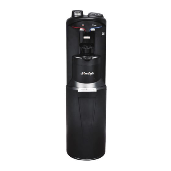
Storm Café The Storm Café water dispenser with coffee brewer is the latest model in the Storm family of coolers. The Café combines the convenience of the original Storm bottom load cooler with a single serve coffee cup type brewer. This generation of the Storm has an upgraded fascia with lighting over each faucet handle. -
Page 5: Dimensional Drawing
Dimensional Drawing Dimensions are shown in Inches (mm) 5.273 (133.93) 7.904 (200.76) 45.172 (1147.37) 12.598 13.386 (319.99) (340) -
Page 7: Section 2: Parts Listing And Exploded Views
Parts Listing DESCRIPTION ABFM2KHK1CF Tube Guide, Hot PLC-C150176 Handle Assembly (contains hot & cold handles) SUB-G300001 Spring, SS, Faucet FAS-C100104 Pin, Handle 76mm FAS-C100199 Flow Meter ELE-C100489 Tube, Silicone, Flow Meter SIL-C150043 Connector, Water, Female PLC-C150167 Valve, One Way POU-C100100 Cover, Pump PLC-C150174 10. -
Page 8: Exploded Views
Exploded View 32, 33 34, 35 47, 48 39 40 66, 67 52, 53... -
Page 9: Fluid Path Diagram
Fluid Path Diagram Solenoid Steam Valve Brewer Brewer Head Housing SmartFlo Pinch Valve Flow Connector Brewer Meter Pinch Tank Water Coffee Pod Valve Cold Pump Switch One-Way Reservoir Bottle Hot Water Valve Coffee Dispense Cold Water Dispense Air Pump Dispense Electrical Diagram Hot Switch White... -
Page 10: Section 3: Water Bottle Installation And Replacement
Water Bottle Installation and Replacement Open Dispenser door (Fig.1). Slide door upward to access bottle area. Fig. 1 Place fresh bottle outside of the cabinet. Clean the outside of new bottle with a cloth (Fig. 2). Fig. 2 Remove label/seal from the bottle cap (if applicable) and insert spike cap through the bottle cap (do not remove bottle cap) and press down to secure (Fig. - Page 11 Remove the red protective cap from the blue tube of the SmartFlo and install onto the bottle adapter assembly (Fig. 7). Fig. 7 Slide bottle into cabinet (Fig. 8) and close the door. Push down to close. Fig. 8 Depress the cold lever to fill the cold water tank (Fig. 9). When water begins to flow in a steady stream from the cold faucet, the tank has been filled (approximately 1 minute although it may be less time).
- Page 12 Changing the Water Bottle A blinking blue light above the cold water lever and a blinking “Replace Bottle” on the brew selection panel will alert you when your water bottle is getting low. Water may be dispensed normally until empty (no water flows from the water outlets when lev- ers are depressed).
- Page 13 Install Spike Cap through the bottle cap (do not remove bottle cap) and press down to secure (Fig. 16 & 17) Fig. 16 Fig. 17 Insert the Bottle adaptor assembly through Spike cap until tube hits bottom of the bottle (Fig. 18 & 19). Fig.
-
Page 14: Section 4: Replacement Of Smartflo™ System
Replacing the SmartFlo™ Notice: The information and/or procedures presented in the following demonstration(s) should be performed by a trained Water Cooler Service Technician only. Never attempt to service or repair a water cooler while it is plugged into any power supply. Prior to any service or repair of the water cooler, ensure that the water has been completely drained from the system. - Page 15 Using the top cover key (Fig. 6), insert into the two holes (on the front, approximately 2 inches above and to the right of hot water safety button), push key inward to open top cover (Fig. 7 & 8). Fig. 6 Fig.
- Page 16 Close and latch the locking arm (Fig. 20). Fig. 20 Install the hose connecter to bottle adapter (Fig. 21). Put the water bottle into the bottom of the cooler. Fig. 21 Close the top cover and lower the door to close. Plug the cooler into the electrical outlet. Pull the cold faucet lever until a steady stream of water comes out.
-
Page 17: Section 5: Electrical Diagnosis And Replacement
Cold Control Replacement Notice: The information and/or procedures presented in the following demonstration(s) should be performed by a trained Water Cooler Service Technician only. Never attempt to service or repair a water cooler while it is plugged into any power supply. Prior to any service or repair of the water cooler, ensure that the water has been completely drained from the system. - Page 18 Cut the small plastic zip tie holding the cold control sensor bulb to the evaporator insulation (Fig. 8). Fig. 8 Pull the sensor tube out from the evaporator insulation to remove (Fig. 9). Note: If required, install the Sensor tube cover onto the replacement cold control.
-
Page 19: Cold Control Adjustment
Cold Control Adjustment Note: The Cold Control can be adjusted without the removal of any panel. The adjustment screw is on the top rear (when viewed from the rear, see Fig. 1). To make the water colder, rotate the screw in the clockwise direction approximately 1 hour position. Allow the cooler to stabilize for 2-3 hours to ensure proper temperature of the cold water. -
Page 20: Hot Thermostat/Limiter Replacement
Thermostat and/or Limiter Replacement Notice: The information and/or procedures presented in the following demonstration(s) should be performed by a trained Water Cooler Service Technician only. Never attempt to service or repair a water cooler while it is plugged into any power supply. Prior to any service or repair of the water cooler, ensure that the water has been completely drained from the system. -
Page 21: Hot Tank Replacement
Hot Tank Replacement Notice: The information and/or procedures presented in the following demonstration(s) should be performed by a trained Water Cooler Service Technician only. Never attempt to service or repair a water cooler while it is plugged into any power supply. Prior to any service or repair of the water cooler, ensure that the water has been completely drained from the system. - Page 22 Remove the wires connected to the thermostat and limiter (Fig. 13). Remove the ground wire from the hot tank. Locate the two terminals at the bottom of hot tank and disconnect the wires from the Hot Tank Element. Disconnect the NTC sensor wires (coming from top of hot tank) from the circuit board (Fig.
- Page 23 Plug the cooler back into power outlet. Push hot safety button and press the hot water faucet lever until water comes out (Fig. 19). CAUTION: To prevent damaging the hot tank, do not turn ON if the hot tank is empty. Fig.
-
Page 24: Compressor Relay/Overload Replacement
Overload and/or Relay Replacement Notice: The information and/or procedures presented in the following demonstration(s) should be performed by a trained Water Cooler Service Technician only. Never attempt to service or repair a water cooler while it is plugged into any power supply. Prior to any service or repair of the water cooler, ensure that the water has been completely drained from the system. - Page 25 Reinstall the cover (Fig. 12) and secure with the metal clip (Fig. 13). Note: use caution not to damage wires. Fig. 12 Fig. 13...
-
Page 26: Section 6: Cleaning & Sanitization
Cleaning and Sanitization Notice: The information and/or procedures presented in the following demonstration(s) should be performed by a trained Water Cooler Service Technician only. Never attempt to service or repair a water cooler while it is plugged into any power supply. Prior to any service or repair of the water cooler, ensure that the water has been completely drained from the system. - Page 27 Using the top cover key (Fig. 6), insert into the two holes (on the front, approximately 2 inches above and to the right of hot water safety button). Push key inward to open top cover (Fig. 7 and 8). Fig. 6 Fig.
- Page 28 It is recommended that the hot tank be descaled periodically (depending upon water quality and usage). Only the use of food- safe descaling agents, compatible with 304 grade stainless steel, is recommended. The use of the descaling agents must be in accordance with the manufacturer’s safety instructions and recommendations and performed by properly trained personnel.
- Page 29 13. Install a new SmartFlo™ Water Cartridge. Install the connector and corrugated tube into the inlet through cooler to bottom (Fig. 30 & 31). Insert the reservoir into evaporator (Fig. 32). Ensure the SmartFlo™ is installed properly. Turn the two knobs to lock the SmartFlo™...
- Page 30 16. Install the hose connecter to adapter (Fig. 40). Put the water bottle into the bottom of the cooler. Fig. 40 17. Close the top cover and lower the door to close. Clean the drip tray assembly and install it back onto cooler. Plug the cooler into the electrical outlet.
-
Page 31: Monthly Cleaning And Sanitizing Of The Brewer
Monthly Cleaning With Detergent Pod (Not Supplied) With the coffee machine turned on and at temperature, open the coffee pod holder (Fig. 18), insert the detergent pod and close the lid (Fig. 19 ). Fig. 18 Fig. 19 Place a glass or similar container under the water outlet (Fig 20). Select the twelve cup option and press the “Brew” but- ton to start the cleaning cycle (Fig 21). -
Page 32: Clearing The Inlet Or Outlet Needle
Cleaning the Inlet or Outlet Needle Locate a metal paper clip and bend it so that there is a long straight section (Fig. 1). Fig. 1 To clean the inlet needle, open the cooler top. Open the pod holder lid and remove the brown cup holder. Locate and turn both red twist locks (Fig. - Page 33 While holding the pod holder assembly in one hand, locate the opening in the exit needle (Fig. 9) and insert the straightened paper clip into the hole and gently spin or rock the paperclip to remove any grounds which might be sticking to the needle (Fig 9).
-
Page 34: Section 7: Displaying And Clearing Fault Codes
Displaying and Clearing the Fault Codes To Display the Fault Code Fig. 1 Turn off the Hot Tank Power Switch (Fig. 1) Press and hold the “8 ounce” and “10 ounce” buttons for five seconds (Fig. 2 & 3). Fig. 2 Fig. -
Page 35: Section 8: Purging Water From System
Purging the Brew Head of Water (if equipped) Turn off the Hot Tank Power Switch (Fig. 1), but leave the unit plugged into the electrical outlet. Fig. 1 CAUTION: WATER IN HOT TANK IS VERY HOT AND CAN CAUSE SEVERE BURNS. ALLOW SUFFICIENT TIME FOR THE HOT WATER TO COOL BEFORE DRAINING (1-2 HOURS). -
Page 36: Section 9: Troubleshooting
If water present only at base of unit (not dripping from above), replace the water bottle. If water leaking from above the bottle (or not bottle related), unplug Dispenser, remove bottle and contact your water delivery service or Crystal Mountain. Ensure that the drip tray is not full and overflowing. - Page 37 Crystal Mountain Products Inc 1000H Taylor Station Rd Gahanna OH 43230 Copyright ©2020 Crystal Mountain Products Inc Manufactured under U.S. Patent No. 10,781,093 and other patents pending Form 2007001 Rev 03.21...
Need help?
Do you have a question about the Storm Café and is the answer not in the manual?
Questions and answers