
Related Manuals for Iron Bow MEDVIEW-V-10X-A01


Summary of Contents for Iron Bow MEDVIEW-V-10X-A01
- Page 1 ™ Iron Bow MedView Installation and User Guide For use with MedView Model Number: MEDVIEW-V-10X-A01 Document Version 2.0 Document # DOC-UG-MEDVIEW-V-10X-A Version 2.0 3/03/2021 Copyright 2021 Iron Bow Technologies...
- Page 2 Copyright © 2021 Iron Bow Technologies All Rights Reserved. Specifications subject to change without notice. For general inquiries, contact: Iron Bow Healthcare Solutions 2303 Dulles Station Boulevard, Suite 400 Herndon, VA 20171 Toll: 800.338.8866 Tel: 703.279.3000 www.ironbowhealthcare.com For support, contact: Iron Bow Client Service Center Toll: 833.476.6269 (833.IRONBOW)
- Page 3 If the apparatus has been exposed to rain or moisture If the apparatus has been subjected to excessive shock by being dropped, or the cabinet has been damaged If the apparatus fails to operate in accordance with the operating instructions. Copyright 2021 Iron Bow Technologies...
- Page 4 This document provides general guidelines only. Direction for proper cleaning and infection control is the responsibility of local authority and hospital administration. Iron Bow is not responsible for improper cleaning or disinfection in any and all circumstances. Copyright 2021 Iron Bow Technologies...
- Page 5 In addition, AC power strips or extension cables should not be used with this system. Ambient Temperature Guidelines Operating temperature: 5°C –35°C (ambient temperature) Operating humidity: 20%–80% (RH) Non-operating temperature: -20°C –60°C Non-operating humidity (non-condensing): 10%–90% Copyright 2021 Iron Bow Technologies...
-
Page 6: Table Of Contents
Mandatory MedView Settings ................Error! Bookmark not defined. Enable/Disable Auto Answer ................. Error! Bookmark not defined. Change Sleep Settings .................... Error! Bookmark not defined. Add Contacts ......................Error! Bookmark not defined. Appendix #1: Specifications ........................20 Specifications ..............................21 Copyright 2021 Iron Bow Technologies... -
Page 7: Table Of Figures
Figure 8 - Assemble MedView on a post mount ....................15 Figure 9 - Connection Ports ..........................15 Figure 10 - WiFi antenna assembly ........................16 Figure 11 - HDMI switch example ........................17 Figure 13 - MedView Dimensions ........................20 Copyright 2021 Iron Bow Technologies... -
Page 8: Introduction
This user guide covers the assembly and installation of the Iron Bow MedView, part # MEDVIEW-V-10X-B01. For Administration and Configuration of the Iron Bow MedView, refer to the VidyoRoom™... -
Page 9: System Description
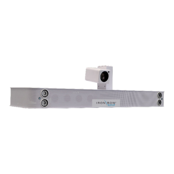
System Description The primary components of the Iron Bow MedView are shown below: Figure 2 - MedView Major System Components 1. System Camera 6. Microphone Input 2. Infrared Illuminators 7. USB 3 Ports 3. System Audio Bar 8. Ethernet Network 4. -
Page 10: System Installation
The MedView is designed to be mounted on an existing wall arm that is already supporting a monitor using the monitor VESA mounting hole pattern. Iron Bow sells adapter plates to allow for mating the MedView with the VESA mount. Each mount uses the smaller mounts as base components. -
Page 11: Assembly On A Monitor
If it is necessary to install the MedView so it it not parallel to the monitor face, the ¼-20 screw can be used alone and will allow the unit to be angled as needed. Figure 3 - Assemble MedView to Bracket Copyright 2021 Iron Bow Technologies... -
Page 12: Attach The Medview/Medview-Brkt100-A01 Bracket Assembly To The Monitor
Use the (4) M4x25 Phillips pan head screws to secure the bracket to the monitor. b. If no spacers are used, use the (4) M4x18 Phillips pan head screws to secure the bracket to the monitor. Figure 4 - Assemble MedView to Monitor Copyright 2021 Iron Bow Technologies... -
Page 13: Assemble Medview-Brkt200-A01 To A Monitor
5. Secure the bracket assembly to the monitor using M6 or M8 pan head screws. With spacers, use 25mm long screws, and 16mm without spacers. Figure 5 - Add bracket for 200 x 200 Mount Copyright 2021 Iron Bow Technologies... -
Page 14: Assemble Medview-Brkt400-A01 To A Monitor
8. Secure the bracket assembly to the monitor using M6 or M8 pan head screws. With spacers, use 25mm long screws, and Figure 6 - Counterbore hole detail view 16mm without spacers. Figure 7 - Add bracket for 400 x 400 mount Copyright 2021 Iron Bow Technologies... -
Page 15: Assembly On A Security Camera Mount (Without An Attached Monitor)
8. DisplayPort 1 – install DisplayPort to HDMI cable (provided) to monitor or to a signal priority device (ex. ACC-HDMISWITCH-A01) 9. DisplayPort 2 – not used 10. (4) USB 3.0 ports – use for special equipment a. Keyboard/mouse for system setup b. Spider Audio option (ACC-AUDIO-SPDR-A01) Copyright 2021 Iron Bow Technologies... -
Page 16: Wi-Fi Network
Installing the Wi-Fi Antennas 1. Attach the two Wi-Fi antenna supplied with the unit to the MedView chassis as shown. They should be easily threaded onto the exposed connector. Do not overtighten. Figure 10 - WiFi antenna assembly Copyright 2021 Iron Bow Technologies... -
Page 17: Connecting To The Monitor
See the ACC-HDMISWITCH-A01 priority switch below for an example. Non-HDMI monitor inputs will likely require upscalers or converters to transition from one technology to another. See the Iron Bow Application engineer for assistance. Figure 11 - HDMI switch example Copyright 2021 Iron Bow Technologies... -
Page 18: Getting Started
Wi-Fi with external antenna, or using the 10/100/1G Ethernet port. To connect the MedView to a Wi-Fi network, please refer to VidyoRoom™ and VidyoPanorama™ 600 Administrator Guide: VidyoRoom and VidyoPanorama 600 Administrator Guides and VidyoRoom SE Deployment Guides Copyright 2021 Iron Bow Technologies... -
Page 19: Control Functions
Users can purchase remote controls for the MedView that allow for in-room call and volume control For more information on the MedView remote controls, refer to the Iron Bow Remote Control User Guide available at https://ironbowhealthcare.com. -
Page 20: Appendix #1: Specifications
Appendix #1: Specifications The following diagram is not to scale & is provided for dimensional information only . Figure 12 - MedView Dimensions Copyright 2021 Iron Bow Technologies... -
Page 21: Specifications
N/A – uses the existing in-room infotainment display Control Customer provided keyboard (USB) Optional Iron Bow ACC-V-REMOTE-A01 tethered remote control (USB) Optional Iron Bow ACC-V-VOLCTRL-A01 tethered remote volume control (USB) Video Inputs 1x - Main Camera (Integrated) Video Output 2x DisplayPort (#1-Dedicated to Display; #2-not used) - Page 22 Page Intentionally left blank Copyright 2021 Iron Bow Technologies...
- Page 23 This Page Intentionally Left Blank - Copyright 2021 Iron Bow Technologies...
- Page 24 2303 Dulles Station Boulevard, Suite 400 Herndon, VA 20171 Toll: 800.338.8866 Tel: 703.279.3000 www.ironbowhealthcare.com Copyright 2021 Iron Bow Technologies...
Need help?
Do you have a question about the MEDVIEW-V-10X-A01 and is the answer not in the manual?
Questions and answers