Advertisement
STM23C/24C Quick Setup Guide
Requirements
To begin, make sure you have the following equipment:
▪
A small flat blade screwdriver for tightening the power connector (included).
▪
A personal computer running Microsoft Windows XP, Vista, 7, 8, or 10 (32 or 64 bits).
▪
ST Configurator™ software (available at www.applied-motion.com).
▪
CANopen programming cable (to host) (included)
▪
CANopen daisy-chain cable (motor to motor)
▪
RS-232 cable for connecting to a PC so you can configure the settings on your motor using ST Configurator™ (included)
▪
For more detailed information, please download and read the STM23 Hardware Manual or STM24
Hardware Manual, available at www.applied-motion.com/support/manuals.
Step 1 - Wiring
▪
Wire the drive to the DC power source.
Note: Do not apply power until Step 3.
The STM23C and STM24C accept DC supply volt-
ages between 12 and 70 volts DC. If using an ex-
ternal fuse we recommend the following:
STM23C: 4 amp fast acting
STM24C: 5 amp fast acting
See the STM23 and STM24 Hardware Manuals for more
information about power supply and fuse selection.
▪
Connect I/O as required by your application.
Cable part number 3004-318 can be used for this purpose
▪
Connect to the CAN network.
Cable part number 3004-310 connects one mo-
tor to the next (daisy-chain) in the CAN network
▪
Set Bit Rate and Node ID
Bit rate is set using a ten-position rotary
switch. See Bit Rate table for settings.
Node ID is set using a combination of sixteen-position
rotary switch and a software setting in ST Configura-
tor. The sixteen-position rotary switch sets the lower
four bits of the Node ID. ST Configurator sets the up-
per three bits of the Node ID. Valid ranges for the Node
ID are 0x01 through 0x7F. Node ID 0x00 is reserved
in accordance with the CiA 301 specification.
Note: Node ID and Bit Rate are captured only af-
ter a power cycle or after a network reset command
has been sent. Changing the switches while the
drive is powered on will NOT change the Node ID un-
til one of these conditions has also been met.
▪
Connect the RS-232 programming cable (in-
cluded) between the motor and the PC
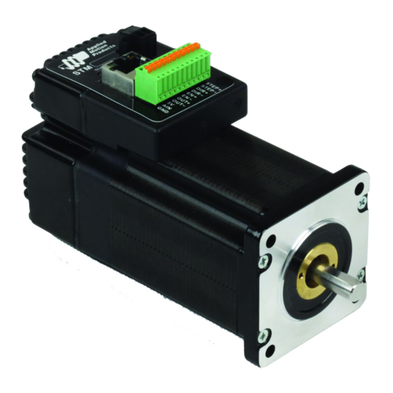
POWER CONNECTIONS
STATUS LEDs
NODE ID
CANopen/RS-232
Daisy Chain Cable
3004-310
STM #2
STM#1
Switch Setting
0
1
2
3
4
5
6
7
8
9
Bit Rate Table
BIT RATE
I/O CONNECTIONS
CANopen/RS-232
Host Device
Host Cable
3004-313
UP TO
127
AXES
Resultant Bit Rate
1 Mbps
800kbps
500 kbps
250 kbps
125 kbps
50 kbps
20 kbps
12.5 kbps
n/a
n/a
920-0043 C
Advertisement
Table of Contents

Related Manuals for Applied Motion Products STM23C


Summary of Contents for Applied Motion Products STM23C
- Page 1 I/O CONNECTIONS Note: Do not apply power until Step 3. STATUS LEDs The STM23C and STM24C accept DC supply volt- ages between 12 and 70 volts DC. If using an ex- ternal fuse we recommend the following: STM23C: 4 amp fast acting...
- Page 2 STM23C or STM24C and power supply are correctly wired and configured. When configuration is complete, exit the ST Configurator™. The drive will automatically switch to CANopen Mode. If you have any questions or comments, please call Applied Motion Products Customer Support: (800) 525-1609, or visit us online at www.applied-motion.com.
Need help?
Do you have a question about the STM23C and is the answer not in the manual?
Questions and answers