Table of Contents
Advertisement
Quick Links
®
SYSTIMAX
Solutions
SYSTIMAX
General
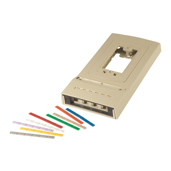
The SYSTIMAX
M10MMFP multimedia faceplate brings copper and fiber to a common faceplate, in an existing
or new installation. It works with up to six port single-gang modular faceplates, and may be configured with ST
SC, or LC couplers, in various densities. Adapter plates are provided for use with two SC Duplex, four LC
Duplex, or the high density modular couplers available in ST, SC, and LC configurations.
The multimedia faceplate enables independent access to either copper or fiber terminations on the wall side of
the unit. It may be installed in existing copper networks without disconnecting or removing the modular jacks
form the faceplate. The faceplate base has a convenient pivot and snap mount that permits easy access to the
copper terminations from the back of the faceplate. The snap-on cover provides labeling features such as a
paper label for circuit identification, and plastic icon strip recess, compatible with the SYSTIMAX multi-color
plastic icon strips.
Ordering information is listed below:
Material ID
Part No.
108502287
M10MMFP-003
108502295
M10MMFP-215
108502303
M10MMFP-246
108502329
M10MMFP-262
108502337
M10MMFP-270
www.commscope.com
M10MMFP Multimedia Faceplate Instructions
Description
Multimedia faceplate – Black
Multimedia faceplate – Creme
Multimedia faceplate – Ivory
Multimedia faceplate – White
Multimedia faceplate – Gray
M10MMFP Multimedia Faceplate
© 2013 CommScope, Inc. All rights reserved
Instruction Sheet 848380986
Issue 6, June 2013
Page 1 of 11
®
Advertisement
Table of Contents

Related Manuals for CommScope SYSTIMAX M10MMFP


Summary of Contents for CommScope SYSTIMAX M10MMFP
- Page 1 Multimedia faceplate – Black 108502295 M10MMFP-215 Multimedia faceplate – Creme 108502303 M10MMFP-246 Multimedia faceplate – Ivory 108502329 M10MMFP-262 Multimedia faceplate – White 108502337 M10MMFP-270 Multimedia faceplate – Gray M10MMFP Multimedia Faceplate © 2013 CommScope, Inc. All rights reserved Page 1 of 11...
-
Page 2: How To Contact Us
1-800-344-0223. Outside the United States, contact your local account representative or Authorized Business Partner. Within the United States, report any missing/damaged parts or any other issues to CommScope Customer Claims at 1-866-539-2795. Outside the United States, contact your local account representative or Authorized Business Partner. Tools Required ... -
Page 3: Important Safety Instructions
848380986 Issue 6, June 2013 Separately Orderable Parts Material ID Part No. Quantity Description Used With 108547282 Labels, in poly bag M10MMFP 107118903 C6061A-4 Coupling, SC, mm, duplex, Beige, SC adapter plate metal sleeve 107087967 C6070A-4 SC adapter plate... -
Page 4: Base Features
848380986 www.commscope.com Instruction Sheet Base Features The base attaches to a wall outlet box or to a flat surface using the alternate mounting holes. It provides slack storage for the fiber, four cable attachment points for rear entrance cables, two cable attachment points for side entrance cable, mounting rails for the coupling adapter plates, mounting features for the faceplate base, cover attachment features, and side cutouts for side entrance of cable. -
Page 5: New Installation
848380986 Issue 6, June 2013 New Installation Step 1 – Install Base (Copper and Fiber Installation) For Fiber Cable 1. Insert fiber cable(s) through opening in base, ensuring at least 3 feet (0.9m) of fiber cable extends through base. - Page 6 848380986 www.commscope.com Instruction Sheet Step 2a – Fiber Cable Installation 1. Anchor fiber cable to one of the tie-down points around the perimeter of the base opening, using a small cable tie (provided). Ensure that the jacket extends 1/4- to 1/2-inch (6 to 13mm) beyond the cable tie to protect the buffered fibers from sharp bends.
- Page 7 848380986 Issue 6, June 2013 Step 2b – Copper Cable Installation 1. Strip the copper cordage per local practices for attachment to modular outlets and terminate to the modular jacks. 2. Feed the terminated cordage and jacks through the back of the faceplate base and snap the individual modules into the faceplate.
- Page 8 848380986 www.commscope.com Instruction Sheet Step 2 – Install Faceplate Base and Route New Fiber Cables 1. Strip 3 feet (1 meter) of jacket from the fiber cable. 2. Attach fiber cable to base using a cable tie at one of the cable tie down points around the inside of the slack drum.
- Page 9 848380986 Issue 6, June 2013 6. Fit hooks on bottom of faceplate base into catches on base. Ensure that the slack fibers are clear of the faceplate base catches and latch before engaging. Pivot faceplate base up and press the top of the faceplate base in until the latch at the top engages with the base engage.
- Page 10 848380986 www.commscope.com Instruction Sheet Step 3 – Secure Faceplate and Install Cover 1. Attach the faceplate to the faceplate base using two 1/2-inch Phillips Pan-Head PT screws (provided). 2. Attach the cover to the base by engaging the hooks located at the inside top of the cover with the slots located at the top of the base.
- Page 11 848380986 Issue 6, June 2013 Step 4 –Install Optional Protective Metal Cover 1. Position metal cover in front of faceplate unit as shown above. 2. Slide cover over faceplate, ensuring no cables are crimped under the edges. 3. Mark mounting hole locations per the three mounting tabs furnished on the cover, then remove cover.
Need help?
Do you have a question about the SYSTIMAX M10MMFP and is the answer not in the manual?
Questions and answers