Advertisement
Quick Links
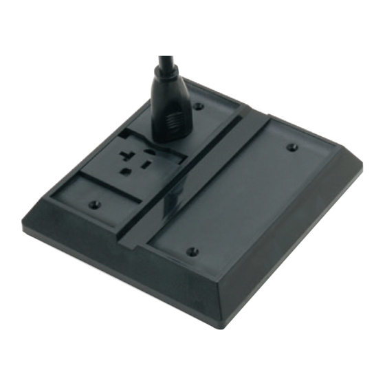
Single Duplex
DCR Kit
Attaching
Hardware
Top Shield Bonding
Clip (Qty: 4)
Dual Duplex
DCR Kit
Combination DCR Kit
(Duplex Receptacle
and Blank)
PART NUMBER
D
15 A
20 A
(Canadian Version)
553947--[ ]
554128--[ ]
554192--[ ]
554321--[ ]
554142--[ ]
554319--[ ]
Dash Number Indicates Color: - - 1 is Black, - - 3 is Gray
D
Figure 1
All dimensions on this document are in metric
NOTE
units [with U.S. customary units in brackets].
i
Figures are not drawn to scale.
AMP NETCONNECT logo is a trademark of CommScope.
AMP NETCONNECT® Undercarpet Power
Cabling System 3- Conductor Direct
Connecting Receptacle (DCR) Kits
Cover
Duplex Receptacle
Assembly
Mounting
Plate
DESCRIPTION
Single Duplex
Dual Duplex
Combination
(Duplex Receptacle and Blank)
© 2016 CommScope, Inc.
All Rights Reserved
1. INTRODUCTION
This instruction sheet covers installation and removal
of the DCR kits shown in Figure 1. The DCR kits
accept 3--conductor undercarpet cable size 10 or 12
AWG. The blank side of the combination DCR kit
accepts Modular Jack Kits 558054--1 (Category 5e)
and 1933377--1 (Category 6) available separately.
Modular Jack Bracket Assembly 1499543--1 (used to
mount the jack to the mounting plate) is also available
separately.
Undercarpet Hold--Down Tape 553481--1 is availabe
for securing the cable to the floor.
Reasons for reissue of this instruction sheet are
provided in Section 5, REVISION SUMMARY.
To obtain information on AMP NETCONNECT®
products, contact your local CommScope® account
representative, PartnerPRO™ Network Partner or
visit our website at www.commscope.com.
2. DESCRIPTION
Each DCR kit consists of one or two mounting plates,
one or two duplex receptacle assemblies, a cover, four
top shield bonding clips, and attaching hardware.
3. INSTALLATION PROCEDURE
TO AVOID PERSONAL INJURY, disconnect the
DANGER
electrical power before beginning work on any
circuit.
3.1. Single or Dual Duplex DCR Kit
1. Center the mounting plate on a chalk line using
the center indicator marks. Use the mounting plate
as a template to mark the mounting hole locations.
Prepare the surface (drill holes for the customer--
supplied mounting hardware and vacuum debris).
See Figure 2.
2. Lay the 3--conductor undercarpet power cable,
bottom vinyl shield first, onto the floor.
For slab--on--grade installation, install Floor
Preparation 554123--[ ] according to 408--3154
prior to laying the cable.
To avoid damage from from moisture, chemical
CAUTION
reaction, or abrasion, the floor preparation must
!
be installed prior to laying the cable for
slab- - on- - grade installation.
Check to make sure that the four top shield
NOTE
bonding clips are on the mounting plate.
i
Top Shield Bonding Clip 554178- - 1 (50 per box)
is also available separately.
This product is covered by one or more U.S.
patents or their foreign equivalents. For patents, see
www.commscope.com/ProductPatent/ProductPatent.aspx
Instruction Sheet
408- - 3129
Dec. 2016, Rev E
1 of 4
Advertisement

Subscribe to Our Youtube Channel
Related Manuals for CommScope AMP NETCONNECT 553947 Series


Summary of Contents for CommScope AMP NETCONNECT 553947 Series
- Page 1 Top Shield Bonding Clip 554178- - 1 (50 per box) is also available separately. AMP NETCONNECT logo is a trademark of CommScope. © 2016 CommScope, Inc. 1 of 4 This product is covered by one or more U.S.
- Page 2 408- 3129 Undercarpet Power Cabling System 3- Conductor DCR Kits Center Indicator assembly will enter the blank holes in the Marks mounting plate. See Figure 5. 6. For dead--end application: a. Cut the cable square about 6.4 mm [.25 in.] from the end of the mounting plate.
- Page 3 408- 3129 Undercarpet Power Cabling System 3- Conductor DCR Kits b. Slide the bottom vinyl shield under the 3.2. Combination DCR Kit mounting plate and fold the top vinyl shield 1. Install the mounting plate and receptacle back. Observe polarity and insert the end of the assembly as described in Paragraph 3.1.
- Page 4 5. REVISION SUMMARY Revisions to this instruction sheet include: 1. Remove the attaching hardware securing the S Rebranded to CommScope. cover to the mounting plate, then remove the cover. Refer to Figure 10. 2. Remove the two outer screws of the receptacle assembly, open the cover, then remove the center screw from the receptacle assembly.
Need help?
Do you have a question about the AMP NETCONNECT 553947 Series and is the answer not in the manual?
Questions and answers