
Related Manuals for JVC TM-A101G/E


Summary of Contents for JVC TM-A101G/E
-
Page 1: Table Of Contents
TM-A101G SERVICE MANUAL COLOUR VIDEO MONITOR BASIC CHASSIS TM-A101G S2M1 TM-A101G CONTENTS SPECIFICATIONS OPERATING INSTRUCTIONS (APPENDIX) SAFETY PRECAUTIONS FEATURES SPECIFIC SERVICE INSTRUCTIONS SERVICE ADJUSTMENTS STANDARD CIRCUIT DIAGRAM (APPENDIX) PARTS LIST No.51921 COPYRIGHT © 2001 VICTOR COMPANY OF JAPAN, LTD. Dec. 2001... -
Page 2: Specifications
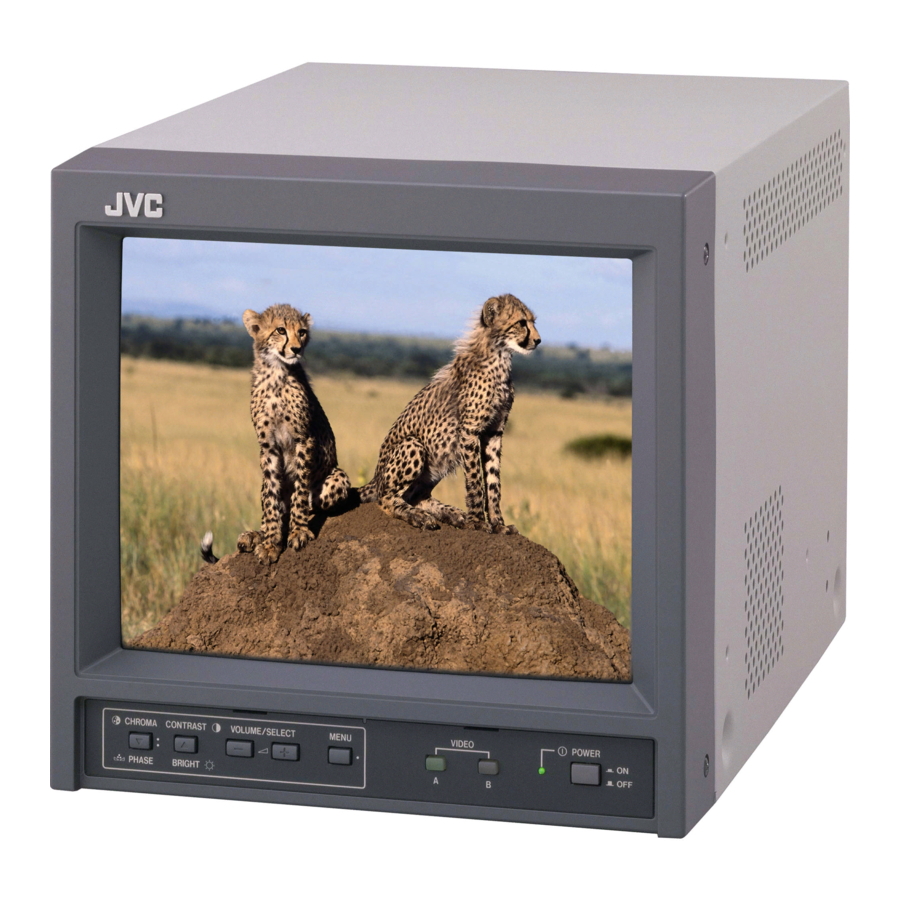
TM-A101G SPECIFICATIONS Item Content Dimension (W H D) 222mm 220mm 316.3mm / 8-3/4” 8-11/16” 12-1/2” Mass 6.8kg / 15.0lbs Colour system PAL / NTSC 3.58 25cm / 9-7/8” measured diagonally Flat-square type Picture tube 90 deflection, in-line gun trio–dot type (phosphor dot-trio pitch 0.5 mm) 175mm 137mm (W H) / 222mm (Diagonal) Effective screen size 6-15/16”... -
Page 3: Safety Precautions
TM-A101G SAFETY PRECAUTIONS 1. The design of this product contains special hardware, many 10. Isolation Check circuits and components specially for safety purposes. For (Safety for Electrical Shock Hazard) continued protection, no changes should be made to the After re-assembling the product, always perform an isolation original design unless authorized in writing by the manufacturer. - Page 4 TM-A101G SAFETY PRECAUTIONS 1. The design of this product contains special hardware and many 4. The leads in the products are routed and dressed with ties, clamps, circuits and components specially for safety purposes. For tubing’s, barriers and the like to be separated from live parts, high continued protection, no changes should be made to the original temperature parts, moving parts and / or sharp edges for the design unless authorized in writing by the manufacturer.
-
Page 5: Features
TM-A101G FEATURES MAIN MICOM (IC731) PIN ARRANGEMENT PORT NUMBER PIN NAME PORT NUMBER PIN NAME H SYNC V SYNC OSC2 OSC1 V CENTER RESET A VOLUME CUTOFF KEY IN3 COMB SWITCH KEY IN2 POWER ON/OFF KEY IN1 AUDIO MUTE SDA2 ASP REM SDA1 SCL2... -
Page 6: Specific Service Instructions
TM-A101G SPECIFIC SERVICE INSTRUCTIONS DISASSEMBLY PROCEDURE CAUTION CHECKING THE PW BOARD To check the PW board from back side. Even with the power switch off, some parts of this unit are live. Be (1) Remove the chassis base and the other PW boards. sure to disconnect the power plug from the AC outlet before (2) Erect the chassis base vertically so that you can easily check the disassembly and reassembly. - Page 7 TM-A101G FRONT PANEL ASS’Y TOP COVER CRT SOCKET PWB (CLAW) SPEAKER Fig.3 CHASSIS MAIN PWB BASE FRONT CONTROL SIGNAL PWB Block TERMINAL BRACKET REAR PANEL CHASSIS BASE MAIN PWB (POWER&DEF. Bolck) BOTTOM COVER POWER CORD Fig.2 No.51921...
- Page 8 TM-A101G REPLACEMENT OF MEMORY IC 1. MEMORY IC This model uses memory IC. In the memory IC, memorized data for correctly operating for the video-chroma, deflection and the other control circuits. SET-UP MENU When replacing memory IC, be sure to use the IC written with <...
- Page 9 TM-A101G INITIAL SETTING OF THE SET-UP MENU TABLE Setting item Setting content / Range Initial setting value H. POSITION CUTOFF (R / G / B) WHITE BALANCE DRIVE (R / B) CONTROL LOCK STATUS DISPLAY INPUT REMOTE ASPECT REMOTE INITIAL SETTING OF THE MENU SCREEN TABLE Setting item Setting content / Range Initial setting value...
- Page 10 TM-A101G BLOCK SELECT ADJUSTMENT ITEM DEFLECTION BLOCK SIGNAL BLOCK SERVICE ITEM CONTENTS SERVICE ITEM CONTENTS BRIGHT HORIZONTAL POSITION CONTRAST VERTICAL SIZE CHROMA(PAL) VERTICAL SIDE PIN CORRECTION CHROMA(NTSC) VERTICAL CENTER CHROMA(SECAM) VERTICAL LINEARITY PHASE(NTSC) In addition to the ones listed above, the following DEFLECTION BLOCK are BRIGHT(16:9) also available.
-
Page 11: Service Adjustments
TM-A101G SERVICE ADJUSTMENTS BEFORE STARTING FOCUS AND SCREEN SERVICE ADJUSTMENT ADJUSTMENT HOLES The FOCUS and SCREEN adjustment holes are on the side 1. Confirm the proper AC power voltage is being supplied. panel. 2. Supply power to the set and measuring instruments and allow to warm up for at least 30 minutes. - Page 12 TM-A101G ADJUSTMENT LOCATIONS MAIN PWB POWER VIDEO B VIDEO A FRONT IND./SW IND./SW IND./SW (FRONT CONTROL Block) MENU +(UP) -(DOWN) CONTRAST CHROM /BRIGHT A/PHASE VOLUME /SELECT POWER SW S901 MAIN PWB FRONT (POWER & DEF. Block) FUSE F901 SIGNAL PWB UPPER : FOCUS VR LOWER...
- Page 13 TM-A101G UPPER CRT SOCKET PWB (SOLDER SIDE) TP-47G CRT EARTH WIRE TO MAIN PWB (BRAIDED ASS'Y) TP-E TP-47B UPPER SIGNAL PWB VIDEO A VIDEO B AUDIO A AUDIO B REMOTE (INPUT/ASPECT) SHIELD CASE SPEAKER CN001 No.51921...
- Page 14 TM-A101G BASIC OPERATION OF SERVICE MENU 1. SERVICE MENU ITEMS With the SERVICE MENU, various settings can be made, and they are broadly classified in the following items of adjustments. It is no requirement for adjustment the portion of the DEFLECTION BLOCK and CONTROL BLOCK. This block adjusts the data of the various signal SIGNAL BLOCK circuit controls.
- Page 15 TM-A101G (2) OPERATION OF <BLOCK SELECT> SCREEN SERVICE MENU While the SERVICE MENU <BLOCK SELECT> screen is displaying, in accordance with the key control display (Function Display) at the lower side < BLOCK SELECT > of the screen, be able to operate the various items (Fig. 5). SIGNAL BLOCK WHITE BALANCE BLOCK DEFLECTION BLOCK...
- Page 16 TM-A101G HOW TO OPERATE EACH SERVICE MENU ITEMS SIGNAL BLOCK SIGNAL BLOCK In the <BLOCK SELECT> screen , press the CHROMA/PHASE key. Then SIGNAL BLOCK adjustment mode screen is displayed (Fig. 7). The original front key function replaced with the different function displayed at the lower side of the screen as shown below.
- Page 17 TM-A101G [ WHITE BALANCE Adjustment : METHOD 1 ] CUTOFF ADJUSTMENT SCREEN Accordance with the screen display, select the each WHITE BALANCE mode following below. CUTOFF adjustment mode (Low light adjustment) In the WHITE BALANCE menu screen, press the CHROMA/PHASE key to enter to the CUTOFF adjustment mode (Fig.
- Page 18 TM-A101G [ WHITE BALANCE Adjustment : METHOD 2 ] WHITE BALANCE W01 mode SERVICE MENU has the other method for adjusting the WHITE BALANCE about above-mentioned method. In the WHITE BALANCE menu screen, press the VOLUME/SELECT +(UP) key or –(DOWN) key, then enter to the “W01” or “W05” adjustment mode (Fig.
- Page 19 TM-A101G DEFLECTION BLOCK In the <BLOCK SELECT> screen, press the VOLUME/SELECT –(DOWN) key. DEFLECTION BLOCK Then the DEFLECTION BLOCK adjustment screen is displayed (Fig. 14). The original front key function replaced with the other function displayed at the lower side of the screen as shown below. CONTRAST/BRIGHT key is the switch of the screen display.
- Page 20 TM-A101G 4. SERVICE MENU FLOW CHART SERVICE MENU <BLOCK SELECT> SCREEN < BLOCK SELECT > SIGNAL BLOCK WHITE BALANCE BLOCK DEFLECTION BLOCK CONTROL BLOCK SIG W/B DEF EXIT CNTL SIGNAL BLOCK CUTOFF ADJUSTMENT EXIT < S01 > R CUTOFF RGB SERV EXIT WHITE BALANCE BLOCK MENU SCREEN...
- Page 21 TM-A101G INITIAL SETTINGS OF THE SERVICE MENU SIGNAL BLOCK SERVICE Number CONTENTS INITIAL SETTING VALUE BRIGHT CONTRAST CHROMA(PAL) CHROMA(NTSC) CHROMA(SECAM) PHASE(NTSC) BRIGHT(16:9) -001 -015 CONTRAST(16:9) WHITE BALANCE BLOCK SERVICE Number CONTENTS INITIAL SETTING VALUE R CUTOFF G CUTOFF B CUTOFF R DRIVE B DRIVE DEFLECTION BLOCK...
- Page 22 TM-A101G CONTROL BLOCK (This is a fixed value. Don’t adjust it.) SERVICE Number CONTENTS INITIAL SETTING VALUE MODEL UPPER BRIGHT POINT LOWER UPPER CONTRAST POINT LOWER UPPER CHROMA POINT LOWER UPPER PHASE POINT LOWER OSD HORIZONTAL POSITION OSD VERTICAL FREQUENCY (50Hz) OSD VERTICAL FREQUENCY (60Hz) VERTICAL DELAY (NTSC) VERTICAL DELAY (PAL)
- Page 23 TM-A101G SERVICE Number CONTENTS INITIAL SETTING VALUE TRAP Q (PAL) TRAP F0(NTSC) TRAP F0(PAL) TOF SW (NTSC) TOF SW (PAL) TOF Q (NTSC) TOF Q (PAL) TOF F0 (NTSC) TOF F0 (PAL) APA (V. NTSC) APA (V. PAL) APA (V. SECAM) APA (Y/C, B/W) R-Y BLACK OFFSET B-Y BLACK OFFSET...
- Page 24 TM-A101G ADJUSTMENT Adjustment Item Test equipment Test points Adjustment procedure locations TP-91(B1) : SCREEN VR Checking of DC Voltmeter 1. Set power supply voltage to AC230V 5V (TM- [Lower knob : pin) the B1 power A101G ) / AC120V 5V (TM-A101G in FBT] supply 2.
- Page 25 TM-A101G It must be set the composite VIDEO signal input and 4:3 scan mode when adjust the white balance. It is no required to adjust in the under scan screen mode. Adjustment Item Test equipment Test points Adjustment procedure locations White Signal generator SCREEN VR...
- Page 26 TM-A101G Adjustment Item Test equipment Test points Adjustment procedure locations Bright Signal generator S01 (BRIGHT) Under the condition that Low light adjustment adjustment (Sprit colour bar) [SERVICE MENU] has been correctly finished. 1. Input a sprit colour bar signal. 2. Select the SIGNAL BLOCK mode from <BLOCK SELECT>...
- Page 27 TM-A101G Adjustment Item Test equipment Test points Adjustment procedure locations 1. Input a NTSC 3.58 full colour bar signal. NTSC 3.58 Signal generator TP-47B CHROMA (Full colour bar) (NTSC CHROMA) 2. Connect the oscillo-scope probe to TP-47B and TP-E( Saturation [SERVICE MENU] [CRT SOCKET TP-E(...
- Page 28 TM-A101G DEFLECTION CIRCUIT ADJUSTMENT There are 4 modes of DEFLECTION adjustment depending upon the kind of input signals. The adjustments must always be carried out in regular sequence given below. SIGNAL MODE SERVICE NUMBER SETTING VALUE 50Hz (PAL) 60Hz (NTSC) + DA 50Hz (PAL) + DB...
- Page 29 TM-A101G Adjustment Item Test equipment Test points Adjustment procedure locations 9. Input the crosshatch signal. V. Size Signal generator D02 (V.SIZE) Adjustment (Crosshatch pattern) [SERVICE MENU] 10. Select D02 item, and adjust it to the vertical scan size to 95% . 100% Screen Picture...
- Page 30 TM-A101G PURITY / CONVERGENCE ADJUSTMENT PURITY ADJUSTMENT 1. Demagnetize CRT with the demagnetizer. WEDGE DEFLECTION 2. Loosen the retainer screw of the deflection yoke. YOKE 3. Remove the wedges. 4. Input a green raster signal from the signal generator, and turn the screen to green raster.
- Page 31 TM-A101G STATIC CONVERGENCE ADJUSTMENT 1. Input a crosshatch signal. 2. Using 4-pole convergence magnets, overlap the red and blue lines in the center of the screen (Fig.1) and turn them to magenta (red/blue). (FRONT VIEW ) 3. Using 6-pole convergence magnets, overlap magenta(red/blue) and green lines in the center of the screen...
- Page 32 TM-A101G REPLACE OF THE CHIP COMPONENT CAUTIONS 1. Avoid heating for more than 3 seconds. 2. Do not rub the electrodes and the resist parts of the pattern. 3. When removing a chip part, melt the solder adequately. 4. Do not reuse a chip part after removing it. SOLDERING IRON 1.
- Page 33 TM-A101G SELF DIAGNOSIS FUNCTION 1. OUTLINE This model includes a SELF DIAGNOSIS FUNCTION that checks the circuit operating status and in event of malfunction, displays and stores the data in a memory. The data are stored in an I ² C memory. Fault detection starts with the I ²...
Need help?
Do you have a question about the TM-A101G/E and is the answer not in the manual?
Questions and answers