Table of Contents
Advertisement
Quick Links
Advertisement
Table of Contents
Troubleshooting

Related Manuals for Edge Technologies Minuteman 320 SE


Summary of Contents for Edge Technologies Minuteman 320 SE
- Page 1 Minuteman 320 SE Version 13.1 OPERATIONS MANUAL OPERATIONS MANUAL...
- Page 2 REV. 13.1 DATE 2020/07/08...
-
Page 3: Table Of Contents
MINUTEMAN Table of Contents Section Page 1. General Information Contents of this Manual ……………………………………………………… 1 Machine Safety ………………………………………………………………. 2 Indemnification………………………………………………………………… 2 Hardware and Software Changes…………………………………………… 2 Machine Data Plate…………………………………………………………… 3 Technical Support …………………………………………………………….. 3 2. Technical Information Description of the Machine …………………………………….………..4 Machine Footprint and Installation Area………………………….………….. - Page 4 MINUTEMAN Axial Shifting …………………………………...…………….… ……………... 39 Setting Axial Track Synchronization Switches …………………………….. 45 Change Axial Swiss Mode to Chucker Mode ……………………………….. 47 4.10 Change Chucker Mode to Swiss Mode ……………………………………… 48 4.11 Axial Track Programing Tech Tip …………………………………………….. 49 4.12 Nose Block Alignment …….……………………………………………………...
- Page 5 MINUTEMAN Loading and Unloading Bar Stock …………………………………..……….. 109 Tower Light………………………………………………………………...……. 111 7.0 Parameters and Program Programming …………………………………………………………………… 112 F1 – F4 Parameter Screen Settings Worksheets ………………………..…. 114 F1 Turning Parameter Part Length + Cutoff Tool Width ……………………………...………………. 117 Collet Open Pusher Speed ……… ………………………..…………………. 117 Collet Open Pusher Torque ………...………………………………………..
- Page 6 MINUTEMAN Bar Loader ………………………….…………………………...……………… 131 Front Eject …………………………………………….…………………...…… 132 MAVD W/O Collet …………………………..…………….….….…………….. 132 AVD W/O Collet ………….……...……………………………….……..……… 132 Feed Stop Latch ………………..………………………………………..…….. 133 Do Not Feed After EOB ………………...………………...…………………… 133 F4 System Function Home Slowdown Position …………………………….………………….…… 134 Pre-Feed Slowdown Position …………………….…………...……………… 134 7.
- Page 7 MINUTEMAN Alarm 27 ……………………………………………………………...………… 143 Alarm 28 ………………………………………………………….………..…… 143 Alarm 29 ………………………………………………………..………………. 143 Alarm 30 ………………………………………………………..………………. 143 Alarm 91 ………………………………………………………..………………. 143 Alarm 92 ………………………………………………………..………………. 143 Alarm 93 ………………………………………………………..………………. 143 Alarm 94 ………………………………………………………..………………. 144 Alarm 95 ………………………………………………………..………………. 144 Alarm 96 ……………………………………………………….……………..144 Alarm 97 ……………………………………………………….……..…………...
-
Page 8: General Information
MINUTEMAN 1. General information Please read and understand the Manual before operating the bar loader Contents of this Manual The bar feeder/Unloader manufacturer has provided this manual as an integral part of the machine. Adherence to the instructions of the manual will help prevent injury to the operator and damage to the machine as well as helping to realize the maximum potential of the bar feeder/unloader and machine tool. -
Page 9: Machine Safety
1.3 Indemnification User agrees to indemnify and hold harmless Edge Technologies from any and all claims or liabilities from accidents involving these machines caused by failure of users, his employees, or agents to follow instructions, warnings or recommendations furnished by Edge Technologies, or by failure of user to comply with Federal, State and local laws applicable to such equipment including the occupational Safety and Health Act of 1970. -
Page 10: Machine Data Plate
When inquiring about or ordering parts please have the machine model type and serial number on hand. Refer to the machine data plate for this information. 1.6 Technical Support For technical support please contact the Edge Technologies Service Department by phone at 314-810-3927 or by email edgeservice@edgetechnologies.com... -
Page 11: Technical Information
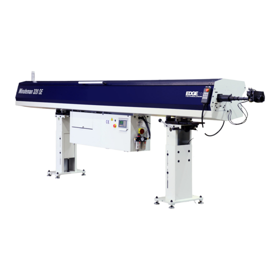
MINUTEMAN 2. Technical Information 2.1 Description of the Machine The Minuteman is a PLC controlled automatic bar feeder designed for both Swiss style and fixed headstock lathes. The bar feeder is constructed to handle a wide variety of material profiles from round to hex and square stocks and can be adapted to feed materials with a more unique shape. - Page 12 MINUTEMAN Following Features • Bar diameter capacity: 3 mm to 27 mm (.118” to 1.062”) • Automatic loading magazine — 10 linear inches of rack capacity • Double pusher, space saving design • Hydrodynamic support via high volume oil flow into channels. •...
-
Page 13: Machine Footprint And Installation Area
MINUTEMAN 2.2 Machine footprint and Installation Area Caution machine placement is important and proper planning should be observed. A level floor free from cracks is ideal for anchoring of the machine. As the customer is the one that decides on machine installation placement it is their responsibility to be aware of proper floor requirements. - Page 14 MINUTEMAN Installation Area The bar feeder must be bolted to a sound, reasonably level floor using anchor bolts. The area surrounding the machine must provide sufficient clearance the operator access to both sides and the rear of the machine as shown in the diagram below. Other necessities are suitable lighting and a compressed air supply.
-
Page 15: Specifications And Capacities
MINUTEMAN 2.3 Specifications and Capacities 2.3.2 Bar Feeder Oil Requirements Caution used oil may contain compounds that could cause skin iratation. Wash skin exposed to used oil. Oil is not consumed by the bar feeder. Oil does not break down from operating in the bar feeder. Oil may become contaminated with debri from bar stock, dust from the environment and lathe back wash. -
Page 16: Guide Channel Specifications
MINUTEMAN 2.3.3 Guide Channel Specifications Warning if bar stock and channel set size are not with in the chart below damage to the bar feeder or lathe could occur. For a complete list of available guide channels offered review the parts section at the end of this manual or visit Edgetechnologies.com Diameter of Bar (MM) Diameter of... - Page 17 MINUTEMAN Bar feeder collet must be correct for the size material. Using the wrong collet can cause production issues. Contact Edge Technologies Parts Department for assistance. ØA ØF M5x0.5 ØF M7x0.75 ØF M8x1.0 ØF M8x1.0 ØF M8x1.0 ØF M10x1.0 ØF M10x1.0 ØF M10x1.0...
- Page 18 MINUTEMAN ØA ØF M5x0.5 ØF M7x0.75 ØF M8x1.0 ØF M8x1.0 ØF M8x1.0 ØF M10x1.0 ØF M10x1.0 ØF M10x1.0 7.5mm OD 12mm OD 15mm OD 16mm OD 18mm OD 20mm OD 22mm OD 23mm OD 15/64” ICOLT075600 ICOLT120600 ICOLT150600 ICOLT200600 1/4” ICOLT075640 ICOLT120640 ICOLT150640 ICOLT200640 ICOLT120700 ICOLT150700...
- Page 19 MINUTEMAN ØA ØF M5x0.5 ØF M7x0.75 ØF M8x1.0 ØF M8x1.0 ØF M8x1.0 ØF M10x1.0 ØF M10x1.0 ØF M10x1.0 7.5mm OD 12mm OD 15mm OD 16mm OD 18mm OD 20mm OD 22mm OD 23mm OD 12.5 31/64 ICOLT151250 ICOLT201250 12.7 ICOLT151270 ICOLT161270 ICOLT181270 ICOLT201270 ICOLT161300 ICOLT181300 ICOLT201300 13.5 ICOLT151350 ICOLT161350 ICOLT181350 ICOLT201350...
-
Page 20: Compressed Air Supply Including Oil
MINUTEMAN 2.3.4 Compressed Air Supply Including Oil Warning working with compressed air, proper PPE is required in accordance with federal state and local laws. Shop air must be present for machine installation 1. The supply hose for compressed air supply must be larger than 8mm 2. -
Page 21: Safety
MINUTEMAN 2.4 Safety Warning safety switches should always be in place during bar feeder operation. The Minuteman is designed to be safe and reliable to operate. However, the machine can be dangerous if used improperly by untrained personnel. Personnel should be familiar with the operating instructions of the equipment before using and must follow standard safety practices. -
Page 22: Emergency Stop Buttons
The lathe will be stuck in emergency stop and the bar feeder will not power up. Please contact Edge Technologies for appropriate instructions. It is the responsibility of the bar feeder and lathe installer to verify emergency stop operation between the lathe and bar feeder is operational. -
Page 23: Electrical Safety
2.3 Specifications and Capacities. Failure to do so may result in injury or damage to the equipment. Normally a bar feeder is ordered from Edge Technologies to be placed with a specific lathe model. The wiring interface is set in accordance with current information received to Edge Technologies. -
Page 24: Electrical Connection
*Note the wiring interface contained in this manual is a generic 1 to 1 pin to wire call out. Each lathe brand is different from one to another. Please contact Edge Technologies for the proper interface schematic if you do not have one. -
Page 25: Glossary Of Terms
MINUTEMAN 2.6.3 Glossary of Terms Common (From Lathe) – This is the 24v DC supply voltage from the lathe for signal sent to the bar feeder control. The voltage cannot be mixed with the bar feeder power supply. Cycle start (bar change end, program start) – Typically a normally open circuit controlled by the bar feeder Cycle Start/M-Code Finish relay. -
Page 26: Signal Functionality And Explanation
MINUTEMAN Door safety – Typically a normally open circuit controlled by the lathe. Voltage is supplied by the bar feed common. The signal prevents the bar pusher from feeding in automatic if the door is open. Circuit can be bypassed. Bar feeder Emergency stop –... - Page 27 MINUTEMAN a crash between the lathe and bar feeder. If the M-code for bar change or feed is never satisfied, it may be an issue with the cycle start signal being set backwards. The first way to correct this issue would be to change the status of the jumper or wire that is controlling the cycle start signal.
- Page 28 MINUTEMAN Bar feeder on- This signal is typically used as a bar feeder alarm to the lathe. IF the lathe is always receiving the signal that the bar feeder is in alarm it will show a message saying that the bar feeder is in alarm.
- Page 29 MINUTEMAN IF wired incorrectly this can cause machines to go into automatic mode when the lathe is not in automatic. IF wired incorrectly this signal can also cause the bar feeder to not allow feeding because the automatic signal is not received. *Needs to be check if wired into the machine interface* To check if this signal is working correctly on the Edge product, put the bar feeder into automatic and check the HMI screen.
- Page 30 MINUTEMAN Chucker Mode: This setting allows the lathe to run without the bar feeder. When chosen the bar feeder sends an auto mode signal to the lathe while remaining in the manual mode. Feed stop- This signal is used to stop the bar feeder from pushing when bar feeder in automatic and collet open.
- Page 31 MINUTEMAN plug, and check that the voltage of the lathe is proper and does not fluctuate beyond safe operating voltage. IF the voltage is in the wrong pin location then simply move the bar feeder voltage to the correct location in the plug. If the voltage is too high or varies too much on the lathe the customer may need to have an electrician come out.
-
Page 32: Transportation And Handling
MINUTEMAN 3. Transportation and Handling Warning The weight of the machine without packaging is approximately 1300 lbs. Only trained operators are to use lifting equipment. Verify the equipment to be used for moving the machine is rated to safely lift the weight of the bar feeder plus the packaging material. -
Page 33: Transportation And Hoisting
MINUTEMAN 3.2 Transportation and Hoisting Hoisting bar feeder Place two steel bars (Diameter: 30mm, length: 1M) under the bar feeder outside of the stands, using suitable lifting straps hoist the bar feeder. Hoisting with bar feeder on pallet Using suitable lifting straps positioned under the pallet near the stands. -
Page 34: Installation
MINUTEMAN 4. Installation 4.1 Lathe Preparation Prior to installing the bar feeder, the lathe installation must be completed and ready to produce parts. If no lathe spindle work holding is installed or no compressed air the bar feeder cannot be installed. -
Page 35: Typical Installation Guide
Purchase Order, as the customer will most likely be in need to initiate an Insurance claim. It is important to always communicate with the Edge Technologies when the equipment sustained any kind of damage. Together we’ll evaluate the situation and formulate a feasible solution designed to overcome the current situation, hopefully even before the customer is exposed to the trouble area. -
Page 36: Swiss Headstock Shipped Components
MINUTEMAN Step 3 Check Inventory. • Adaptation kit. Check parts and test. If not familiar with the application, call Edge Technologies and request an assembly/detail drawing and or pictures. • Guide channel, pushers, collets and noses. Make sure that all is available and correct according to the customer’s pick ticket in the bar feeder. -
Page 37: Fixed Headstock Shipped Components
All Minuteman are shipped as a Swiss style bar feeder with fixed headstock components. Items include a hard nose and nose liner. Installation requires the use of these additional components sold by Edge Technologies. Step 4 Lathe Condition While field retrofits on existing lathes maybe challenging when it comes to the presence of an effective and properly documented electrical interface, the installation on new lathes requires us to perform a comprehensive assessment as well. - Page 38 MINUTEMAN c. Head stock adaptors d. Correct channel set installed e. Threaded rod, bracket, and nuts Telescoping or hard nose g. Hardnose nose insert, if required h. Bushing blocks or rollers MAVD if equipped 5. Calculate bar feeder positioning a. Consider lathe headstock stroke b.
- Page 39 MINUTEMAN i. Verify collapsibility of telescoping nose ii. Verify Reach of telescoping nose 11. Connect synchronization rod a. Cut threaded rod, as required b. Adjust stroke of synch rod on bar feed c. Verify axial shift synch switch adjustment, adjust as required 12.
-
Page 40: Distance From Lathe
MINUTEMAN 4.3 Distance From Lathe Caution verify proper installation distance or machine crash may occur. Verifying the proper install location is critical for complete material utilization and collapsing of the telescoping nose. The bar feeder must be set the proper distance from the lathe. The set distance from the bar feed to the lathe is 1346 mm (53 inches). -
Page 41: Height Adjustment
MINUTEMAN 4.4 Height adjustment Caution the assembly of the level pad mounting system must be completed with all the parts for proper installation. Caution only trained installers are to make stand adjustments. Not following proper procedure could lead to personal injury and The Minuteman utilizes a simple stand system for height adjustment. - Page 42 MINUTEMAN Loosen the 8 stand screws Adjust the screw (2) up or down to achieve correct height. Adjust the bar feed height to center the channel to the lathe spindle. REV 13.1:2020...
-
Page 43: String Alignment
Not supplied is the rear centering plug and spindle plug. These items can be made for the string alignment. These items are not available from Edge Technologies. The string is included with all Minuteman models. The standard alignment procedure by an Edge Technician is by laser alignment. - Page 44 MINUTEMAN Remove the bar pusher out and insert a centering plug, pull the nylon string from the lathe A, to the end of the bar feeder B. Select a proper plug size for lathe the collet, insert and close lathe collet, move lathe Z axis to –Z over travel, pull the nylon string tight and secure in place.
-
Page 45: Laser Alignment
MINUTEMAN 4.6 Laser Alignment. Warning use protected eyewear when using a laser during bar feeder alignment. The preferred method of aligning the bar feeder is by way of a laser aligning. The instructions below are general in nature. Follow the laser tool manufactures instructions for laser usage. Caution disabling the hood switch on the bar feeder is required to view the laser target and align the bar feeder. -
Page 46: Axial Shifting
MINUTEMAN 4.7 Axial Shifting Warning incorrect machine placement may cause catastrophic damage to lathe or bar feeder. Caution all axial shift safeties must be adjusted and set correctly Caution bar feeder must be in emergency stop prior to axial shifting bar feeder. - Page 47 The correct shift limit position must be set for the lathe application. This is normally set from Edge Technologies with the most current information on hand of the lathe manufacture. There are times the lathe manufacture will change lathe specifications and not notify Edge Technologies.
- Page 48 The Position stop screws allow an axial stroke to be set to one of 3 positions. Once the bar feeder has been installed changes to this screw position must not be changed. The position will be determined by Edge Technologies to the lathe model. Axial stop screw location REV 13.1:2020...
- Page 49 MINUTEMAN The graphic below represents the bar feeder movement and head stock movement during the Swiss and Chucker change. Guide Headstock Bushing Bar feeder is anchored down to floor and equipped with axial shift option Guide bushing removed and headstock in chucker Bar feeder shifted into chucker position position REV 13.1:2020...
- Page 50 Edge and lathe manufacture application information. If the bar feeder was prepped and shipped from Edge Technologies the axial shift position will be set according to the lathe. On occasion a bar feeder from a dealer or a used bar feeder may have axial track settings for a different lathe than originally prepped for.
- Page 51 MINUTEMAN Axial shift setting options. The specific Position Movement length position is based on the following 120mm parameters. 160mm • Chucker/Swiss position 230mm • Pusher reach distance When position 2 is to be used, remove • Bar feeder material loading position screw from position 1 and place it into hole position 2.
-
Page 52: Setting Axial Track Synchronization Switches
MINUTEMAN 4.8 Setting Axial Track Synchronization Switches Caution setting of the synchronization switches is extremely Important to reduce a possible crash between lathe and bar feeder. Caution Place bar feeder and lathe into emergency stop when setting switch positions The first step in proper switch positioning is placing the synch rod block in the correct position. See section for setting of the synch block. - Page 53 MINUTEMAN The outer switch location is not adjustable. The adjustement will come from trimming the switch plate attached to the synchronization belt slide. • The synch belt covers (A) must be removed to gain access to the switch plate (B). •...
-
Page 54: Change Axial Swiss Mode To Chucker Mode
MINUTEMAN 4.9 Change Axial Swiss Mode to Chucker Mode Caution bar feeder must be in emergency stop prior to axial shifting bar feeder. Caution all attaching components must be installed and tightened prior to production. Caution only trained personnel should be converting the lathe and bar feeder to Swiss or chucker option. -
Page 55: Change Chucker Mode To Swiss Mode
MINUTEMAN 4.10 Change Chucker Mode to Swiss Mode Caution bar feeder must be in emergency stop prior to axial shifting bar feeder. Caution all attaching components must be installed and tightened prior to production. Caution only trained personnel should be converting the lathe and bar feeder to Swiss or chucker option. -
Page 56: Axial Track Programing Tech Tip
MINUTEMAN 4.11 Axial Track Programing Tech Tip Anytime bar feed configuration is changed from one operational mode to another certain position parameters must be changed in order for proper operation. If these parameters are not changed machine alarms can be produced or excessive remnants will be observed. During initial setup it is required to measure and record the following •... -
Page 57: Nose Block Alignment
MINUTEMAN 4.12 Nose Block Alignment Caution do not adjust nose block when electrical power is applied to bar feeder. The nose block is aligned by way of 4 jack screws at the mounting flange of the nose block device. The vertical mounting plate holes on the bar feeder are threaded for the bushing block mounting flange. - Page 58 MINUTEMAN REV 13.1:2020...
-
Page 59: Anchoring
MINUTEMAN 4.13 Anchoring Warning do not install level pads over cracked concrete with uneven surfaces. Warning drilling anchor holes at an angle may affect the final aligning of the bar feeder. Caution wear protective eyewear when operating a hammer drill or hammer to strike a floor anchor. -
Page 60: Installation Components
MINUTEMAN 4.14 Installation Components Spindle Liner: Used to reduce spindle diameter to support the pusher. Some applications do not require a spindle liner. This is true when the spindle bore diameter is the same as the pusher. Fixed front nose and insert: This nose is cut to fit and used on fixed headstock lathes. If multiple inserts. -
Page 61: Spindle Liner
13mm from the rear of the chuck jaws or collet. Any further and this could cause a load or remnant ejection issue Normally a spindle liner will be part of the options ordered from Edge Technologies. Additional spindle liners may be order from Edge technologies. -
Page 62: Telescoping Nose
MINUTEMAN 4.16 Telescoping Nose Caution cutting of the telescoping nose should be carefully performed. The telescoping nose is normally used with sliding headstock lathes and attaches from the bar feeder to the MAVD when equipped. The Minuteman may be equipped with a 3 stage or 4 stage telescoping nose depending on lathe application. - Page 63 MINUTEMAN The bushing is directional, Note the offset of the retaining hole. Warning machine damage may occur if telescoping nose is not properly securred to lathe headstock. Be sure the retaining ring and plate fit flush and completely inserted into the diameter of each. Collet Bushing The MAVD collet screws are offset...
- Page 64 MINUTEMAN When using small diameter bar stock the use of the MAVD and AVD are normally ill advised. The telescoping nose will have aditional insert lengths to pass into the MAVD and/or AVD clamping areas. The small insert on the MAVD side must not be cut. When the nose must be cut remove the insert and trim the 3 stage of the nose.
- Page 65 MINUTEMAN Telescoping Nose Measuring and Cutting 1. Move lathe Z axis to –Z over travel position. 2. Measure from face of nose adapter (A) on bar feeder to inside shoulder (B) of moveable anti-vibration device on lathe. Note measurement (#1). 3.
- Page 66 MINUTEMAN 10. Slide on nose (C) into nose adapter (H) up to point (D). Grove (D) will be flush with face (A). 11. Tighten screws to hold nose in place. Warning use extreme care and alertness when performing the following step. 12.
-
Page 67: Hard Nose
MINUTEMAN 4.17 Hard Nose Caution cutting of the hard nose should be carefully performed. The hard nose on the Minuteman is cut to size once the bar feeder is aligned and anchored. The oil gathering device is then attached to the end of the nose for ejected oil to gather and return to the with a drain hose to the bar feeder. -
Page 68: Mavd Installation
When installing the MAVD all headstock adaption components must be installed. All adaption prints are shipped with the prepped bar feeder from Edge Technologies for the appropriate lathe. MAVD alignment may only be performed once the Minuteman is aligned and anchored to the floor. - Page 69 MINUTEMAN A/D MAVD shown Remove the 2 attaching screws 6. Press the emergency stop button on the lathe and bar feeder. 7. Remove the compressed air supply from the bar feeder. 8. Reverse the 2 airlines at the MAVD air cylinder. This will allow the MAVD to close on the pusher when air is reconnected.
- Page 70 MINUTEMAN Loosen 4 attaching screws, 2 on each side. 11. Unscrew the MAVD close screw to allow the rollers to grip the pusher. Caution pinch hazard if proper observation is not adhered Loosen the lower lock nut and rotate the screw counterclockwise until all 4 rollers make equal contact with the pusher.
-
Page 71: Avd Centering
MINUTEMAN 4.19 AVD Centering Warning AVD bar adjustment must be performed anytime the centering procedure has been performed. The AVD (Anti Vibration Device) is located at the exit point of the bar feeder. This roller steady functions similar to the MAVD to manage vibrations, however the AVD is stationary. The AVD centering may be adjusted through the end plate slide holes. - Page 72 MINUTEMAN Use a long reach allen wrench to access the mounting screws. Caution lathe and bar feeder must be powered on to adjust the AVD roller/block settings. Warning the correct spindle liner must be installed in the lathe spindle according to the pusher diameter.
-
Page 73: Synchronization Connecting Rod
MINUTEMAN 4.20 Synchronization Connecting Rod Caution do not operate without synchronization rod securely connected. Machine damage will occur. Warning always double check required length of the synch rod prior to trimming. The synchronization connecting rod allows the mechanical connection between lathe and barfeed which allows synchronized movement between the lathe z axis, material, and barfeed pusher when lathe collet is closed. - Page 74 MINUTEMAN Caution lathe and bar feeder must be powered for installation synch rod installation. Warning lathe must be aligned and anchored for synch rod cutting and installation. If the length of the synch rod is in question follow the procedure to determine the length of the rod. Synchronization Connecting Rod Measurement 1.
- Page 75 MINUTEMAN 7. Connect adapter (G) to swivel (B) and tighten. 8. Connect adapter (G) to synchronization rod (H) with screws supplied. 9. Gap (I) should be approximately 12.7mm (.500”).Adjust the length of the rod as required. 10. Synch rod should never make contact with bar feeder. Move lathe Z axis forward and back checking for smooth operation and clearance of synchronization rod (H), adapter (G) and threaded rod (A).
-
Page 76: Drip Pan
Swiss headstock as it moves towards the bar feeder. The lathe sheet metal should be cut so the drain pan may be as long as possible without crashing the headstock. Extra-long drain pans are available from Edge Technologies. The drain pan can be cut based on the application. - Page 77 MINUTEMAN Caution when removing or installed the drip pan be sure lathe and bar feeder are in emergency stop. The tray setup with the retaining ring is used only on the 3 stage nose. Installation steps of the drip pan MAVD must be installed and telescoping nose must be cut to installation length.
-
Page 78: Hardnose Oil Collector
MINUTEMAN 4.22 Hardnose Oil Collector Caution install the hardnose when lathe and bar feeder is in emergency stop. The oil collector on the hard nose is plumbed to allow oil flow back to the bar feeder. The inside diameter of the hard nose must match the pusher and guide channel set. When measuring the distance requirements, be sure the lathe spindle liner is installed. -
Page 79: Systems And Adjustments
MINUTEMAN 5. Systems and Adjustments 5.1 Bar feeder Component Locations REV 13.1:2020... -
Page 80: Magazine Adjustment
MINUTEMAN 5.2 Magazine adjustment Follow the procedure below anytime the bar diameter requires changing. Caution when adjusting the magazine be sure the lathe and bar feeder is in emergency stop Caution, adjusting the magazine can produce pinch points between magazine and material Caution when lifting material into the magazine, 2 or more people or a lifting device may be required to load material 1. - Page 81 MINUTEMAN When adjustming the magazine do not loosen or tighten nuts. Only move the large allen bolt to make adjustments. Adjust allen bolt for material diameter loading Do not loosen or tighten nuts. REV 13.1:2020...
- Page 82 MINUTEMAN 5.3 AVD/MAVD Adjustment Proper adjustment of the Anti-Vibration Device (AVD) and Movable Anti-Vibration Device (MAVD) is important for proper machine operation. Proper adjustment will help support the bar and possibly reduce vibrations during production. Warning lathe and bar feeder must be in a manual mode during the adjustment of the Anti-Vibration Device/Movable.
- Page 83 MINUTEMAN AVD adjustment screw (A) and lock nut. If the open stop must be adjusted removing the cover will aid in accessing the screw and lock nut. REV 13.1:2020...
- Page 84 MINUTEMAN Adjustment screw (B) Lock nut (A) MAVD/AVD Open MAVD/AVD Speed Valve Closed Speed Valve 5. Tighten screw A until the rollers just touch the bar. Rotate the screw to back off the rollers from the bar 1 full turn. Lock jam nut B 6.
- Page 85 MINUTEMAN MAVD Open Speed Valve Open adjustment screw MAVD Closed Lock nut (C) Speed Valve Adjustment screw (D) Close adjustment Lock nut (A) Adjustment screw (B) Warning improper MAVD adjustment can lead to premature roller wear. Adjustment to the open and close speed of the MAVD/AVD is by way of the thumb screws on the cylinder.
-
Page 86: Avd Roller/Block Replacement
MINUTEMAN 5.3.2 MAVD Block Sets Warning the block sets must be used in same sized pairs. The use of bushing blocks may assist with optimizing the bar feeder performance with certain material, shapes, and operating speeds. 2 Blocks of the same size are required for each MAVD. Choose a block size that is 2mm larger than your working diameter. - Page 87 MINUTEMAN Remove the upper access plate Loosen retaining screws, do not remove screws. The cover is slotted, remove AVD top cover. 6. The center socket head cap screw retaines the roller block. The 2 outer socket head cap screws must stay in position for roller block alingment.
- Page 88 MINUTEMAN Remove AVD access plate 8. Once cover is removed, locate the long 10mm hex screw. Remove this screw, pull the roller block up to clear the SHCS alingment screws. Do not remove the SHCS alingment screws. 9. Remove both roller sets from the AVD 10.
-
Page 89: Pusher Drive Belt
MINUTEMAN 5.5 Pusher Drive Belt Adjustment Caution bar feeder and lathe must be emergency stop for belt adjustment Warning properly trained personnel are required to adjust drive belt The pusher drive belt is connected to the carriage. The belt runs the length of the machine contained inside of a channel. -
Page 90: Synchronization System
MINUTEMAN 5.6 Synchronization System Caution Warning operation of the synchronization will move at random times during the automatic operation. Access covers to the synch device should always be in place during operation. Caution belt adjustment should only be performed when bar feeder electrical power has been removed. - Page 91 MINUTEMAN Synchronization Belt Adjustment Warning when adjusting synch belt place lathe and bar feeder into emergencey stop. Catuion do not operate bar feeder with synch belt covers installed. 1. Place bar feeder in emergency stop. 2. Open the bar feeder hood. Remove synch belt cover.
- Page 92 MINUTEMAN 7. Once the adjustment has been made secure the adjustment plate lock screws (2). 8. Tighten the adjustment screw lock nut (1). Check belt deflection, readjust as required. Reinstall belt cover. Veify all tools have been removed and all machine gaurding is in place prior to resetting the emergency stop.
-
Page 93: Channel Set Components
The channel set on the Minuteman may be changed to a variety of sizes. It is important to note the material diameter to be used in the bar feeder fits in the proper channel set. Channel set components are specific to each channel set. Contact Edge Technologies for additional channel sizes and sets. - Page 94 All components with in a channel set is specific to the size of that channel set. Combining the channel; sets will not work properly and will produce poor bar feeder performance. For available guide channel sets reference this manual or contact Edge Technologies for the most up to date information.
-
Page 95: Pre-Run Setup Card
MINUTEMAN 5.8 Pre-Run Setup Card The following card may be printed, laminated, and placed near the Minuteman. Great for the changeover tech. Pre-Run Setup Follow bar feed and lathe manufactures instructions on machine changes All bar feed and Lathe safety’s installed and functional Air pressure set at 75-90 PSI (5-6 bar) Proper oil viscosity and oil level set... -
Page 96: Pre-Feed Pusher And Pusher
MINUTEMAN 5.9 Pre-feed Pusher and Pusher Caution do not replace pusher or pre-feeder pusher with electrical power applied to lathe or bar feeder. Warning the correct pusher length must be used for the correct length of bar feeder or machine damage may occur. The pre-feed pusher and pusher diameters must match as a set with the corresponding guide channel and components sizes. - Page 97 MINUTEMAN The pusher flag is physically locked into the press plate. A small metal block is used to spring closed to keep the pusher flag locked in place. Stop plate is adjustable for the compression of the Pusher flag locks spring block.
- Page 98 MINUTEMAN When the carriage is fully retracted back the spring block is captured by the stop plate. This allows the pusher flag to be clear of the press plate and raised. There is a small Adjust screw so adjustment screw positive so there is located on the approximant 1mm...
-
Page 99: Rotating Tip
MINUTEMAN 5.10 Rotating Tip Warning the rotating tip should match the diameter of the pusher. Running too small or too large of a rotating tip diameter will cause damage. The rotating tip used in the Minuteman is designed for many hours of operation. A few different tips sizes and collet attaching methods are available. -
Page 100: Channel Set Replacement
MINUTEMAN 5.11 Channel Set Replacement Warning set the lathe and bar feeder emergency stops prior to channel change over. When changing the channel set it is important to remove then replace one item at a time. If you get ahead of yourself it may take longer setting up the new channel set. The channels pieces are directional and may be installed 180 degrees off. - Page 101 MINUTEMAN Channel sections will contain an oil port that is molded into location. This hole should line up with the oil hole in the channel. The channel is fastened in place by an interference fit. No fasteners are required to be used. If the channel section is pushed up from the channel lowering the oil pump will reduce this issue.
- Page 102 MINUTEMAN The AVD and MAVD will contain an anchor that assist in pusher support. Each channel set will contain 2 of these anchors and will match the pusher set. MAVD show Be sure the telescoping nose is properly attached when reinstalled. REV 13.1:2020...
-
Page 103: Material Measurement Sensor/Cutting Sensor
Note if the measurement sensor is in the wrong state of position, bar changes will not occur. The standard cutting sensor trip plate is designed for bar stock larger than 2mm. If 2mm and smaller bar stock is to be used a new trip plate may be obtained from Edge Technologies. REV 13.1:2020... -
Page 104: Gripper Assembly
MINUTEMAN 5.15 Gripper Assembly Caution the Gripper is a pinch hazard. Caution the Gripper assembly is a moving component that should always be service with electrical power and air supply removed. Caution place lathe and bar feeder into emergency stop when replacing gripper jaws. - Page 105 MINUTEMAN Adjusting parameter “First Feeding Distance” to fine tune the press upon and press off performance. The gripper assembly is a pnumatic/mechanical design. The closing and opening command of the gripper is by the PLC. The PLC directly controls the air solenoid coil. Once the air valve is energized the pnumatic cyclinder moves a gear set to open and close the gripper jaws.
-
Page 106: Shuttle - Extraction / Introduction Cylinder
MINUTEMAN 5.14 Shuttle - Extraction / Introduction Cylinder Caution never adjust the air valves without being properly trained The Minuteman is equipped with a robust extraction and insertion system designed to provide exceptional durability. The operation of this cylinder is known as the shuttle. During introduction of the bar feeder collet onto the bar end, the servo drive motor is engaged with the shuttle (air cylinder) moving simultaneously. -
Page 107: Procedure For Checking Bar Straightness
MINUTEMAN 5.15 Procedure for Checking Bar Straightness (Reference ASTM B249) 1. Find a suitable surface to allow the bar to rest on V-blocks without any rocking movement. 2. Rotate the bar 360°. Record the dial indicator readings at each location. 3. -
Page 108: Bar Stock Preparation
MINUTEMAN 5.15.1 Bar Stock Preparation The bar stock must be free of burrs, chips and excessive dirt. Clean bars will extend the life of the channel guides and bearing unit of the pusher as well as the oil pump impeller. The bar ends should be relatively square to the length of the bar. -
Page 109: Vibration Troubleshooting Check List
MINUTEMAN 5.18 Vibration Troubleshooting Check List REV 13.1:2020... -
Page 110: Control Operation And Hmi Description
The HMI is a microprocessor based, touch screen unit that receives the user input commands directly through the keypad. There are many obvious defined buttons or keys when pressed an action of some type appears on screen. The HMI is programmable and the software may be updated by Edge Technologies. REV 13.1:2020... - Page 111 MINUTEMAN Do not use harsh cleaning chemicals on the HMI screen. Clean the screen with the power off. Use of a micro fiber cloth towel and denatured alcohol is permissible. Basic HMI navigation Distance the pusher There are 9 “F” key position from the home menus.
- Page 112 MINUTEMAN The monitor screen displays the following items while in auto, • Pusher position – Position of pusher from bar feeder zero • Material remaining – amount of material left on bar being machined • Parts remaining – amount of parts left on bar being machined •...
-
Page 113: Handheld Pendant
MINUTEMAN 6.2 Handheld Pendant Layout Function Emergency STOP Pre Auto Pre Auto light Manual clamping Manual advance (Right) Manual retreat (Left) Origin point light (Left) Chuck open light Allow feeding on Manual mode Manual mode light Manual Gripping in/out Pusher extracted Manual channel open/close Channel down light... -
Page 114: Power Up
MINUTEMAN 6.3 Power up: To Power Up and Place the Bar Feeder In Automatic (must have bar stock loaded in bar feeder and lathe ready for production) 1. Check to make sure the emergency stop buttons on the pendant and the main control panel are released. -
Page 115: Basic Movement Functions
MINUTEMAN 6.4 Basic Movement Functions Warning proper training is required for bar feeder operators. A lack of training may lead to personal or machine damage. Warning be sure lathe is ready for bar feeder operation. ( 6.4.1 ) Advance / retreat at low-speed (Creep) (When the lathe on the left, the motion of are opposite). -
Page 116: Loading And Unloading Bar Stock
MINUTEMAN Once bar is in the lathe collet and at facing position, the barfeed will time out after 20 sec. with an alarm unless the lathe collet is closed or the manual button on the bar feeder is pressed. 6.5 Loading and Unloading Bar Stock Warning proper training is required for bar feeder operators. - Page 117 MINUTEMAN 2. The pre-feed pusher will move the bar forward to position and the grippers will close on the bar. 3. The pre-feed pusher will retract. 4. The shuttle will pull the pre-feed pusher to the rear limit. 5. The guide channel will close. 6.
-
Page 118: Tower Light
MINUTEMAN 6.6 Tower Light The indicator light provides quick visual indication of bar feeder status. The bar feeder PLC directly controls the operation of the tower light. Status conditions below, • Red light is on, bar feeder is in emergency stop. •... -
Page 119: Parameters And Program
Note normally parameters set during the installation process are normally not adjusted. See parameters list in this manual. Edge Technologies reserves the right to make programming modifications to the HMI and PLC software. As of the printing of this manual the current software available is represented with in this manual. - Page 120 MINUTEMAN The monitor screen displays the following items while in auto, • Pusher position – Position of pusher from bar feeder zero • Material remaining – amount of material left on bar being machined • Parts remaining – amount of parts left on bar being machined •...
-
Page 121: F1 - F4 Parameter Screen Settings Worksheets
MINUTEMAN 7.1 F1 – F4 Parameter Screen Settings Worksheets Caution making changes to parameter screens require thorough knowledge of the bar feeder system. Only trained operators may make adjustments. The following parameter pages will indicate which parameters are to be set during installation and for part change over. -
Page 122: F2 Fixed Parameter
MINUTEMAN F2 Fixed parameter Symbol Default Description Installed Setting # 1435 mm Facing position # 3920 mm Max. pusher forward travel # 2550 mm First anti-vibration opening position # 3200 mm Second anti-vibration opening position # 2200 mm Third anti-vibration opening position #... - Page 123 MINUTEMAN F3 Fixed parameter Symbol Installed Setting Default Description # On/off F4: Demo Mode # Swiss/Fixed F5: Swiss # On/Off F6: Cont Feed # Roller/Bar F:4 Bar Loader Enter # Extract/Eject F:6 Front Eject password # With/Without F:4 MAVD W/O Collet #...
- Page 124 MINUTEMAN F1 Turning parameter Setting unit Range Suggested setup mm/In 0~9999 New part length Change this parameter each time part length changes. Description: Part length + cutoff tool width = Total part machining length. Setting method: Parts remaining is calculated based on this parameter and max pusher Note: travel.
- Page 125 MINUTEMAN F1 Turning parameter Setting unit Range Suggested setup 0~99 Sets the pusher forward torque in automatic with lathe collet closed. Description: According to material size and in relation with the speed of collet close. Setting method: Adjust in small increments to avoid bending of material. Note: Setting unit Range...
- Page 126 MINUTEMAN F1 Turning parameter Setting unit Range Suggested setup Short 25 ~ 50 mm from mm/In 0~9999 Movable anti-vibration The movable anti–vibration opening position allows the pusher to Description: proceed past the movable anti–vibration device in automatic mode. Value must be changed accordingly each time lathe Z axis re-chuck position is changed.
- Page 127 MINUTEMAN Value is initially set to zero upon arrival at customer, please set during Note: installation. Oil pump will come on once barfeed is in automatic. F1 Turning parameter Setting unit Range Suggested setup Product length + cutoff + mm/In 0~999 5~30mm When pusher moves further than value set in automatic, when...
- Page 128 MINUTEMAN F1 Turning parameter Setting unit Range Suggested setup Sync. Device disengagement position = The product mm/In 0~999 length + cutoff length – 10mm The synchronization device will disengage prior to lathe collet opening Description: so when lathe headstock moves to rechuck position, no delay is needed between lathe collet open and Z axis movement.
- Page 129 MINUTEMAN F1 Turning parameter Setting unit Range Suggested setup mm/In 0~ 4294967295 Set as required Allows the user to program 2 different length part programs in the lathe. Description: This is helpful when the remnant length is long enough to produce shorter parts reducing waste.
- Page 130 MINUTEMAN F2 Fixed Parameter Setting unit Range Suggested setup mm/In 0~9999 Depend on actual length Position of new bar loaded automatically by bar feed. All bars Description: regardless of length will load to this position when bar feed is in automatic.
- Page 131 MINUTEMAN F2 Fixed Parameter Setting unit Range Suggested setup mm/In 0~999 Depend on actual length Maximum distance pusher can feed into lathe. Description: Sliding headstock : Move lathe Z axis to over travel position toward Setting method: guide bushing. In manual mode move pusher forward until pusher collet stops moving against lathe, subtract 5mm from current pusher position and set value.
- Page 132 MINUTEMAN F2 Fixed Parameter Setting unit Range Suggested setup mm/In 0~9999 3200mm/12ft model The second anti–vibration device will open just prior to the pusher flag Description: reaching the second anti-vibration device. (Channel section nearest AVD) In manual jog pusher forward until pusher flag is 80-120mm away from Setting method: second anti–vibration device.
- Page 133 MINUTEMAN F2 Fixed Parameter Setting unit Range Suggested setup mm/In 0~9999 1350mm/12ft model The Forth anti–vibration device will open just prior to the pusher flag Description: reaching the second anti-vibration device. (3 channel section nearest AVD) In manual jog pusher forward until pusher flag is 80-120mm away from Setting method: forth anti–vibration device.
- Page 134 MINUTEMAN F2 Fixed Parameter Setting unit Range Suggested setup 0~10 0.5 sec Delay after new bar reaches facing position before cycle start signal is Description: sent from bar feed to lathe. Enter value required for delay. Setting method: The longer the set time the longer bar change will take Note: Setting unit Range...
- Page 135 MINUTEMAN F2 Fixed Parameter Setting unit Range Suggested setup 0~999 0.5 sec Time pusher will continue to push bar after collet closes when in Description: automatic (Collet open speed and torque parameters are used). Enter value required to continue pushing. Setting method: Adjust only for time difference between when lathe collet open signal is Note:...
- Page 136 MINUTEMAN F2 Fixed Parameter Setting unit Range Suggested setup 0~999 Speed pusher returns at during bar change. Description: Enter the value needed for return speed. Setting method: Return speed starts once pusher moves 200mm during return move. Note: REV 13.1:2020...
- Page 137 MINUTEMAN F2 Fixed Parameter Setting unit Range Suggested setup mm/In 0~999 0.5 sec Time pusher will continue to push bar after collet closes when in Description: automatic (Collet open speed and torque parameters are used). Enter value required to continue pushing. Setting method: Adjust only for time difference between when lathe collet open signal is Note:...
-
Page 138: F3 System Function
MINUTEMAN F3 System Function Setting unit Range Suggested setup On / Off On / Off Sets the barfeed to demo mode. (Set collet open and bar change to on) Description: Demo Mode Select to turn demo mode on or off. Setting method: Not for use by end user Note:... - Page 139 MINUTEMAN F3 System Function Setting unit Range Suggested setup Front Front Eject/Extract Extract Eject/Extract Select removal method of remnant Description: Front Eject During bar change the barfeed will pull the remnant back with the Extraction: pusher, the grippers will check the remnant was pulled out of the lathe spindle and drop the remnant in the catch pan.
-
Page 140: Feed Stop Latch
MINUTEMAN F3 System Function Setting unit Range Suggested setup Normal / Latch Normal / Latch Normal When lathe collet opens normal setting allows bar feeder to feed. When Description: latch is set bar feeder must receive a signal from lathe when collet is Feed Stop open. -
Page 141: F4 System Function
MINUTEMAN F4 System Function Setting unit Range Suggested setup mm/In 0 - 99999 Depend on actual position The position the pusher starts slowing down while it returns to the Description: home position Setting method: Note: Setting unit Range Suggested setup mm/In 0 - 99999 Depend on actual position... -
Page 142: Maintenance
MINUTEMAN 7. Maintenance 7.1 Maintenance Chart Warning prior to bar feeder maintenance turn off 3 phase power to the bar feeder and place the lathe into emergency stop Warning prior to pneumatic system service be sure to evacuate the system. Observe the following guidance •... -
Page 143: Inspecting The Air Regulator
MINUTEMAN Warning always use proper eye protection when working with compressed air systems. 7.1.3 Inspecting the air regulator • Check the bottle (B) for water. • Press button (C) to exhaust water out of bottle. Inspect for the following • Air leaks •... -
Page 144: Air Control Valves
MINUTEMAN 7.1.5 Air Control Valves Warning when servicing the air system use proper personal protective equipment. Warning only trained service technicians are to perform maintenance and service to the air system. Warning discharge the air system prior to disconnecting component air lines The air system valve solenoids on the Minuteman are directly controlled by the PLC. - Page 145 MINUTEMAN REV 13.1:2020...
-
Page 146: Air Component Identification Chart
MINUTEMAN 7.2 Air Component Identification Chart REV 13.1:2020... -
Page 147: Troubleshooting
8. Troubleshooting Caution troubleshooting and diagnosis of the bar feeder must be carried out by a trained and qualified technician. Contact Edge Technologies if a qualified technician is unavailable. The PLC monitors various systems with in the bar feeder. When problems are detected with in this system an alarm code will be displayed on the HMI. - Page 148 MINUTEMAN Material feeding failure Situation Cause Solution Material can't feed into the The center of the bar feeder Re-adjust the alignment spindle smoothly and the lathe isn't correct Material can't feed into the The front of the material is too Chamfering before loading chuck of the lathe smoothly rough.
-
Page 149: Alarm01
MINUTEMAN Alarm NO. ERROR/CAUSE CURE Check for pusher obstruction. Pusher cannot return to home Alarm01 Adjust home return speed during bar change Pusher moved further than set value with collet Alarm02 Long feed safety open, check parameter, check lathe collet. Pusher moved less than set value when collet Alarm03 Short feed safety... -
Page 150: Alarm 15
MINUTEMAN Alarm NO. ERROR/CAUSE CURE Material length is too short to load automatically Alarm15 Material is too short. Barfeed cannot reach facing Check material for burr or chamfer, check the Alarm16 position value of facing position. Lathe failed to start after cycle Check lathe wiring for receiving of cycle start Alarm17 start... -
Page 151: Alarm 94
MINUTEMAN Cannot Go Into Auto While The Alarm 94 Close the lathe collet Collet is Open Hood Not closed while Operating Alarm 95 Close the hood Channel Hood Not Closed During Insertion Alarm 96 Close the hood or Extraction Hood not closed During Gripper Alarm 97 Close the hood Actuation... - Page 152 The following list reflects the alarms available with the servo drive. The list is just to guide the operator through basic troubleshooting. Only factor trained technicians should attempt to diagnose internal problems. Contact Edge Technologies for further troubleshooting.
- Page 153 MINUTEMAN REV 13.1:2020...
- Page 154 MINUTEMAN REV 13.1:2020...
- Page 155 MINUTEMAN REV 13.1:2020...
- Page 156 MINUTEMAN REV 13.1:2020...
- Page 157 MINUTEMAN REV 13.1:2020...
-
Page 158: Mr-Je-40A Servo Configuration
MINUTEMAN MM320 MR-JE-40A Servo Configuration Warning do not make changes to drive setting different than the list below. Doing so will cause failure to drive and/or servo. Warning use the parameter settings for the specific drive. Using the wrong drive values will cause damage. **The MR-JE-40A servo drive is the latest drive in the C320. - Page 159 MINUTEMAN MM320 MR-JE-40A Servo Drive Settings REV 13.1:2020...
-
Page 160: Mr-E-40Ag Servo Configuration
MINUTEMAN MM320 MR-E 40AG Servo Configuration Warning do not make changes to drive setting different than the list below. Doing so will cause failure to drive and/or servo. Warning use the parameter settings for the specific drive. Using the wrong drive values will cause damage. **The MR-JE-40A servo drive is the latest drive in the C320. - Page 161 MINUTEMAN Description of Alarm 23 Warning do not change overload amperage settings with power on to the bar feeder. Warning reset the overload when power is removed. Oil pump overload In normal operation identification window is blue. The identification window will show “T” up when overload is tripped.
-
Page 162: Resetting Emergency Stop Safety Interlocks (Essi)
MINUTEMAN Resetting Emergency Stop Safety interlocks (ESSI) Caution the emergency stop switches must be set correctly to keep lathe and bar feeder from crashing together. Caution all covers must be in place once adjustments have been made Caution the reset procedure requires proper training to do so. In the event of operating the lathe headstock and bar feed outside the intended design envelop, will cause a bar feed safety interlock to engage. - Page 219 Minuteman Parameter Record Customer: HMI Version Bar feeder Model: S/N: Lathe Model: S/N: Service Technician PLC Version Date: Distance From Lathe: Center Height: F1 Turning Parameter Part Length + Cut Off Tool Width First Feeding Speed Collet Open Pusher Speed Oil Pump Shutoff Position Collet Open Pusher Torque Long Feed Safety Max.
- Page 220 Minuteman Parameter Record F2 Fixed Parameters Facing Position __________________________ in Barchange Return Delay __________________ Maximum Pusher Forward Travel ___________ in Pushing After Collet Closed _______________ AVD Opening Position _________________ Closed Collet Timeout ____________________ AVD Opening Position _________________ Open Collet Timeout _____________________ AVD Opening Position _________________ Barchange Return Speed _________________% AVD Opening Position _________________...
- Page 221 Minuteman Parameter Record F3 Particular Program Modify (Continued) F3 Page Continue F4: Feed Stop: Normal Feedstop Latch Do Not Feed After EOB Feed After EOB F4 Slow Down Positions Home Slowdown Position Pre-feed Slowdown Position F7 Change MM/IN Mode F8 Program Version PLC ____________________ _____________________ F9 Signal Test...
- Page 222 OPERATIONS MANUAL OPERATIONS MANUAL Version 13.1 Technical data subject to change without notice EDGE TECHNOLOGIES PRODUCTIVITY SOLUTIONS PROVIDER 11600 ADIE ROAD MARYLAND HEIGHTS, MO 63043 314.692.8388 f 314.692.5152 www.edgetechnologies.com...
Need help?
Do you have a question about the Minuteman 320 SE and is the answer not in the manual?
Questions and answers