Table of Contents
Advertisement
Quick Links
Advertisement
Table of Contents

Related Manuals for Edge Technologies V-65 Series


Summary of Contents for Edge Technologies V-65 Series
- Page 2 V-65 Series SHORT BAR FEEDER REBEL-V-65E/LE-A MANUAL FOR USE AND MAINTENANCE REV. 08 DATE: : : : 2016/06/01 COD: : : : BRV104032...
-
Page 3: Table Of Contents
INDEX V-65E-A CONTENT( ( ( ( INDEX) ) ) ) GENERAL INFORMATION Contents of the manual ----------------------------------------------------------------- 1-1 The label of manufacturer and bar feeder ----------------------------------------- 1-2 Support of technique -------------------------------------------------------------------- 1-2 DATA OF TECHNIQUE Introduction of the bar feeder --------------------------------------------------------- 2-1 Machine size ------------------------------------------------------------------------------ 2-2 Description -------------------------------------------------------------------------------- 2-2 Compressed air supply and power supply ----------------------------------------- 2-3... - Page 4 INDEX V-65E-A CONTENT( ( ( ( INDEX) ) ) ) ADJUSTMENTS AND SETTING Structure of the bar feeder ------------------------------------------------------------- 5-1 Adjustment and selection of the bar feeder --------------------------------------- 5-2 Adjustment of bar stop ----------------------------------------------------------------- 5-2 Adjustment of bar diameter ----------------------------------------------------------- 5-3 Adjustment of push bar pressure ---------------------------------------------------- 5-3 Selection of push bar ------------------------------------------------------------------- 5-4 Optimizing remnant --------------------------------------------------------------------- 5-5...
-
Page 5: General Information
1. GENERAL INFORMATION V-65E-A GENERAL INFORMATION Please read the Manual carefully before operating bar feeder. Contents of the manual The feeder manufacturer provides this manual, which is an essential part of the integrated products. Please act according to the indication of the manual in order to assure operators’... -
Page 6: The Label Of Manufacturer And Bar Feeder
1. GENERAL INFORMATION V-65E-A The label of manufacturer and bar feeder A. Name of manufacturer B. Model(Type) C. Serial Number D. Manufacture Date Weight of Machine Pneumatic Pressure G. Rated Voltage H. Control Voltage Full Load Current Power K. Short Circuit Rating Wiring Drawing Number Support of technique If you need any support of technique, you can inquire the service center in the... -
Page 7: Data Of Technique
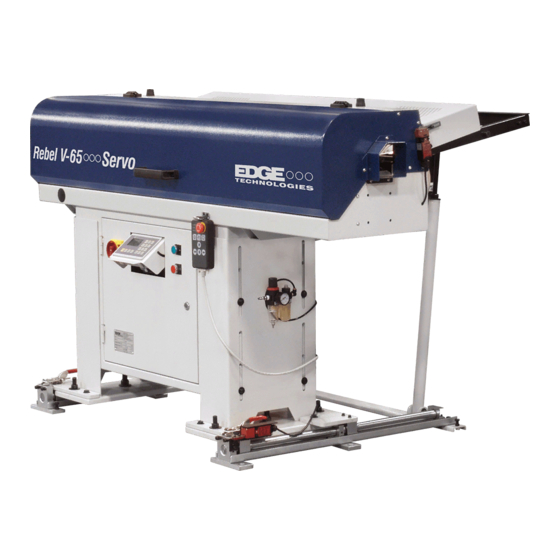
2. DATA OF TECHNIQUE V-65E-A DATA OF TECHNIQUE Introduction of the bar feeder The V-65E/LE-A is designed for full automatic lathe to auto feeds material, the bar feeder is suitable for digital control sliding headstock lathe and fixed headstock lathe. The program of the P.L.C system can control the bar feeder running with the lathe at the same time. -
Page 8: Machine Size
2. DATA OF TECHNIQUE V-65E-A Machine size Description V-65E-A V-65LE-A ∅ 5 mm ~ ∅ 65 mm Diameter of bar max.1250 mm max. 1550 mm Length of bar Bar length depends on Bar length depends on spindle length. spindle length. Spindle height 850 mm ~ 1250 mm Extend spindle height... -
Page 9: Compressed Air Supply And Power Supply
2. DATA OF TECHNIQUE V-65E-A Compressed air supply and power supply 2.4.1 Compressed air pipe minimum Ø 8mm. Minimum pressure 6 kg/cm . Compressed air consumption about 50L/H. 2.4.2 Put the air supply tube into (A). Then pull and turn around the knob (B) and set the pressure at 6kg/cm 2.4.3 Power supply 220V/380V,50/60Hz. -
Page 10: Transportation
3. TRANSPORTATION V-65E-A TRANSPORTATION Hazard- - - - warning: : : : Transportation and hoist (please refer to the item 3.2.1 of following weight table) You have to sure the crane; forklift or other related tools could take the weight. Using the proper equipment to move and hoist the machine should be led by the expert personnel. -
Page 11: Transportation And Hoist
3. TRANSPORTATION V-65E-A Transportation and hoist 3.2.1 Unpacking hoist Putting two steel bars (Diameter: 30mm, Length: 1M) under the bar feeder, using suitable steel ropes which are able to bear the weight to hoist the bar feeder. V-65E-A 250kg(NET) 300kg V-65LE-A 280kg(NET) 370kg... -
Page 12: Forklift Transportation
3. TRANSPORTATION V-65E-A Forklift transportation 3.3.1 Safety regulation moved by forklift 1. The operator of forklift should have been trained. 2. Select the suitable forklift. 3. Make sure the weight and the center of gravity of the machine. 4. The forks should extend under the full length of the machine body during transportation. - Page 13 3. TRANSPORTATION V-65E-A (2) On board transportation (3) Wooden transportation Machine weight approx.:V-65E-A------ 300kg (660lbs) V-65LE-A---- 370kg (814lbs) Moved by crane B. Moved by forklift...
-
Page 14: Installation Area
3. TRANSPORTATION V-65E-A Installation area In order to fix the feeder securely, the floor must be flat and firm. According to the operation of the feeder to reserve a suitable area in advance. Area:(D-operator area),(E-supply area),The space must be enough to avoid the feeder caused crashed by the operator. -
Page 15: Installation
4. INSTALLATION V-65E-A INSTALLATION Bar feeder - - - - Installation Before installing the bar feeder, the spindle of the lathe must be horizontal and the Lathe is fixed on the ground strongly. Adjustment of height 4.2.1 Disengage the screw(1). 4.2.2 Adjust the screw(2)and shift from up to down. -
Page 16: Initial Position
4. INSTALLATION V-65E-A Initial position 4.3.1 Distance between V-65E/LE-A and CNC-lathe In order to use the automatic bar feeder in the best possible way you should see to it that the distance between the CNC-lathe and the bar feeder is not too short!! You may;... -
Page 17: Directional Adjusting
4. INSTALLATION V-65E-A 4.4 Directional adjusting ! IMPORTANT ! During directional adjusting the push bar must not touch the lathe spindle!! The height must have been adjusted roughly beforehand and has to be readjusted if necessary. The direction has to be adjusted rather exactly as the adjusting range for precision adjusting is limited. -
Page 18: Mounting Of The Feeder Frame
4. INSTALLATION V-65E-A Mounting of the feeder frame 4.5.1 First, put the lever into support tube(1). 4.5.2 The support profile fixed with the extension(2)and fastened in the suitable height with screw(3). 4.5.3 Then the middle support profile fixed with the extension(4). 4.5.4 Finally securing with the screw(5). -
Page 19: Accessories Installation
4. INSTALLATION V-65E-A Accessories installation 4.7.1 Axial displacement (optional) 4.7.1.1 Place two woods (height: about 10cm) under the bar feeder. 4.7.1.2 Place axial displacement by each side under stands of the bar feeder (axial displacement has two parts: right part and left part) 4.7.1.3 Push the stands to the end of axial displacement and fix. - Page 20 4. INSTALLATION V-65E-A 4.7.4 Spindle liners 4.7.4.1 How to select correct spindle liners: The inner diameter of the spindle has to be adjusted to the outer diameter of the bar stock. According to our experience, the diameter of spindle of blank bar stock should be bigger by 3mm to 5mm than the diameter of bar stock.
-
Page 21: Adjustments And Setting
5. ADJUSTMENT AND SETTING V-65E-A ADJUSTMENTS AND SETTING Structure of the bar feeder... -
Page 22: Adjustment And Selection Of The Bar Feeder
5. ADJUSTMENT AND SETTING V-65E-A Adjustment and selection of the bar feeder 5.2.1 Adjustment of lever system 5.2.1.1 The inclination of the feeding frame depends on the kind of bar stock used: round bar stock:α about 5˚ ~ 8˚ hexagonal bar stock:α about 20˚ Disengage screw ( 1 ) and ( 2 ). -
Page 23: Adjustment Of Bar Diameter
5. ADJUSTMENT AND SETTING V-65E-A Adjustment of bar diameter 5.4.1 Turn to the manual position , and press until it is lighted. 5.4.2 Swing the handle ( 2 ) to adjust the graduation as same as the diameter of bar on a graduated meter ( 3 ). 5.4.3 Screw tightly the fixing-handle ( 1 ) on both sides. -
Page 24: Selection Of Push Bar
5. ADJUSTMENT AND SETTING V-65E-A Selection of push bar: The push bar has to be adjusted to the bar diameter : Push bar Bar stock ø6mm to ø15mm ø12mm ø15-25mm ø20mm from ø25mm Changing of push bar : ※ remove headless PIN 2 from borne bushing ; ※... -
Page 25: Optimizing Remnant
5. ADJUSTMENT AND SETTING V-65E-A Optimizing remnant By observing the following items the remnant length will be reduced to a minimum: 5.7.1 ※ Exact adjustment of bar end. 5.7.2 ※ Machining and cutting off very close to chuck. 5.7.3 ※ Optimum breaking down of long bars. Optimum breaking down: A ……... -
Page 26: Maintain Notice-Key Switch
5. ADJUSTMENT AND SETTING V-65E-A Maintain notice-key switch 5.8.1 If the safety cover is open, the bar feeder can’t use the automatic mode, but it still can be use manual mode. (1) Need to use the automatic mode when the safety cover is open. Please turn the key-switch to “OFF”. -
Page 27: Operations And Illustrations
6. OPERATIONS AND ILLUSTRATIONS V-65E-A 6. OPERATIONS AND ILLUSTRATIONS 6.1 Material preparation Caution & prevention Please don’t put the material out of standard. List1-The max length of material Type Max length mm 1250 V-65E-A 1600 Bar length depends on spindle length. 1550 V-65LE-A 1900... -
Page 28: Operation Description
6. OPERATIONS AND ILLUSTRATIONS V-65E-A 6.2 Operation description 6.2.1 H/M function description Function LCD Display area Shift Function Number Enter Run light Power light... - Page 29 6. OPERATIONS AND ILLUSTRATIONS V-65E-A 6.2.1.1 Monitor function description: : : : Shift–display:Press the key according to the indication on the display. (1) :Page up (2) :Page down (3) :Back main contents 6.2.1.2 Set up an input for numbers: : : : (1)...
- Page 30 6. OPERATIONS AND ILLUSTRATIONS V-65E-A 6.2.2 The function and operation of keys 6.2.2.1 Description of button and indication light Code Function Code Function Emergency stop LDS3 Clamping in light Start light Manual clamping in/out Chuck open light LDS2 +Z light(left) Alarm light -Z Key Bar end light...
- Page 31 6. OPERATIONS AND ILLUSTRATIONS V-65E-A 6.2.3 Description of operation: : : : Manual operation: Turn to the manual position ; the following 4 keys can start operating. Select Auto start-point: No material in the spindle: When is lightened, it is under manual mode. At this time please press until original point of push bar to lighten, press loading a new bar to V channel.
- Page 32 6. OPERATIONS AND ILLUSTRATIONS V-65E-A 6.2.4 Working cycle- - - - CNC lathe...
-
Page 33: Description Of Settings And Parameter
6. OPERATIONS AND ILLUSTRATIONS V-65E-A 6.3 Description of settings and parameter 6.3.1 HMI Program selection Press the key: : : : Press the key: : : : Press the key: : : : Press the key: : : : Press the key: : : : Press the key:... - Page 34 6. OPERATIONS AND ILLUSTRATIONS V-65E-A 6.3.2 Parameter picture driftage...
- Page 35 6. OPERATIONS AND ILLUSTRATIONS V-65E-A...
- Page 36 6. OPERATIONS AND ILLUSTRATIONS V-65E-A 6-10...
- Page 37 6. OPERATIONS AND ILLUSTRATIONS V-65E-A 6.3.3 Description of settings and parameter 6.3.3.1 Turning parameter Parameter description:This monitor can watch present working status at any time. Watch item︰ 1︰Push bar present position. 2︰Remain effective working length of material. 3︰Remain to wait for working quantities of work piece.
- Page 38 6. OPERATIONS AND ILLUSTRATIONS V-65E-A Parameter description︰This parameter setting will let feed material more stable and ensure the material to be sent to request location. But if no need to use this function that you can set it to be “0” directly. Setting method︰...
- Page 39 6. OPERATIONS AND ILLUSTRATIONS V-65E-A 6.3.3.2 Fixed parameter / enter password“258” Parameter description︰In order to prevent the material be pushed backward by the chuck while the chuck is closed and cause the material too short. Therefore, setting the parameter to delay the time of push bar retreat, but the time can’t be set too long, or else when the chuck be closed and spindle began to rotate, the chuck will crash with the push bar,...
- Page 40 6. OPERATIONS AND ILLUSTRATIONS V-65E-A Parameter description︰This position is the maximum working limit. If pusher position value is bigger than bar end setting that bar feeder will offer a bar end signal to notice lathe to prepare loading new bar material Setting Mode for fixed lathe︰In the manual mode let pusher into lathe spindle until 5~10mm before lathe chuck .
- Page 41 6. OPERATIONS AND ILLUSTRATIONS V-65E-A Parameter description:Chuck facing position is the distance between cutters facing detection to cutter facing position. We cannot know if the new bar material has been pushed to chuck facing position until loading a new bar material. Setting method:...
- Page 42 6. OPERATIONS AND ILLUSTRATIONS V-65E-A Parameter description:This distance is the position that bar pusher pushes out the remnant into the lathe. Setting method: Push the pusher to exceed chuck position 20mm by manual operation. Then confirm the value showing in monitor and input this value. Ex︰...
- Page 43 6. OPERATIONS AND ILLUSTRATIONS V-65E-A Parameter description︰If the pusher cannot push the new bar material to chuck facing position because it is blocked or other reasons that the pusher will have inching movement. But if it exceeds setting frequency that bar feeder will Alarm. Setting method︰...
- Page 44 6. OPERATIONS AND ILLUSTRATIONS V-65E-A 6.3.3.3 System function / enter password“258” Parameter description︰This function according to the necessaries of the operator provides selections to them. “Continue machining” means the quantity of a new material can be machined over one piece. But if a new material can be machined to one piece only, which named “One Piece Machining”.
- Page 45 6. OPERATIONS AND ILLUSTRATIONS V-65E-A 6.3.3.4 Particular program modify / enter password “258” Parameter description︰This function can shift the bar feeder connect with the lathe or auto test. 1.2M Generally value: Setting range : 1.5M Generally value: Setting value : Parameter description︰This function can shift the Logo on the screen of the man machine.
- Page 46 6. OPERATIONS AND ILLUSTRATIONS V-65E-A Parameter description︰This is the bar feeder required a start signal to send the sequence for CNC program, relative to the description of sequence, please refer to the description of sequence of movement signal in article 6.2.3. 1.2M Generally value:...
- Page 47 6. OPERATIONS AND ILLUSTRATIONS V-65E-A Parameter description︰The lathe gives a feeding signal to the bar feeder are two modes: 1. Chuck Signal 2. M-Code. If the interface of lathe and bar feeder only connect “Chuck Signal”, please set for “0: M-Code No Use”.
- Page 48 6. OPERATIONS AND ILLUSTRATIONS V-65E-A Parameter description︰This parameter allow technician to test each signal output on interface is continued to lathe. Setting method︰ To executive this parameter must be under manual mode both lathe and bar feeder or could cause danger.
-
Page 49: Refer Alarm Message
6. OPERATIONS AND ILLUSTRATIONS V-65E-A 6.4 Refer alarm message 6.4.1 HMI Alarm Message ERROR / CAUSE CURE ※ Please check the value of long feed safety is correct ※ Check the turret whether at correct position of stopping material ※ Please check the value of short feed safety is correct ※... - Page 50 6. OPERATIONS AND ILLUSTRATIONS V-65E-A ERROR / CAUSE CURE ※ Please refer to electrical diagram (P.01) , LS5 is operative while SS1 is opened. ※ Please push the bar feeder to correct position of working. ※ Check the pressure of the compressed air. ※...
Need help?
Do you have a question about the V-65 Series and is the answer not in the manual?
Questions and answers