
Related Manuals for York YB


Summary of Contents for York YB
- Page 1 CONTROL CENTER CENTRIFUGAL LIQUID CHILLERS OPERATION MANUAL Supersedes: Nothing Form 160.60-O2 (1004) FLEXLOGIX CONTROL CENTER MODEL YB & YG GAS ENGINE LIQUID CHILLER Design Level B...
- Page 2 All wir ing must be in ac cor dance with YORK’s pub lished spec i Þ ca tions and must be per formed ONLY by qual i fied YORK personnel. YORK will not be re spon si ble for dam ag es/problems re sult ing from im prop er con nec tions to the con trols or ap pli ca tion of im prop er con trol sig nals.
- Page 3 YORK Applied equipment has been modifi ed and if current lit er a ture Systems Service offi...
-
Page 4: Table Of Contents
SAH-160A “ENGINE OVERSPEED” ......38 CORRECTING ALARMS AND SYSTEM TRIPS ..... 42 PAL-160 “ENGINE LOW OIL PRESSURE” ....38 SI METRIC CONVERSION ..........44 ZAL-140 “COMPRESSOR PROX FORWARD TEMPERATURE.............. 44 (J-SERIES ONLY)” ............38 INDEX...............45 ZAL-140 “COMPRESSOR PROX REVERSE (J-SERIES ONLY)” ............38 YORK INTERNATIONAL... - Page 5 FIG. 23 – ALARM POPUP BOX SHOT ......36 (BOTH INPUTS HIGH)” ..........40 FIG. 24 – HISTORY SCREEN ........37 “VS OIL PUMP DIDN’T START”........40 “POWER FAILURE” ............40 “PROGRAM FAULT” ...........40 “PURGE ENGINE IN MAINTENANCE MODE”..40 “ PROXIMITOR ZE-140 UNCALIBRATED (J-SERIES COMPRESSORS ONLY)” ......40 YORK INTERNATIONAL...
-
Page 6: Section 1 - Description Of System And Fundamentals Of Operation
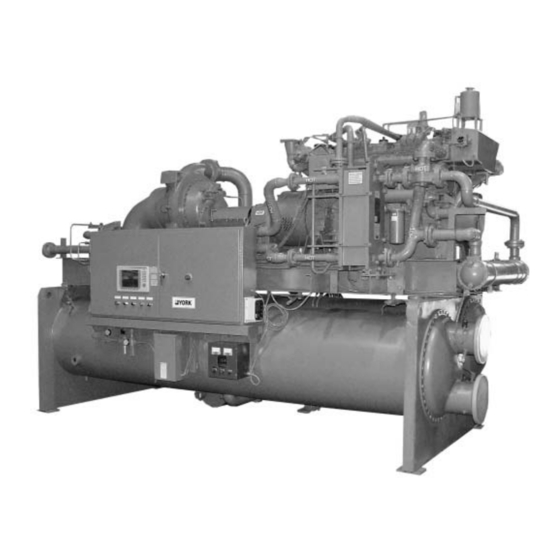
FIG. 1 – MODEL YG GAS ENGINE CHILLER GENERAL SYSTEM DESCRIPTION SYSTEM OPERATION The YORK Model YG Gas Engine Chiller is commonly In operation, liquid water fl ows through the evaporator applied to large air conditioning systems, but may be where boiling refrigerant absorbs heat from the water. -
Page 7: Capacity Controls
During part-load operation at off-design conditions, the chiller capacity is reduced to maintain a constant leaving chilled liquid temperature by fi rst decreasing the speed and closing the compressor pre-rotation vanes ( PRV) (See Detail A), then opening the hot gas bypass valve. YORK INTERNATIONAL... -
Page 8: Refrigerant Flow Diagram
HIGH PRESSURE LIQUID REFIGERANT COMPRESSOR LOW PRESSURE LIQUID REFIGERANT LOW PRESSURE VAPOR DISCHARGE HOT GAS BYPASS VALVE CONDENSER SUCTION ELIMINATOR SUB-COOLER EVAPORATOR LEVEL CONTROL LIQUID LEVEL REFRIGERANT VALVE SENSOR DRAIN AND CHARGING FIG. 2 – REFRIGERANT FLOW-THRU CHILLER YORK INTERNATIONAL... - Page 9 FORM 160.60-O2 (1004) This page intentionally left blank. YORK INTERNATIONAL...
-
Page 10: Section 2 - Panelview Plus 1000 Control Center Introduction
The locations of various chiller parameters are source and system access level. (See below) clearly marked and instructions for specifi c operation are provided on many of the screens. YORK INTERNATIONAL... -
Page 11: Interactive Screen Features
The chiller Control System has four access levels: VIEW, OPERATOR, SERVICE and SUPER USER. This instruction is intended only as an operator manual. As such, depicted here are the system parameters available at the VIEW and OPERATOR LD09906 YORK INTERNATIONAL... -
Page 12: Home Screen
Displays the temperature of the liquid leaving the condenser PRV Position Displays the position of the pre-rotation vanes in percent Engine Speed Displays the engine speed in RPM Condenser Flow Switch Indicates that liquid is fl owing through the condenser YORK INTERNATIONAL... -
Page 13: System Screen
Oil Sump Temperature Displays the temperature of the oil in the compressor oil sump Oil Supply Pressure Displays the pressure of the compressor oil system Chilled Liquid Temperature Entering/Leaving YORK INTERNATIONAL... -
Page 14: Evaporator Screen
Displays the pressure and temperature of the evaporator refrigerant (K8) Network Setpoints Selecting this tab toggles between hardwire and network Remote Setpoint chilled water setpoint Displays the remotely set chilled water setpoint Evaporator Flow Switch Indicates that chilled liquid is fl owing through the evaporator YORK INTERNATIONAL... -
Page 15: Condenser Screen
(F3) Subcooler Level Setpoint Condenser Small Temperature Difference Allows the operator to adjust the subcooler refrigerant Displays the temperature expressed as the differential level setpoint between the water entering and the water leaving the condenser YORK INTERNATIONAL... -
Page 16: Subcooler Screen
Condenser Small Temperature Difference Displays the temperature expressed as a differential temperature between the water leaving and the water entering the condenser Evaporator Refrigerant Level (Graphical) Displays the evaporator refrigerant level in percent YORK INTERNATIONAL... -
Page 17: Compressor Screen
Oil Pump Frequency Displays the operating frequency of the variable-speed oil pump drive PRV Motor Opening/Closing Indicates the status of the pre-rotation vane actuator PRV Position Displays the position of the pre-rotation vanes in percent YORK INTERNATIONAL... -
Page 18: Oil Sump Screen
Oil Supply Pressure Displays the oil supply pressure Oil Pump Frequency Displays the variable-speed oil pump drive frequency Oil Pump Run Indicates the operational status of the oil pump Oil Return Solenoid Indicates the status of the oil return solenoid YORK INTERNATIONAL... -
Page 19: Pre-Rotation Vanes Calibration Screen
For manual calibration of the PRV; corresponds to the raw PRV potentiometer input with the vanes fully closed Span Value For manual calibration of the PRV; corresponds to the raw PRV potentiometer input with the vanes fully open YORK INTERNATIONAL... -
Page 20: Hot Gas Valve Screen
Compressor Head Displays the pressure expressed as a differential between the compressor suction and compressor discharge pressures Valve Position Displays the position of the valve in terms of percentage open YORK INTERNATIONAL... -
Page 21: Gearbox Screen
Indicates the status of the low oil pressure trip switch Gear High Oil Temperature Trip Switch Indicates that status of the high gear oil temperature trip switch Gear Oil Pump Indicates the operational status of the gear oil pump Engine Run Indicates operation of the engine YORK INTERNATIONAL... -
Page 22: Engine Screen
Displays engine rpm to the main panel to terminate engine crank Water Jacket Temperature (Graphical) Water Jacket Temperature Signal Displays the water jacket temperature in º F Indicates whether or not the water jacket temperature has exceeded safe limits YORK INTERNATIONAL... - Page 23 Indicates whether or not the engine is in an overspeed condition Engine Emergency Stop Signal Indicates that the emergency stop switch on the engine panel has been depressed Engine Water Level Signal Indicates whether or not the engine water level is within safe limits YORK INTERNATIONAL...
-
Page 24: Load Curve Screen
Do not modify manifold pressure entries without factory consultation DISPLAY Intake Manifold Pressure Displays the current engine intake manifold pressure Percent Load Curves (Graphical) Displays the engine load based on manifold pressure and rpm in percent YORK INTERNATIONAL... -
Page 25: Capacity Controls Screen
Displays the system low evaporator pressure setpoint PRV Target Condenser Pressure Displays the control-system intended position of the Displays the current condenser pressure pre-rotation vanes High Pressure Setpoint Displays the system high condenser pressure setpoint Engine Load Displays the current engine load YORK INTERNATIONAL... - Page 26 PRV position setpoints PRV Ramp Displays the ramp rate signal strength in percent TEMPERATURE CONTROL Leaving Chilled Liquid Setpoint Displays the current chilled liquid temperature Setpoint Current manual, automatic, remote, or network remote chilled liquid setpoint YORK INTERNATIONAL...
-
Page 27: Manual/Auto Station (Capacity Controls)
Manually adjust the Hot Gas Valve INTERACTIVE to match the automatic setting before (F1) Hot Gas Valve re-engaging automatic control. Allows the operator to manually adjust the position of the hot gas valve from fully open to fully closed YORK INTERNATIONAL... -
Page 28: Trending Screen
The F5 and F7 keys move along the horizontal scale of the graph, which depicts time in fi ve-minute increments. The F8 function key toggles the trace on or off. Pens are color coded for clarity. YORK INTERNATIONAL... -
Page 29: Pid Tuning Screen (Capacity Controls)
LOC SP Process variable; actual compressor discharge pressure Local chilled water setpoint; also available on the in psig Evaporator Screen. Output Output Control variable output signal from 0 to 100% Control variable output signal from 0 to 100% YORK INTERNATIONAL... - Page 30 PRV Response Gain: 4800 LOW PRESSURE OVERRIDE Setpoint: 28.0 psig P: 1.000 I: 2.000 D: 0.000 ENGINE LOAD LIMITER Setpoint: 100.0 P: 0.800 I: 1.500 D: 0.000 HIGH PRESSURE OVERRIDE Setpoint: 175.0 P: 1.000 I: 2.000 D: 0.005 YORK INTERNATIONAL...
-
Page 31: Anti-Surge Tuning Screen
SPD2 is the minimum system head pressure as defi ned 1500 rpm by the entry fi elds below the Surge Map. (MSP2) Minimum Engine Speed @ Minimum Sys- tem Head MSP1 is the minimum allowable anti-surge speed at the 1400 rpm maximum system head pressure, SPD1 YORK INTERNATIONAL... -
Page 32: Section 3 - System Operating Procedures
→ HOT GAS. The valve position idle speed, whichever happens fi rst. graphic should indicate that the hot System Status indication: Engine Start Initiated gas bypass valve is fully open. YORK INTERNATIONAL... -
Page 33: Normal Shutdown
The Control System will then initiate are System Status indication: Chiller Off normal system shutdown. Manual Shutdown (Emergency) In the event that the emergency stop button on either the main panel or engine panel is activated, the system YORK INTERNATIONAL... -
Page 34: Section 4 - System Status Display Messages
“ SYSTEM RUNNING” slowing to allow proper cooling before shutdown. Once the engine has fi nished warm-up and ramped to operating speed, the clutch engages and the chiller begins to operate. YORK INTERNATIONAL... -
Page 35: Engine Purge
“ENGINE MAINTENANCE RUN” When the engine maintenance run is initiated, the driveline is disabled. “CHILLER OFF” The system may be switched off to prevent automatic operation. YORK INTERNATIONAL... -
Page 36: Section 5 - Alarm And Trip Messages
(F3) Silence Alarms What follows is a listing of possible trip and alarm Causes alarm to be silenced until the system detects messages and their meanings. another alarm FIG. 23 - ALARM POPUP BOX SHOT LD09894 YORK INTERNATIONAL... -
Page 37: Alarm Messages
If the engine emergency stop switch is activated, the PARAMETERS” system alerts the operator that the engine needs to be If the PD1, PD2, MSP1 or MSP2 values are entered out purged in order to safely restart. of fi eld, the alarm is triggered. YORK INTERNATIONAL... -
Page 38: Tah-140 "High Sump Oil Temperature
If the engine oil pressure drops below safe limits, the The clutch pressure switch has two states: open and alarm is triggered. closed. If the system logic detects two simultaneous signals, a switch malfunction is indicated and the system will fall off line. YORK INTERNATIONAL... -
Page 39: Ps-151 "Clutch Failed To Disengage
TEMPERATURE” PRESSURE” This trip corresponds to an engine overheat condition. This trip indicates compressor oil pressure above safe limits. TSLL-161 “ENGINE LOW OIL PRESSURE” If the engine oil pressure drops below 40 psig, the system trips off line. YORK INTERNATIONAL... -
Page 40: Tahh-140 "High Sump Oil Temperature
If the engine cooling water level in the water “ VS OIL PUMP DIDN’T START” jacket drops below allowable limits, the system will If the variable speed oil pump motor faults, the system trip off line. trips off line. YORK INTERNATIONAL... -
Page 41: Engine Running No Speed Pickup Signal
If the starter motor cranks for 30 seconds continuously, it requires a two-minute cooldown period before it can be run again. If the motor is resting and a restart is attempted, the system signals a trip off line. YORK INTERNATIONAL... -
Page 42: Section 6 - Restarting The Chiller After System Trip
Other alarms and system trips may occur during operation, and the engine will need to be purged before a restart can be attempted. YORK INTERNATIONAL... - Page 43 FORM 160.60-O2 (1004) YORK INTERNATIONAL...
-
Page 44: Metric Conversion
To convert degrees Fahrenheit (°F) to degrees Celsius (°C), subtract 32° and multiply by 5/9 or 0.5556. To convert a temperature range (i.e., 10°F or 12°F chilled water range) from Fahrenheit to Celsius, multiply by 5/9 or 0.5556. YORK INTERNATIONAL... -
Page 45: Index
Executing an Engine Purge 42 Discharge Pressure 29 High Water Jacket Temperature 39 Head 13,17,20,27 Ignition Enable 32 Oil Pressure 37,38,39,40 Load 25 Pre-lube 32 Load Limiter 29,30 Prox Forward 38,39 Low Oil Pressure 38,39 Prox Reverse 38,39 YORK INTERNATIONAL... - Page 46 Small Temperature Difference 14 Low Pressure Override 29,30 Temperature (Saturation) 13 Low Pressure Setpoint 25 Executing an Engine Purge 42 Low Sump Oil Temperature 37,40 Function Keys 11,27 Main Screen 11 manifold pressure 22,24 Gear Manual/auto Station (Capacity Controls) Screen 27 YORK INTERNATIONAL...
- Page 47 Pre-rotation Vanes 17, 27 VS Oil Pump 40 R1 Hardwire 38 Ramping to Minimum Speed 34 Ramp to Minimum Speed 33 Water Jacket 22,40 Remote Lockout 34 Water Jacket Temperature 22,25 Remote Start Denied 37 Water Jacket Temperature Signal 22 YORK INTERNATIONAL...
- Page 48 Tele. 800-861-1001 P.O. Box 1592, York, Pennsylvania USA 17405-1592 Subject to change without notice. Printed in USA Copyright © by York International Corporation 2004 www.york.com ALL RIGHTS RESERVED Form 160.60-O2 (1004) Supersedes: Nothing...
Need help?
Do you have a question about the YB and is the answer not in the manual?
Questions and answers