
Related Manuals for KEENCUT PROTEUS


Summary of Contents for KEENCUT PROTEUS
- Page 1 PROTEUS PROTEUS PROTEUS PROTEUS PROTEUS PROTEUS PROTEUS PROTEUS The key to a superb workplace Assembly instructions...
-
Page 2: General Guidelines
This feature allows the key to be rotated fully when used in a confined area. Many ratchet screw driver tool sets contain 5mm Allen key bits which can be very useful when assembling the Proteus. -
Page 3: Construction Details
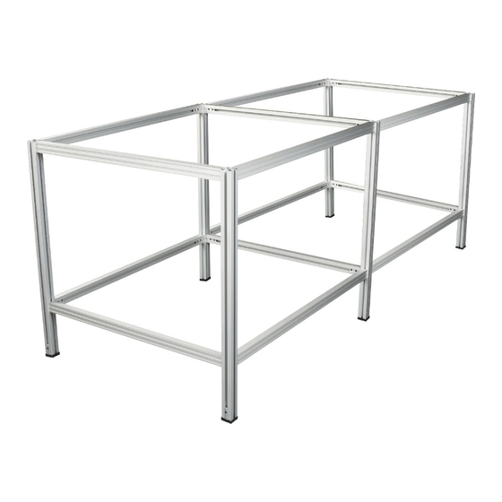
SPECIAL ASSEMBLY NOTES AND PRECAUTIONS Both the beam and leg sections feature special webs which are intended to collapse locally under pressure from the conical end of the grub screw . The result is a permanent and secure position for each grub screw which is designed to prevent collapse of a structure under load in the event of one or more grub screws working loose over a period of time. - Page 4 Workbench or Table SECTION 1 You should have : ITEM ITEM Grub Screw Joining Long Beam Bracket Short Beam Screw Work Top Clip TOOLS ITEM Allen Key Leg-End Cap Spacer Put a grub screw backwards into each of the joining brackets - do not place grub screws in the other holes at this stage.
- Page 5 (Continued) We will assume for the purposes of these instructions, that the style on the left is required. Using the spacer , fit two brackets to the top of each leg ensuring the brackets are fitted the correct way round - with the flat faces towards each other.
- Page 6 Join the end frames Place one end frame on the floor with the brackets pointing upwards, position a long beam over each bracket , ensuring the small groove in the beam is uppermost. Place the other end frame over the beams and tighten the grub screws ensuring there are no gaps between the beam end and the legs .
- Page 7 Single Matboard Storage Unit SECTION 3 If you are assembling an extension unit with a standard unit – NOTE: go to section 5 You should have : ITEM PD02 PD07 ITEM PD02 PD07 Base Channel Grub Screw Joining Dividing Rod Bracket Fixing Channel Screw...
- Page 8 Using the spacer , fit two brackets to the top of each leg ensuring the brackets are fitted the correct way round - with the flat faces towards each other. ✘ ✓ Attach joining brackets to the bottom of the legs , again using the spacer, position them as shown.
- Page 9 Repeat for the RH frame. Remember to ensure the groove in the beam is on top. R.H. FRAME BOTTOM Join the end frames Position the beams (set of 3) on the end frames as shown, again ensuring the groove in the beam is at the top. Tighten the grub screws ensuring there are no gaps between the beam ends and the legs.
- Page 10 Fitting the base channels Place the unit in its final position, once the base channels are fitted the unit can be dragged but not lifted. Slide the base channels in place starting from the outside working towards the centre. Ensure the set of holes in the edges are towards the front of the unit.
- Page 11 SECTION 4 Adding a Matboard Storage Unit Extension If you are assembling an Matboard Storage unit with an extension unit NOTE: – – go to section 5 You should have : ITEM PR02 PR07 ITEM PR02 PR07 Grub Screw Base Channel Joining Dividing Rod Bracket...
- Page 12 Attach the Joining brackets to the legs BACK LEG FRONT LEG Using the spacer , fit the joining brackets to the top of each leg NOTE:- Ensure the joining brackets are fitted the correct way round. Put grub screws in each of the two large holes in every bracket , only screw them in by 2 or 3 turns.
- Page 13 (Continued) Release the grub screws to remove the end frame and replace it with the centre frame. NOTE:- Rod supports are not show for clarity. Complete the frame work Using the set of 3 beams assemble the unit as shown. Ensure all grub screws are tightened fully and there are no gaps between the beam ends and legs .
- Page 14 Fitting the base channels Slide the base channels in place starting from the outside working towards the centre. Ensure the set of holes in the edges are towards the front of the unit. The two channels on the outside fit tight to the inside of the beam leaving a small gap at the back of the channel.
- Page 15 SECTION 5 Matboard Storage Unit with Extension NOTE: If you are adding an extension to an existing Matboard Storage Unit – go to section 4. For a Parts List refer to the beginning of: Section 3 – Matboard Storage unit PD02 & PD07 Section 4 –...
- Page 16 (Continued) BACK LEG FRONT LEG Using the spacer , fit the joining brackets to the other two leg s as shown, these will make the centre frame . NOTE:- Ensure the joining brackets are fitted the correct way round. Put grub screws in each of the two large holes in every bracket , only screw them in by 2 or 3 turns.
- Page 17 Make the Centre frame FRONT LEG Assemble the frame using the beam with holes and the other single beam of the same length. ensure the beam with holes is assembled the correct way round ( see diagram ) HOLES TOWARDS Tighten all the grub screws using the long end of the allen key .
- Page 18 Fitting the base channels Slide the base channels in place starting from the outside working towards the centre. Ensure the set of holes in the edges are towards the front of the unit. The two channels on the outside fit tight to the inside of the beam leaving a small gap at the back of the channel.
- Page 19 Covering the worktop with fabric SECTION 6 Worktops can be covered with many types of worksurface, the Proteus covering (PN01/2/3) is a grey non woven fabric which will not fray or unravel and can be moulded around worktop corners. Proteus worktop fabric has a smooth upper surface and slightly rougher underside to key into adhesives. Use double sided carpet tape, carpet/flooring adhesive or staples.
- Page 20 Fitting the Worktop SECTION 7 It is advisable to fit one piece worktops cut from 18mm ( ”) MDF. When deciding on the size of your worktop make allowances for any overhangs you require. The worktop clips are hooked into the slot on the inside of the beam and screwed into the underside of the worktop.
- Page 21 SECTION 8 Fitting Cantilever Matcutter Supports You should have : ITEM ITEM Beam Grub Screw Rubber Pad Joining Bracket Beam End Cap TOOLS ITEM Allen Key Put a grub screw backwards into each of the joining brackets - do not place grub screws in the other holes at this stage.
Need help?
Do you have a question about the PROTEUS and is the answer not in the manual?
Questions and answers