Table of Contents
Advertisement
Thank you for purchasing this Esco Low Temperature BOD
Incubator. Please read this manual thoroughly to familiarize
yourself with the many unique features and exciting
innovations we have built into your new equipment. Esco
provides many other resources at our website,
www.escoglobal.com, to complement this manual and help you
enjoy many years of productive and safe use of your Esco
products.
Esco Technologies, Inc.
2940 Turnpike Drive, Units 15-16 • Hatboro, PA 19040, USA
Toll-Free USA and Canada 888-375-ESCO
Tel 215-441-9661 • Fax 215-441-9660
us.escoglobal.com • usa@escoglobal.com
Esco Micro Pte. Ltd.
21 Changi South Street 1 • Singapore 486 777
Tel +65 6542 0833 • Fax +65 6542 6920
www.escoglobal.com • mail@escoglobal.com
User
Manual
Isotherm
Advertisement
Table of Contents

Related Manuals for Esco Isotherm IFC-110-8


Summary of Contents for Esco Isotherm IFC-110-8
- Page 1 Esco provides many other resources at our website, www.escoglobal.com, to complement this manual and help you enjoy many years of productive and safe use of your Esco products. User Manual Esco Technologies, Inc.
- Page 2 Esco makes no representations or warranties as to the accuracy of the information contained in this manual. In no event shall Esco be held liable for any damages, direct or consequential, arising out of or related to the use of this manual.”...
-
Page 3: Table Of Contents
Table of Contents Warranty Terms and Conditions Introduction 1. Products Covered 2. Safety Warning 3. Limitation of Liability 4. European Union Directives on WEEE and RoHS Declaration of Conformity Chapter 1 – Product Information 1.1 About Isotherm Low Temperature BOD Incubator 1.2 Labels 1.3 Quick View 1.3.1 Front Quick View... - Page 4 4.2.3 Bottom panel 4.2.4 Work Zone Decontamination 4.3 Physical Inspection 4.3.1 Re-Adjustment of Outer Door 4.4 Removal of Deposits 4.5 UV Lamp Replacement 4.6 Maintenance/Service Logs Chapter 5 – Troubleshooting Appendix Isotherm...
- Page 5 Esco that these parts were defective at the time of being sold, and that all defective parts shall be returned, properly identified with a Return Authorization.
- Page 6 3 years limited. 60 months on Compressor. The warranty period starts two months from the date your equipment is shipped from Esco facility for international distributors. This allows shipping time so the warranty will go into effect at approximately the same time the equipment is delivered to the user.
-
Page 7: Products Covered
The disposal and / or emission of substances used in connection with this equipment may be governed by various local regulations. Familiarization and compliance with any such regulations are the sole responsibility of the users. Esco’s liability is limited with respect to user compliance with such regulations. 4. European Union Directive on WEEE and RoHS The European Union has issued two directives: •... - Page 8 Isotherm...
- Page 9 Low Voltage : EN 61010-1:2010 : EN 61326-1:2006 Class B More information may be obtained from Esco’s authorized distributors located within the European Union. A list of these parties and their contact information is available on request from Esco _______________________________...
- Page 10 viii Isotherm...
-
Page 11: About Isotherm Low Temperature Bod Incubator
1.1 About Isotherm Low Temperature BOD Incubator Forced Convection Convection is a method to transfer of heat energy that involves the movement of a fluid (gas or liquid). Fluid in contact with the source of heat expands and tends to rise within the bulk of the fluid. Cooler fluid sinks to take its place, setting up convection current. -
Page 12: Quick View
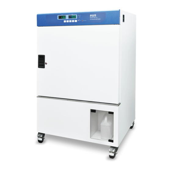
1.3 Quick View 1.3.1 Front Quick View 1. Control panel. 2. Outer door - maintains temperature inside the equipment. 3. Outer door handle. 4. UV lamp switch -controls operation of UV lamp. 5. UV lamp - sterilizes inner chamber and loads. 6. -
Page 13: Back Quick View
1.3.2 Back Quick View 1. Electrical inlet -connects to power supply. 2. Main switch button -turns the equipment ON/OFF. 3. Outer door -maintains temperature inside unit. 4. Outer chamber - protects parts inside. 5. RS485 Port - RS485 connection. 1.4 Applications It is commonly used as Biochemical Oxygen Demand determinations of waste water and sewage (APHA method at 20 Plant cell growth... - Page 14 Isotherm...
-
Page 15: General Requirement
– 2.1 General Requirement 2.1.1 Location Requirements Isotherm Low Temperature BOD Incubator (IFC) must be placed on the solid and level surface. It is important that the equipment is set up accurately horizontally and against abnormal vibration and noise. Door may have to be adjusted. (See Chapter 4 “Maintenance and Cleaning”). Lock the 2 front casters (by pushing down the pedals) to fix position of the equipment. -
Page 16: Power Requirements
Water container 2.3 Disclaimer The performance and safety of the incubator, while rigorously evaluated at the factory, cannot be guaranteed once after transit and installation. Therefore the on-site testing is always recommended. References for qualified Certifiers: Esco Distributor Esco (www.escoglobal.com) Isotherm... -
Page 17: Control System
3.1 Control System Actual Set Point LED Indicator Display Display Function Over Temperature Indicator Keys 3.1.1 Function Keys Enters menu options. MENU Switches between submenus. Enters temperature and time setting option under basic operation mode. SET TEMP Enters submenu/save set parameters and withdraw submenu. Parameter value plus key. -
Page 18: Opening/Closing The Outer Door
3.2.2 Opening/Closing Outer Door Pull-down the handle to open the door, and pull-up to close the door. NOTE: As there are 2 knobs at the top and bottom of the outer door, the outer chamber may be damaged by the knobs if door handle is pulled-up during closing the door. -
Page 19: Menu & Options
There must be sufficient spacing of the load inside the equipment to ensure proper ventilation within the equipment. Do not place any load on the floor, against the side wall or underneath the ceiling of the equipment. In order to ensure optimal ventilation, shelf should be inserted so that air spacing between shelves, door, load and inner chamber wall is approximately equal. -
Page 20: Alarm Setting
3.3.1 Alarm Setting The high point temperature alarm setting can be adjusted. Please note the alarm value is a relative setting. Range for alarm setting: 2°C~10°C (If the refrigeration system is active, use 2 C). In case, actual temperature in equipment is equal or higher than temperature set point + alarm value, buzzer will sound and red light of "Alarm"... -
Page 21: Address Setting
3.3.3.2 Enter PIN Step Description Button Display MENU – Press MENU or SET TEMP button to enter PIN. SET TEMP Press UP/DOWN button to set the PIN’s digit. Press SET TEMP to confirm UP/DOWN – the number and move to the next digit. SET TEMP Repeat step 3 until the fourth digit. -
Page 22: Defrost Setting
3.3.6 Defrost Setting Step Description Button Display Press MENU button until the display shows Setting. Press SET TEMP to MENU – enter the menu. SET TEMP Press MENU button until the display shows Defrost. MENU Press UP/DOWN button to set the defrost timer. Press SET TEMP to save UP/DOWN –... -
Page 23: Scheduled Maintenance
4.1 Scheduled Maintenance Proper and timely maintenance is crucial for trouble free functioning of any device and your Esco unit is no exception to this rule. We strongly recommend that you follow the maintenance schedule suggested here under in order to obtain optimal performance from your unit. -
Page 24: Control Panel, Exterior & Interior Surfaces, Screen Frame, Temperature Probe
Socket screw Part Closing panel Screw NOTE: It must be conducted by qualified electrician or technician authorized by Esco. Cut off power supply before doing maintenance works. It is recommended that the maintenance is done annually. Isotherm... - Page 25 4.4 Removal of deposits Deposits can be removed by three ways, depending on the composition of loads and contacted materials. Automatic high temperature decontamination Note: Take out all combustible materials and set overheat protector to maximum value beforehand. Spray standard acid-free disinfectant Note: Before startup, thoroughly wipe the unit with dry cloth as explosive gases may be generated during pollutant removal.
- Page 26 Isotherm...
- Page 27 Power Distribution Please check first with your electrical engineer certified Board Fuse has Contact ESCO technical service for replace the fuse blown NOTE: It is recommended to disconnect the main power cord from the outlet wall socket when accessing the electrical panel to prevent electric shock.
- Page 28 Problem 5: Overshoot or under shoot temperature Possible Cause Corrective Action Leak on the gasket Paper check : put the paper between glass door and gasket chamber than pull the chamber paper and feels rough If the test is failure please contact technical service Refrigeration Please contact technical service system is failed...
- Page 29 APPENDIX...
- Page 31 Incubator : _______________________________________________________________ Serial Number : _______________________________________________________________ Person in Charge : _______________________________________________________________ 1. This log record should be used by the operator to record any new agent that has been introduced to the freezer during its operation, problems encountered, etc. 2.
Need help?
Do you have a question about the Isotherm IFC-110-8 and is the answer not in the manual?
Questions and answers