Advertisement
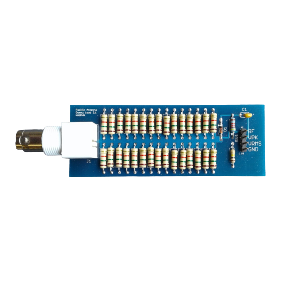
Pacific Antenna 15 Watt Dummy Load Kit
Introduction
Our 10 Watt Dummy Load kit is a compact design using all through hole parts
A great first time kit to learn or improve soldering skills.
Can be assembled with common soldering tools and techniques
Provides direct RF as well as DC voltages representing the Peak and RMS values.
Accurately measures RF Power from less than 100mW to 15 Watts with just a digital Multimeter
Usable from DC to 60MHz
Includes all the components and circuit board.
Inspection and Inventory
First, check the kit to be sure all parts are included. Should anything be missing, please contact us for a
replacement.
30 – R1-R30, 1.5 K 1/2 watt resistors: Brown-Green-Red-Gold
1 – R55: 41.2K 1/4W, 1% resistor: Yellow-Brown-Red-Red-Brown
1 – R56: 100K 1/4W, 1% resistor: Brown-Black-Black-Orange-Gold
1 – D1: 1N4148 diode
1 – C1: 0.01uF monolythic capacitor, yellow, (marked 103)
1 – J1: BNC board mount connector
1 – SV1: 4 pin header
1 – Circuit board
DummyLoad20190402
1
Advertisement
Table of Contents

Related Manuals for Pacific Antenna Dummy Load V2

Summary of Contents for Pacific Antenna Dummy Load V2
- Page 1 Pacific Antenna 15 Watt Dummy Load Kit Introduction Our 10 Watt Dummy Load kit is a compact design using all through hole parts A great first time kit to learn or improve soldering skills. Can be assembled with common soldering tools and techniques Provides direct RF as well as DC voltages representing the Peak and RMS values.
- Page 2 Board Layout Assembly Install R1- R30 These are the 1/2W. 1.5K ohm resistors and they go in the marked locations shown on the circuit board. You may find it helpful to do one row of the resistors at a time to make soldering the leads easier. First, pre-bend the leads near the resistor bodies and then insert them into the board.
- Page 3 Install R55 the 41.2K ohm (Yellow-Brown-Red-Red-Brown) resistor in the marked location on the board Install R56, the 100K resistor (Brown-Black-Black-Orange-Gold) in the marked location on the board. Note: R56 is now a 1% resistor and has a blue body. The photo below shows a 5% resistor for R56. Install C1 the 0.01uF capacitor in the location marked on the board.
- Page 4 Initial test To verify proper soldering, it is recommended to use a multimeter and measure the resistance across the input BNC connector or between the header pin 1 and 4. The value should be close to 50 Ohms. If not, there may be one or more bad solder joints in the resistor array. Operation The dummy load is easy to use.
- Page 5 Schematic Copyright 2016-2019 Pacific Antenna www.qrpkits.com DummyLoad20190402...
Need help?
Do you have a question about the Dummy Load V2 and is the answer not in the manual?
Questions and answers