
Related Manuals for Digitimer DS4

Summary of Contents for Digitimer DS4
- Page 1 Digitimer DS4 Bi-phasic Stimulus Isolator OPERATOR'S MANUAL “Digitimer” is a registered trade mark of Digitimer Limited...
- Page 2 DS4 Bi-phasic Stimulus Isolator DS4 Operator's Manual Issue 1.1 Product Registration Please take time out to register your new product. Details are included in the Introduction. You can even do it online at:- www.digitimer.com/register Digitimer Ltd. 2 of 21 Copyright 2019...
-
Page 3: Table Of Contents
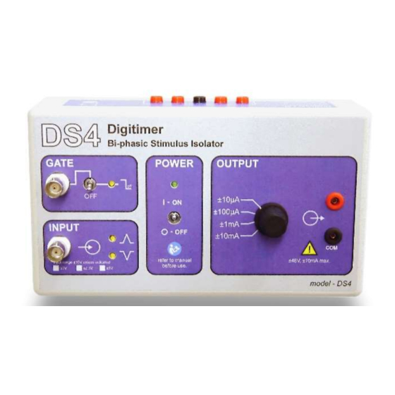
DS4 Bi-phasic Stimulus Isolator DS4 Operator's Manual Issue 1.1 Table of Contents Introduction ......................5 Precautions and Warnings ..................6 Operator’s Manual .................... 6 Explosion and Fire .................... 6 Damage ......................6 Moisture ......................6 Electrical Interference ..................6 Contact Address ....................6 Servicing &... - Page 4 Index of Figures & Tables Figure 1 The DS4 Bi-phasic Stiimulus Isolator.............. 5 Figure 2 Positioning of the DC power supply socket on the DS4........9 Figure 3 The POWER zone of the DS4 front panel............9 Figure 4 The GATE zone of the DS4 front panel.
-
Page 5: Introduction
The DS4 uses a special "inactivity sensor" to monitor the input voltage and disable the DS4 output if this voltage falls below 0.15% of the full scale value (in -ve or +ve directions) for a user selectable time period of 100ms, 200ms, 1s or 2s. Unlike other devices which only produce an output when the input voltage exceeds a threshold value, this "inactivity... -
Page 6: Precautions And Warnings
Servicing & Maintenance This equipment does not require any regular maintenance but if you would like your DS4 to be serviced we are happy to do so. Please contact us for a reference number and instructions before despatching the unit. -
Page 7: Product Registration
This web address is your point of contact for all questions regarding the DS4. The site’s contents are now growing rapidly, so please bookmark it so that you visit it regularly to check out the new items. -
Page 8: Declaration Of Conformity
DS4 Bi-phasic Stimulus Isolator DS4 Operator's Manual Issue 1.1 Declaration of Conformity Digitimer Ltd. 8 of 21 Copyright 2019... -
Page 9: Functions & Features
The DS4 control circuitry is powered by the supplied ±15V DC power supply adaptor which must be connected to the DS4 via the socket illustrated in Figure 2. The supplied mains lead should then be used to connect the DC power supply adaptor to a suitable mains supply (110-220V AC). Once all connections have been made, the mains socket and the DS4 can be switched on. -
Page 10: Gate Zone
Input Zone A command voltage waveform is applied at this BNC socket and is used by the DS4 to determine the shape of the stimulus it delivers. The DS4 accepts various input voltage ranges, but is factory set to ±10V. An internal jumper allows the operator to change the input voltage range to ±1V, ±2.5V or ±5V to match the output... -
Page 11: Output Characteristics
DS4 Bi-phasic Stimulus Isolator DS4 Operator's Manual Issue 1.1 Figure 6 The OUTPUT zone of the DS4 front panel. Stimulation electrodes should be connected to the DS4 via the pair of NL985P plugs which are supplied with the DS4. Output Characteristics... -
Page 12: Checking Actual Output Current
Note that the 1kohm monitoring resistor is connected directly to the preparation ground; this obviously reduces the effective isolation of the DS4 output, which is not normally desirable. All of the output current must however pass through both the 1kohm resistor and the electrode (load resistance), giving an accurate measure on the oscilloscope of the actual output current. -
Page 13: Inactivity Sensor
Figure 9 illustrates the frequency response characteristics of the DS4 when a ±5V input is applied with the DS4 set to a maximum input range of ±10V, an output range of ±10mA and a load of 1kohm. The graph shows that the -3dB roll-off is at 50kHz, while the expected DS4 output is constant for frequencies up to 5kHz. -
Page 14: Internal Jumper Selection
Internal Jumper Selection The DS4 has two sets of jumpers for (i) input voltage range and (ii) inactivity sensor timeout that can be set by the operator. To gain access to the battery compartment, it is first of all necessary to remove the two screws which hold the cover in place and lift it away from the body of the stimulator. -
Page 15: Battery Life
DS4 Operator's Manual Issue 1.1 Battery Life The ten batteries in the DS4 discharge ONLY when a voltage is applied at the input and battery drain between commanded stimuli is negligible due to the presence of the Inactivity Sensor. These ten batteries are divided into two sets of five for each polarity phase (a single “Control” battery and four “Stimulus”... -
Page 16: Battery Testing
+ve and -ve phase and control batteries. It is important to test the batteries while the DS4 is delivering a long stimulus, so that failing batteries can be more readily identified. -
Page 17: References
References As the DS4 is a brand new product we do not yet have any publications that cite its use. However, if you publish research which has used the DS4, please cite it in your methods section to help other researchers. -
Page 18: Ds4 Specifications
Power - On/Off toggle switch Indicators: Power ON LED Green (lit when the power supply is connected and DS4 is switched On) Gate Enabled LED Amber (lit when Gate is On and the Gate Input is held TTL high or open... -
Page 19: Warranty
DS4 Operator's Manual Issue 1.1 Warranty Digitimer Limited warrants to the first purchaser, for a period of one year from the date of purchase, that this Digitimer Instrument (hereafter referred to as the “Product”) will be free from defective workmanship and materials, and agrees that it will, at its option, either repair the defect or replace the defective Product or part thereof at no charge to the purchaser for parts and labour. -
Page 20: Operator Notes
DS4 Bi-phasic Stimulus Isolator DS4 Operator's Manual Issue 1.1 Operator Notes Please use the space below to make notes on particular settings or include any warranty information or service history for your DS4. Digitimer Ltd. 20 of 21 Copyright 2019... - Page 21 Digitimer Limited 37 Hydeway Welwyn Garden City AL7 3BE Telephone:- (UK) 01707 328347 (Int.) +44 1707 328347 Fax:- (UK) 01707 373153 (Int.) +44 1707 373153 E-mail:- sales@digitimer.com or technical@digitimer.com Website:- www.digitimer.com...
Need help?
Do you have a question about the DS4 and is the answer not in the manual?
Questions and answers