Table of Contents
Advertisement
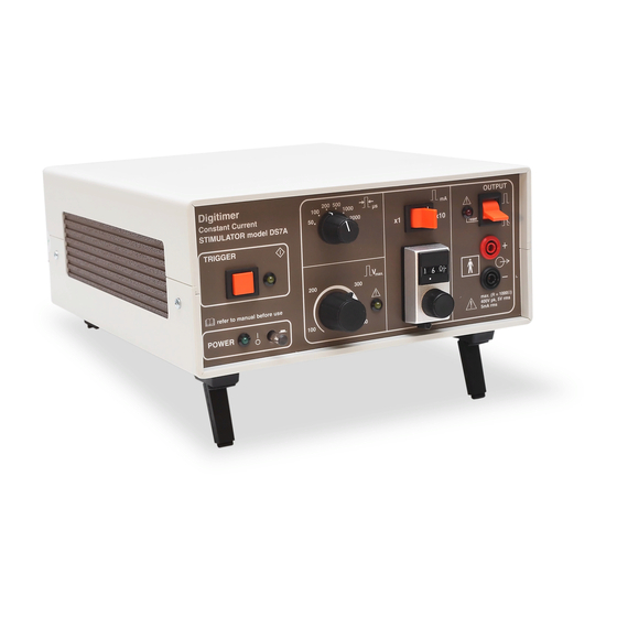
Digitimer
Constant Current Stimulator
DS7A (including DS7AH)
OPERATOR'S MANUAL
0120
The DS7A/DS7AH has been Listed for human use
in Europe, USA, Canada and other Countries.
Caution: Federal law restricts this device to sale by or on the order of a physician.
'Digitimer' is a registered Trade Mark of Digitimer Limited
Advertisement
Table of Contents

Related Manuals for Digitimer DS7A

Summary of Contents for Digitimer DS7A
- Page 1 DS7A (including DS7AH) OPERATOR’S MANUAL 0120 The DS7A/DS7AH has been Listed for human use in Europe, USA, Canada and other Countries. Caution: Federal law restricts this device to sale by or on the order of a physician. ‘Digitimer’ is a registered Trade Mark of Digitimer Limited...
- Page 2 Operator's Manual DS7A - Constant Current Stimulator Product Registration Please take time out to register your new product. Details are included in the General Information Chapter You can even do it online at:- www.digitimer.com/register Digitimer Ltd. 2 of 58 Copyright © 2014 File Ref: N:\Docs\Company\Manuals\DS7A\Issue-14\DS7A-iss14.odt...
- Page 3 Operator's Manual DS7A - Constant Current Stimulator The Digitimer DS7A & DS7AH Constant Current Stimulator NOTE: Where “DS7A” is written is this manual, details apply to the DS7A and DS7AH unless noted otherwise. Digitimer Ltd. 3 of 58 Copyright © 2014 File Ref: N:\Docs\Company\Manuals\DS7A\Issue-14\DS7A-iss14.odt...
- Page 4 Operator's Manual DS7A - Constant Current Stimulator This page is left intentionally blank to provide an insertion place of any changes subsequent to the printing of this document. Digitimer Ltd. 4 of 58 Copyright © 2014 File Ref: N:\Docs\Company\Manuals\DS7A\Issue-14\DS7A-iss14.odt Last Revised: February 1, 2017...
-
Page 5: Warning & Caution
Operator's Manual DS7A - Constant Current Stimulator Warning & Caution WARNING For Patient and Operator safety, this manual should be fully read and understood before use of this product. CAUTION Please note that where “Percutaneous Stimulation” is referred to in this document, it means “Electrical Stimulation Through the Skin”... -
Page 6: Contact Addresses
Neuberg 1-b D-65193 Wiesbaden Tel: +49 (0)611 185 1944 Fax: +49 (0)611 185 1946 E-mail: helmutwehking@wehking-med.de Please contact Digitimer for Representatives in other countries. Digitimer Ltd. 6 of 58 Copyright © 2014 File Ref: N:\Docs\Company\Manuals\DS7A\Issue-14\DS7A-iss14.odt Last Revised: February 1, 2017... -
Page 7: Purchase Information
Operator's Manual DS7A - Constant Current Stimulator Purchase Information A record of salient information, on this page, will aid the Operator should this information become necessary in the future. Date of Purchase: ____________________________________________________________ Dealer: ____________________________________________________________ Dealers Tel. Number: ____________________________________________________________ Dealers Fax Number:... -
Page 8: Product Registration
E-mail is kept to a minimum and list membership is kept in the strictest confidence. Only Digitimer Limited can send mail to members of our e- mailing lists. -
Page 9: Table Of Contents
Unpacking your DS7A Stimulator..............15 Accessories......................15 Precautions & Warnings..................15 Product Intended Usage..................18 Indications for Use.....................18 Explanation of Symbols Used on DS7A..............19 Front Panel Controls..................21 Notes on Front Panel Controls..............22 Rear Panel Controls...................23 Insertion of DS7A Stimulus Output Connector..........24 Installation & Initial Check................25 Stimulus Control....................26... - Page 10 Input trigger...................34 Output trigger..................34 Explanation of Symbols Used on Accessories............35 D185-HB1......................36 D185-HB4......................37 D185-TCx - Trigger Cables.................38 D185-FS1......................39 Connection of DS7A to an EMG System.............40 Introduction.....................40 Modes......................40 DS7A - Trigger-Out.................40 DS7A - Trigger-In...................40 Setting up the EMG system................41 Artefact Rejection.....................41 Making Trigger Connections to the DS7A............42 Symbols used in connection with the Trigger.............42...
- Page 11 Obtaining Warranty Service..............57 Product change or discontinuation............57 Please send any comments regarding this product or manual (omissions, amendments, deletions, problems, adverse events, etc.) by fax or e-mail, to Digitimer at address in this manual. Thank you Digitimer Ltd. 11 of 58 Copyright ©...
-
Page 12: Eu Declaration Of Conformity
Operator's Manual DS7A - Constant Current Stimulator EU Declaration of Conformity Digitimer Ltd. 12 of 58 Copyright © 2014 File Ref: N:\Docs\Company\Manuals\DS7A\Issue-14\DS7A-iss14.odt Last Revised: February 1, 2017... -
Page 13: Fda - Indications For Use
Operator's Manual DS7A - Constant Current Stimulator FDA – Indications for Use Digitimer Ltd. 13 of 58 Copyright © 2014 File Ref: N:\Docs\Company\Manuals\DS7A\Issue-14\DS7A-iss14.odt Last Revised: February 1, 2017... -
Page 14: Equipment Description
Short pulse durations have been made available to minimise any discomfort to the subject. The pulse duration range can be varied from 50 microseconds to 2 milliseconds in six steps. The DS7A now incorporates a stimulus polarity control which allows the operator to select between normal, reverse and alternating polarity modes. -
Page 15: Unpacking Your Ds7A Stimulator
Unpacking your DS7A Stimulator Your DS7A Stimulator was delivered in a carton which was carefully designed to protect the DS7A case against damage in shipment. It would be advisable to keep the carton in case you need to relocate or return your DS7A some time in the future. - Page 16 DS7A - Constant Current Stimulator Continued... b) Explosion and Fire. The DS7A must not be used in an explosive atmosphere or in the presence of flammable anaesthetic gases. c) High voltages Dangerous voltages are present within this unit. Do not remove covers, and refer servicing to qualified personnel.
- Page 17 Operation of the DS7A in close proximity (e.g. 1m) to a shortwave or microwave therapy equipment may produce instability in the stimulator output. q) DS7A and MRI scanners The DS7A is not suitable for use in close proximity to extreme magnetic fields, such as those generated by MRI scanners. DS7A and Defibrillators...
-
Page 18: Product Intended Usage
Product Intended Usage The Digitimer DS7A Stimulator is intended for use as shown in the “Indications for Use” section that follows. It is intended to be used by persons trained in its use. Users are expected to be able to properly operate the DS7A Stimulator and associated instruments. -
Page 19: Explanation Of Symbols Used On Ds7A
Operator's Manual DS7A - Constant Current Stimulator Explanation of Symbols Used on DS7A The majority of these symbols comply with and are documented in ISO 15223: 2012. Front Panel Output Enabled with switch in Plus; positive connection of this position... - Page 20 Operator's Manual DS7A - Constant Current Stimulator Rear Panel Digitimer have declared that this equipment complies with the Medical Equipotentiality Connector Device Directive under the supervision 0120 of Notified Body 0120 (SGS UK Ltd.) Trigger Input - signal input connector.
-
Page 21: Front Panel Controls
7. x1 and x10 RANGE selection switch. For the DS7A this gives either an output range of 0 - 10 mA, as indicated in the window of the Current Amplitude Control or 0 - 100 mA by multiplying Current Amplitude Control display by a factor of ten. -
Page 22: Notes On Front Panel Controls
12. * A FAULT is indicated by an amber LED. When lit this indicates that the unit has detected a possible internal fault and should not be used. This LED will also illuminate if the DS7A is triggered “too fast” (i.e. <10ms repetition interval) in Alternating Polarity Mode. NB: As a test, this indicator will illuminate at power-on for a few seconds. -
Page 23: Rear Panel Controls
Operator's Manual DS7A - Constant Current Stimulator Rear Panel Controls 1. Mains inlet. Connect only to correct mains supply using supplied lead with moulded mains plug. THIS UNIT MUST BE EARTHED. The mains lead must contain the PROTECTIVE EARTH CONDUCTOR. -
Page 24: Insertion Of Ds7A Stimulus Output Connector
Please note that there are two levels of force needed to insert the Stimulus Output connector into the Stimulus Output Sockets on the DS7A. Note, the pictures show a D185 which has the same sockets. This photograph shows the correct orientation. -
Page 25: Installation & Initial Check
EMG-system acquires a sweep of data. - or - If the Triggering is set for the DS7A to be triggered by the EMG-system - check that when the EMG- System sends a trigger pulse the DS7A TRIGGER indicator flashes. -
Page 26: Stimulus Control
“Too-fast” Warning and Cut-out If the trigger signal applied to the DS7A is in excess of 100Hz (10ms repetition), the amber “Too-fast” LED will illuminate. This LED will stay on for the duration of the excessive trigger rate, and for 1 second afterwards. -
Page 27: Volts Max.' Control
Operator's Manual DS7A - Constant Current Stimulator 'Volts max.' control This control sets the maximum voltage, available from which the stimulation current is generated. The User may wish to limit the maximum voltage that could appear on the electrode terminals by setting this control less than the maximum of 400 Volts. -
Page 28: Maximum Stimulus Repetition Rates
The DS7A has internal fuses that limit the amount of power that is supplied to the patient. This results in a restriction on the stimulus Repetition Rate - vs - Pulse Duration - vs - Stimulus Intensity which is shown on the graph on the following page . - Page 29 Operator's Manual DS7A - Constant Current Stimulator GRAPHS OF MAXIMUM REPETITION RATES NOTE: Frequencies above 1000 Hz are not permitted with the DS7A. Digitimer Ltd. 29 of 58 Copyright © 2014 File Ref: N:\Docs\Company\Manuals\DS7A\Issue-14\DS7A-iss14.odt Last Revised: February 1, 2017...
-
Page 30: Specifications
Selected by 10 turn dial and x1/x10 switch Dial reading 0.00 to 9.99 – DS7A giving 0 to 10 mA (9.99 mA) for x1 setting – DS7A and 0 to 100 mA (99.9 mA) for x10 setting - DS7A Dial reading 0.00 to 99.9 – DS7AH giving 0 to 100 mA (99.9 mA) for x1 setting –... -
Page 31: External Fuses
Operator's Manual DS7A - Constant Current Stimulator FAULT LED - Amber, illuminated on (i) sensed over-current internally (ii) over- current to the patient or (iii) Trigger frequency “Too-fast” in alternating polarity mode. The unit is latched in this condition until reset by the Output On/Off switch being placed in the OFF position. -
Page 32: Stimulating Electrodes
DS7A - Constant Current Stimulator Stimulating Electrodes The choice of electrodes to use with the DS7A is dependant upon the specific application and should be determined by the clinician in charge of the procedure. A wide variety of proprietary electrodes are available... -
Page 33: Mains Connection
DS7A - Constant Current Stimulator Mains Connection The DS7A is shipped complete with a safety tested mains lead (fitted with a suitable moulded mains plug) to most countries. If the mains plug supplied is not suitable please advise Digitimer Ltd of the correct plug for your country. -
Page 34: Trigger Polarity
Instructions are available from the company to Qualified Personnel only. Input trigger The DS7A is factory set to trigger from the positive going edge of an applied external signal which should be between TTL (+5V) and +15V in amplitude and of at least 5 µs duration. -
Page 35: Explanation Of Symbols Used On Accessories
Operator's Manual DS7A - Constant Current Stimulator Explanation of Symbols Used on Accessories The majority of these symbols comply with and are documented in ISO 15223: 2012. Accessories Plus; positive connection of Minus; negative connection of connection to patient (Anode) connection to patient (Cathode) Output - signal output connector. -
Page 36: D185-Hb1
The moulded twin shrouded 4 mm connector (not shown) should be inserted into the pair of DS7A Stimulus Output sockets with a Red-to-Red and Black-to-Black mating. -
Page 37: D185-Hb4
DIN 42 802-1 style “TouchProof” sockets that are colour coded to the original sockets. The moulded twin shrouded 4 mm connector (shown above, centre) should be inserted into the pair of DS7A Stimulus Output sockets with a Red-to-Red and Black-to-Black mating. -
Page 38: D185-Tcx - Trigger Cables
A number of Trigger cables are offered. These will be increased as and when necessary. Please refer to the “Connection of the DS7A to an EMG System” section of this manual for more details of the cable required and connection details. -
Page 39: D185-Fs1
The foot switch should only be inserted into the DS7A “Foot Switch” socket (rear panel) when the DS7A Output Enable switch is in the Disabled (down) position. -
Page 40: Connection Of Ds7A To An Emg System
DS7A - Trigger-In STIMULUS DS7A EMG System Trigger NOTE - If the DS7A front panel Trigger button or foot switch is pressed, a stimulus will be presented without triggering the EP system. Digitimer Ltd. 40 of 58 Copyright © 2014 File Ref: N:\Docs\Company\Manuals\DS7A\Issue-14\DS7A-iss14.odt... -
Page 41: Setting Up The Emg System
Precise methods will vary with manufacturer and model. Depending on the particular set-up used, the DS7A can often produce large amplitude stimulus artefacts. These can produce a “reject” of the recorded sweep. If this is the case the Artefact Rejection should either be turned-off (disabled) or set to ignore the large transients (stimulus artefacts) in the first part of the sweep. -
Page 42: Making Trigger Connections To The Ds7A
Operator's Manual DS7A - Constant Current Stimulator Making Trigger Connections to the DS7A All Trigger connections to the DS7A will be made to the rear panel, shown below. Symbols used in connection with the Trigger. Output - signal output Active "high" square wave connector. -
Page 43: Electrical Characteristics Of Triggers
Operator's Manual DS7A - Constant Current Stimulator Electrical characteristics of Triggers Input options Manual front panel mounted push button. Foot switch via rear panel socket. Note that only Medical grade switches should be used, such as the D185-FS1. Logic signal (+3 to +15 V) +ve edge, TTL compatible (-ve edge by internal change). -
Page 44: Bibliography
Operator's Manual DS7A - Constant Current Stimulator Bibliography 1. Agnew WF, McCreery DB: Considerations for safety in the use of extracranial stimulation for motor evoked potentials. J. Neurosurg 20:143-147, 1987. 2. Barker AT: Basic principles of magnetic stimulation of the central and peripheral nervous system. - Page 45 Evidence favouring presynaptic inhibition of Ia fibres due to the activation of group III tendon afferents. Brain 121: 373-380. Numerous papers, abstracts and booklets are available from Digitimer - please see the website www.digitimer.com for the current list and request form. Digitimer Ltd.
-
Page 46: New Instruments
DS7A - Constant Current Stimulator Appendix 1 .. DS7A Modification Record Status The DS7A has a "MOD RECORD" label fixed to its rear panel. This indicates which modifications have been performed to that unit and all numbers may NOT be struck through. - Page 47 Operator's Manual DS7A - Constant Current Stimulator Case changed to UL94 V-0 Flame Retardant material in Ivory with Brown trim. Handle assembly is removed. (CN.1982/1992) Internal circuitry added to inhibit excessive pulses due to o.c. Pulse Duration switch (CN.2002) Changed the two internal fuse holders from “clips”, which are prone to weakening over time to a “board mounted”...
-
Page 48: Performance Differences Over Standard Ds7A
100 mA on the x1 range and 1000 mA on the x10 range compared to 10 mA and 100 mA for the standard DS7A. The current output of the DS7AH can be checked on a resistance load of maximum value 3.5k ohms for the x1 range and 350 ohms for the x10 range. - Page 49 1. With SW1 open set voltage control to 400V, pulse duration 1000 microseconds and current control to 100 mA (maximum CW, x10 range). Trigger DS7A and record stimulus output potential generated across the 100R resistor - should be 10 volts peak, 1 ms wide. Check that the amber "Trigger"...
-
Page 50: Test Procedure
The DS7A is a Class 1 device with Type BF applied parts. There is no requirement, in any of these tests, to open the case of the DS7A. All repair procedures should be referred to Digitimer or a local distributor. -
Page 51: Electrical Tests
Leakage Currents - Connect the DS7A to the test equipment according to the instructions for a Class 1 device with Type BF applied parts. The applied parts of the DS7A are the red and black output terminals on the front panel. As they are Type BF they may be tested as one part. - Page 52 Compatibility Electromagnetic Emissions (Table 1) The Digitimer DS7A is intended for use in the electromagnetic environment specified below. The customer or the user of the Digitimer DS7A should assure that it is used in such an environment. Emissions test Compliance...
- Page 53 Electromagnetic Immunity (Table 2) The Digitimer DS7A is intended for use in the electromagnetic environment specified below. The customer or the user of the Digitimer DS7A should assure that it is used in such an environment. IEC 60601 test Compliance...
- Page 54 DS7A - Constant Current Stimulator Electromagnetic Immunity (Table 4) The Digitimer DS7A is intended for use in the electromagnetic environment specified below. The customer or the user of the Digitimer DS7A should assure that it is used in such an environment. Immunity IEC 60601 Compliance Electromagnetic environment –...
- Page 55 Recommended separation distances between portable & mobile RF communications equipment & the Digitimer DS7A (Table 6) The Digitimer DS7A is intended for use in an electromagnetic environment in which radiated RF disturbances are controlled. The customer or the user of the Digitimer DS7A can help prevent...
- Page 56 4. Never use multiple socket outlets plugged into one another (a “daisy chain” or from an extension lead. Should you be in any doubt over the correct steps to take when connecting the DS7A into a system, obtain advice from your orginisations Bio-engineering / Medical Physics / E.B.M.E. department. Advice may also be obtained from Digitimer Ltd.
-
Page 57: Warranty Information
Warranty Information Limited Warranty Digitimer Limited warrants to the first purchaser, for a period of one year from the date of purchase, that this Digitimer Instrument (hereafter referred to as the “Product”) will be free from defective workmanship and materials, and agrees that it will, at its option, either repair the defect or replace the defective Product or part thereof at no charge to the purchaser for parts and labour. -
Page 58: Digitimer Ltd
Operator's Manual DS7A - Constant Current Stimulator Manufactured by: Digitimer Limited 37 Hydeway Welwyn Garden City Hertfordshire AL7 3BE Telephone:- (UK) 01707 328347 (Int.) +44 1707 328347 Fax:- (UK) 01707 373153 (Int.) +44 1707 373153 E-mail:- sales@digitimer.com or technical@digitimer.com Website:- www.digitimer.com...
Need help?
Do you have a question about the DS7A and is the answer not in the manual?
Questions and answers