
Subscribe to Our Youtube Channel
Related Manuals for TESTO 0555 6451


Summary of Contents for TESTO 0555 6451
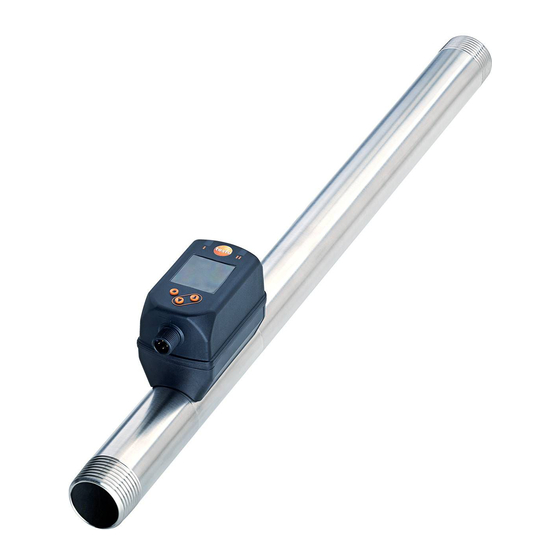
- Page 1 Operating instructions testo compressed air meter 0555 6451 0555 6452 0555 6453 0555 6454...
-
Page 2: Table Of Contents
Contents 1 Preliminary note ���������������������������������������������������������������������������������������������������5 1�1 Symbols used ������������������������������������������������������������������������������������������������5 1�2 Warnings used �����������������������������������������������������������������������������������������������5 1�3 Safety instructions �����������������������������������������������������������������������������������������5 2 Functions and features ����������������������������������������������������������������������������������������7 2�1 Pressure Equipment Directive (PED) ������������������������������������������������������������7 3 Function ���������������������������������������������������������������������������������������������������������������8 3�1 Processing of the measured signals ��������������������������������������������������������������8 3�2 Analogue output ���������������������������������������������������������������������������������������������9 3�3 Consumed quantity monitoring ��������������������������������������������������������������������... - Page 3 7�6�3 Submenu MEM �����������������������������������������������������������������������������������24 7�6�4 Submenu DIS �������������������������������������������������������������������������������������25 7�6�5 Submenu COLR ���������������������������������������������������������������������������������25 7�6�6 Submenu SIM �������������������������������������������������������������������������������������26 8 Set-up ����������������������������������������������������������������������������������������������������������������26 9 Parameter setting ����������������������������������������������������������������������������������������������27 9�1 Parameter setting in general �����������������������������������������������������������������������27 9�1�1 Select submenu ����������������������������������������������������������������������������������27 9�1�2 Change to the process value display (RUN mode) ����������������������������28 9�1�3 Lock / unlock ���������������������������������������������������������������������������������������28 9�1�4 Timeout �����������������������������������������������������������������������������������������������28 9�2 Settings for volumetric flow monitoring ��������������������������������������������������������28...
- Page 4 10 Operation ���������������������������������������������������������������������������������������������������������34 11 Error correction ������������������������������������������������������������������������������������������������34 12 Maintenance, repair and disposal ��������������������������������������������������������������������36 13 Factory setting �������������������������������������������������������������������������������������������������36...
-
Page 5: Preliminary Note
1 Preliminary note 1.1 Symbols used ► Instructions > Reaction, result […] Designation of keys, buttons or indications → Cross-reference Important note Non-compliance may result in malfunction or interference� Information Supplementary note� 1.2 Warnings used CAUTION Warning of personal injury� Slight reversible injuries may result�... - Page 6 • If the operating instructions or the technical data are not adhered to, personal injury and/or damage to property may occur� • The manufacturer assumes no liability or warranty for any consequences caused by tampering with the product or incorrect use by the operator� •...
-
Page 7: Functions And Features
2 Functions and features The unit monitors the standard volume flow of compressed air in industrial use� It detects the 5 process variables flow velocity, volumetric flow quantity, consumed quantity, medium temperature and pressure� All indications apply to standard volume flow to DIN ISO 2533, i�e� volume flow at 1013 mbar, 15 °C and 0 % relative air humidity�... -
Page 8: Function
3 Function • The volumetric flow is monitored by a calorimetric measuring system, the measured signals are evaluated by the electronics� • The unit detects the pressure and the media temperature of the volumetric flow as additional process values� • The unit displays the current process values� •... -
Page 9: 3�2 Analogue Output
3.2 Analogue output The unit provides an analogue signal that is proportional to the volumetric flow quantity, the medium temperature or the pressure� Within the measuring range the analogue signal is 4���20 mA� The measuring range is scalable: • [ASPx] determines at which measured value the output signal is 4 mA� •... - Page 10 [mA] FOU=On 21,5 20,5 FOU=OFF cr.UL UL cr.OL [% MEW] [bar] [°C] [°F] Fig� 1: Characteristics of the analogue output according to the standard IEC 60947-5-7� analogue signal measured value (volumetric flow, temperature or pressure) detection zone display range measuring range scaled measuring range flow pressure...
-
Page 11: 3�3 Consumed Quantity Monitoring
3.3 Consumed quantity monitoring The unit has an internal quantity meter (totaliser)� It continuously sums up the consumed quantity and provides this process value on the display� 3.3.1 Meter reading The current quantity meter count can be indicated (→ 7.1). In addition, the value before the last reset is saved�... -
Page 12: 3�4 Measured Value Damping
3.4 Measured value damping The damping time [dAP�F] und [dAP�P] allows to set after how many seconds the output signal has reached 63 % of the final value if the flow value / the pressure value changes suddenly� The set damping time stabilises the analogue outputs and the display�... -
Page 13: 3�7 Colour Of The Characters In The Display
3.7 Colour of the characters in the display The colour of the characters in the display can be set via the parameter [coL�x]: • Permanent definition of the display colour: - bk/wh (black/white) - yellow - green - red • Colour change from red to green or vice versa (Fig� 2): - r-cF (red display colour between the limits cFL���cFH) - G-cF (green display colour between the limits cFL���cFH) cFL = lower limit... -
Page 14: Installation
4 Installation CAUTION If the medium temperature is above 50 °C (122 °F), parts of the housing can increase in temperature to over 65 °C (149 °F)� > Risk of burns� ► Protect the housing against contact with flammable substances and unintentional contact�... -
Page 15: 4�2�2 Orientation
Interference Distance to the sensor two 90° elbows, two planes 25 x pipe diameter valve, slide 40 x pipe diameter Shut-off valves and control devices are not allowed directly in front of the unit� 4.2.2 Orientation Fig� 1: Orientation of the pipe length and the unit 1: pipe length vertical, unit any 2: pipe length horizontal, unit vertical 3: pipe length right, unit on side... -
Page 16: 4�3 Installation In Pipes
► Fit the unit in the pipe in accordance with the flow direction (arrow on the unit): ► Tighten both adapters in opposite direction by applying the defined tightening torque: Type Tightening torque 0555 6451; 0555 6452 100 Nm 0555 6453; 0555 6454 150 Nm 5 Electrical connection The device must be connected by a qualified electrician�... - Page 17 Connection 4 (OUT1) • analogue signal for volumetric flow • analogue signal for temperature • analogue signal for pressure • OFF 2 (OUT2) • analogue signal for volumetric flow • analogue signal for temperature • analogue signal for pressure • OFF...
-
Page 18: Operating And Display Elements
6 Operating and display elements ¹ ² ³ ⁵ ⁴ 1 and 2: LEDs Without function 3: TFT display • Display of the current process values (volumetric flow quantity, temperature, pressure, totaliser) • Display of the parameters and parameter values 4: [▲] and [▼] buttons •... -
Page 19: Menu
7 Menu 7.1 Process value display (RUN) It is possible to select three process value indications during operation: ► Press [▲] or [▼]. > The display changes between the standard indication and two other views� > After 30 s, the device returns to the standard display� Running... -
Page 20: 7�2 Main Menu And Extended Functions
7.2 Main menu and Extended functions (EF) Process value display (RUN) - - - - - - - - ASP1 IO-L On OFF - - - - AEP1 rES.T - - - - ASP2 2 h 3 h 4 h 5 h ... - - - - AEP2 - - - -... -
Page 21: 7�3 Submenu Out1, Out2, Cfg
7.3 Submenu OUT1, OUT2, CFG SEL1 FLOW TEMP PRES - - - - ASP1 - - - - AEP1 FOU1 OU On OFF OUT1 IO-L SEL2 FLOW TEMP PRES - - - - ASP2 Info - - - - ASP2 OUT1 OUT2 FOU2... -
Page 22: 7�4 Submenu Mem, Dis
7.4 Submenu MEM, DIS IO-L Lo.F Hi.F Lo.T Info Hi.T OUT1 Lo.P OUT2 Hi.P diS.L L2.Temp L2.Pres L2.Totl L3.TP COLR diS.U d1 d2 d3 diS.R 0 90 180 270 diS.B 25 50 75 100 OFF... -
Page 23: 7�5 Submenu Colr, Sim
7.5 Submenu COLR, SIM coL.F bk/wh red green yellow r-cF G-cF - - - cFH.F IO-L - - - cFL.F coL.T bk/wh red green yellow r-cF G-cF Info - - - cFH.T OUT1 - - - cFL.T OUT2 coL.P bk/wh red green yellow r-cF G-cF - - - cFH.P - - -... -
Page 24: 7�6 Explanation Of The Menu
7.6 Explanation of the menu 7.6.1 Submenu OUT1 and OUT2 Parameter Explanation and setting options SELx standard unit of measurement for evaluation by OUTx: FLOW (volumetric flow) or TEMP (temperature) or PRES (pressure) ASPx analogue start point for OUTx AEPx analogue end point for OUTx FOUx response of OUTx in case of an internal fault:... -
Page 25: 7�6�4 Submenu Dis
Parameter Explanation and setting options Hi�T max� value of the temperature measured in the process Lo�P min� value of the pressure measured in the process Hi�P max� value of the pressure measured in the process 7.6.4 Submenu DIS Parameter Explanation and setting options diS�L standard process value display = current process value for volumetric flow... -
Page 26: 7�6�6 Submenu Sim
Parameter Explanation and setting options coL�V colour of the characters in the display for the totaliser value bk/wh permanently black/white yellow permanently yellow green permanently green red permanently red r-cF display colour between limits cFL���cFH red, outside green� G-cF display colour between limits cFL���cFH green, outside red� 7.6.6 Submenu SIM Parameter Explanation and setting options... -
Page 27: Parameter Setting
9 Parameter setting CAUTION If the medium temperature is above 50 °C (122 °F), parts of the housing can increase in temperature to over 65 °C (149 °F)� > Risk of burns ► Do not touch the device with your hands� ►... -
Page 28: 9�1�2 Change To The Process Value Display (Run Mode)
9.1.2 Change to the process value display (RUN mode) There are 2 possibilities: 1� Wait for 30 seconds (→ 9.1.4 Timeout). 2� Press [▲] or [▼] to go to the end of the menu and change to the next higher menu�... -
Page 29: 9�3�2 Time-Controlled Counter Reset
9.3.2 Time-controlled counter reset ► Select [rTo] and set the requested value (intervals of hours, days or Menu EF: weeks)� [rTo] > The totaliser is reset automatically with the value now set� 9.3.3 Deactivation of the counter reset ► Select [rTo] and set OFF� Menu EF: >... -
Page 30: 9�6 User Settings (Optional)
9.6 User settings (optional) 9.6.1 Standard display ► Select [diS�L] and set process value display: Menu DIS: [diS�L] - L1 = current process value for volumetric flow [diS�U] - L2�Temp = current process value for flow and temperature [diS�R] - L2�Pres = current process value for volumetric flow and pressure - L2�Totl = current process value for volumetric flow and totaliser... -
Page 31: 9�6�5 Measured Value Damping
9.6.5 Measured value damping ► Select [dAP�F] for flow rate measurement or [dAP�P] for pressure Menu CFG: measurement and set damping constant in seconds (τ value 63 %). [dAP�x] 9.6.6 Low flow cut-off ► Select [LFC] and set limit, below which a current is evaluated as Menu CFG: standstill�... -
Page 32: 9�6�9 Colour Of The Characters In The Display
9.6.9 Colour of the characters in the display ► Select [coL�F] for volumetric flow or [coL�T] for temperature or [col�P] for Menu COLR: pressure and set the colour of the characters for the process value in [coL�x] the standard display: [cFH�x] [cFL�x] - bk/wh = permanently black/white... -
Page 33: 9�6�11 Restore Factory Setting
9.6.11 Restore factory setting ► Select [rES]� Menu EF: ► Briefly press [●]]� [rES] ► Keep [▲] or [▼] pressed. > [----] is displayed� ► Briefly press [●]� > The device carries out a reboot� → 13 Factory setting. We recommend taking down your own set- tings in that table before carrying out a reset�... -
Page 34: 9�7�2 Simulation
9.7.2 Simulation ► Select [S�FLW] and set the flow value to be simulated� Menu SIM: ► Select [S�TMP] and set the temperature value to be simulated� [S�FLW] ► Select [S�PRS] and set the pressure value to be simulated� [S�TMP] ► Select [S�Tim] and set the time of the simulation in minutes� [S�PRS] ►... - Page 35 ERROR ERROR Unit faulty / malfunction FOU Replace device� Supply voltage too low Check the supply voltage� Change [diS.B] setting (→ 9�6�1)� PArA Parame- Parameter setting outside FOU Repeat parameter setting� ter Error the valid range ERROR Pressure Error in pressure meas- FOU Check pressure measure- Error urement...
- Page 36 12 Maintenance, repair and disposal As a rule, no measures for maintenance are necessary� ► Define regular calibration intervals according to the process requirements� Recommendation: every 12 months� Only the manufacturer is allowed to repair the unit� ► After use dispose of the unit in an environmentally friendly way in accordance with the applicable national regulations�...
- Page 37 Menu Parameter Factory setting User setting uni.F uni.T °C uni.P dAP.F 0,6 s dAP.P 0,06 s 0555 6451 0,1 m³/h 0555 6452 0,3 m³/h 0555 6453 0,5 m³/h 0555 6454 2,0 m³/h rEF.P 1013 mbar rEF.T 15 °C diS.L L3�TP diS.U...
Need help?
Do you have a question about the 0555 6451 and is the answer not in the manual?
Questions and answers