Table of Contents
Advertisement
Quick Links
Advertisement
Table of Contents

Subscribe to Our Youtube Channel
Related Manuals for ABB C320


Summary of Contents for ABB C320
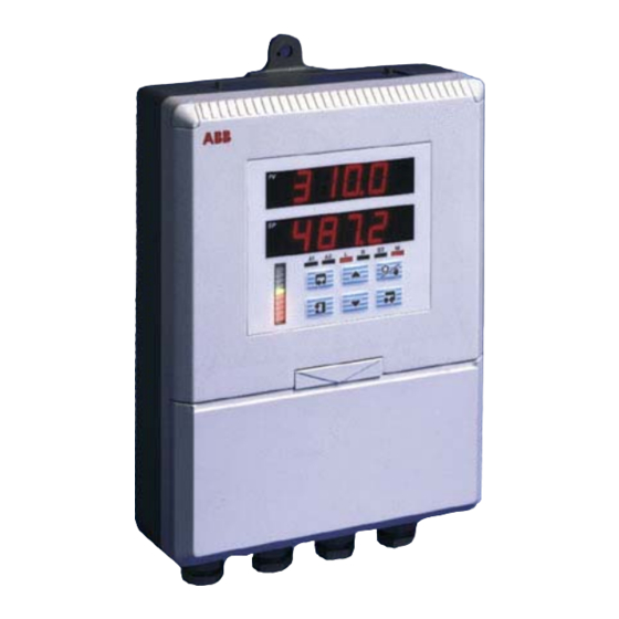
- Page 1 User Guide Booster Pump Controller IM/C320_6 C320...
- Page 2 Cert. No. Q5907 As a part of ABB, a world leader in process automation technology, we offer customers application expertise, service and support worldwide. We are committed to teamwork, high quality manufacturing, advanced EN 29001 (ISO 9001) technology and unrivalled service and support.
- Page 3 GETTING STARTED The COMMANDER 320 Booster Pump Controller acts as a differential pressure switch for use in the regeneration section of a pasteurizer. If the difference between pasteurized milk pressure and raw milk pressure falls below a preset level, the controller shuts down the raw milk booster pump or alternatively, channels the pasteurized milk into the divert flow.
-
Page 4: Table Of Contents
CONTENTS Section Page 1 DISPLAYS AND CONTROLS ................3 1.1 Introduction ......................... 3 1.2 Use of Controls ......................3 1.3 Displays and LED Indicators ..................4 1.3.1 LED Indications, Relay and Alarm States ............4 1.3.2 Deviation Bargraph ..................5 1.4 Instrument Power-up .................... -
Page 5: Displays And Controls
1 DISPLAYS AND CONTROLS 1.1 Introduction – Fig. 1.1 The Commander 320 front panel display, function keys and LED indicators are shown in Fig. 1.1 'Enter' Switch LED Displays A1 A2 Controls – Refer to Figs. 1.2 to 1.6 LED Indicators 'Data Entry' Switch (use to enter settings Deviation Bar... -
Page 6: Displays And Led Indicators
…1 DISPLAYS AND CONTROLS 1.3 Displays and LED Indicators The displays, LED indicators and operation/programming controls are located on the faceplate on the front of the instrument. The displays comprise 2 rows of 6 characters. C or c N or n O or o H or h Table 1.1 Character Set... -
Page 7: Deviation Bargraph
Switch on the supply to the instrument, any power-operated control circuits and the input signals. c) The start-up sequence shown in Fig. 1.8 is displayed when the supply is first switched on. C320 tESt Instrument Test identifies the instrument type, C320 – see Table 4.1 100. 3 CONFIG Flashing CHECK 200. -
Page 8: Operating Level
2 OPERATING LEVEL 2.1 Operating Page Information. The instrument has a dedicated Operating page. This page is used for general monitoring of the process measurements and is not affected by the security system which inhibits access to the alarm set up and programming pages – see section 3 Operating Page Pressure of raw product. -
Page 9: Security Access
2 OPERATING LEVEL… 2.4 Security Access – Figs 2.1 and 2.2 A security system is used to prevent tampering with the program parameters by utilizing a security input together with an Alarm password and a Configuration password – see Figs. 2.1 and 2.2. -
Page 10: Security Code Page
…2 OPERATING LEVEL 2.4.1 Security Code Page Page Header – Security Code Page SECOdE Set the correct Alarm or Configuration password using the switches and press the switch to enter the code. The passwords are programmed in the – see Access Page Section 3.7. -
Page 11: Configuration Level
3 CONFIGURATION LEVEL 3.1 Preparation for Changes to the Parameters Ensure that the external alarm/control circuits are isolated if inadvertent operation during programming is undesirable. Any change to the operating parameters are implemented using the switches – see Section 2. Note. -
Page 12: Set Up Alarms Page
…3 CONFIGURATION LEVEL 3.2 Set Up Alarms Page Information. • Two alarms – identified A1 and A2 . • Adjustable hysteresis value to prevent oscillation of alarm state. Pasteurized pressure input Divert Hysteresis Raw pressure Divert trip Value input level Alarm On Alarm Off Fig. - Page 13 3 CONFIGURATION LEVEL… …3.2 Set Up Alarms Page SEtUP Page Header – Set Up Alarms. ALArMS dVtrIP Divert Trip Level –––– Set the trip level for alarm A1 in engineering units. Note. When alarm A1 is active, relays 1 and 2 are de-energised. Alarm A1 can be acknowledged by the operator.
-
Page 14: Set Up Inputs
…3 CONFIGURATION LEVEL 3.3 Set Up Inputs – Fig. 3.4 Information. • All changes made apply to both the raw and pasteurized pressure inputs. • Both inputs are fixed, 4 to 20mA • Programmable fault levels and actions. • Digital filter reduces the effect of noise on inputs. Example –... - Page 15 3 CONFIGURATION LEVEL… …3.3 Set Up Input Page SEtUP Page Header – Set Up Process Variable Input. INPUt bSPd Broken Sensor Protection Drive NONE In the event of a fault being detected on the input, the displayed value is driven in the direction of the mode selected.
-
Page 16: Set Up Display Page
…3 CONFIGURATION LEVEL 3.4 Set Up Display Page Information. • Set up engineering ranges and units. • Programmable increments on deviation bargraph. • Adjust display brightness. dISPLY Page header – Display Page. PAGE dIS–HI Display Full Scale 1000 Set the display value which represents the maximum pressure input signal, between –9999 and +9999. -
Page 17: Retransmission Output Page
3 CONFIGURATION LEVEL… 3.5 Retransmission Output Page Information. • Retransmission types – allows retransmission of any two signals, i.e. raw product pressure, pasteurised product pressure, pressure difference. • Adjustable pressure difference output range. • 4 to 20mA outputs. rEtrAN Page header – Retransmission Output Page. OUtPUt tYPE Retransmission Types... -
Page 18: Scale Adjustment Page
…3 CONFIGURATION LEVEL 3.6 Scale Adjustment Page Information. • Scale Adjustment Reset – removes any previously programmed offset or scale adjustment settings. • System offset errors – can be removed using Offset Adjustment. • System scale errors – can be removed using Span Adjustment. •... - Page 19 3 CONFIGURATION LEVEL… …3.6 Scale Adjustment Page from previous page P–rSt Pasteurized Input Scale Adjustment Reset Select YES and press to reset the process variable offset and span values to their nominal values. dONE is displayed to indicate that these parameters have been reset.
-
Page 20: Access Page
…3 CONFIGURATION LEVEL 3.7 Access Page Information. • – protects the alarm settings. Alarm Password • – protects the controller configuration setup. Configuration Password ACCESS Page Header – Access Page. PAGE C–PASS Configuration Password The configuration password enables access to all programming pages (Security Level 2). -
Page 21: Commissioning
3 CONFIGURATION LEVEL 3.8 Commissioning CO __ I- Page header – Commissioning SSION ISO _ rt Isolated Retransmission Output Allows the isolated and non-isolated retransmission outputs to be inter-changed. – Outputs not interchanged (see table on page 15). – Outputs interchanged (see table on page 15 –... -
Page 22: Installation
4 INSTALLATION 4.1 Checking the Code Number – Fig. 4.1 C320/0 X X X X X X X Code Number Label – see Table 4.1 Fig. 4.1 Location of Code Number Label COMMANDER 320 Booster Pump Controller C320/ XXXX Option... -
Page 23: Siting
4 INSTALLATION… EC Directive 89/336/EEC In order to meet the requirements of the EC Directive 89/336/EEC for EMC 55°C Max. regulations, this product must not be used in a non-industrial environment. 0°C Min. 4.2 Siting – Figs. 4.2 and 4.3 A –... -
Page 24: Mounting
…4 INSTALLATION 4.3 Mounting – Figs. 4.4 and 4.5 The instrument is designed for wall-/pipe-mounting – see Fig. 4.5. Overall dimensions are shown in Fig. 4.4. 1.65 2.68 (68) (42) 6.3 (160) 8.43 9.84 9.13 (214) (250) (232) Allowance for 2.72 (69) 7.9 (200) Cable Bends... -
Page 25: Access To Terminals
4 INSTALLATION… Warning. Before making any connections, ensure that the power supply, any high voltage- operated control circuits and high common mode voltages are switched off. Note. • Always route signal leads and power cables separately, preferably in earthed metal conduit. -
Page 26: Setting The Input Selector Links
…4 INSTALLATION… 4.5 Setting the Input Selector Links – Fig. 4.7 Remove the instrument front panel – see Fig. 4.6, steps 1 to 6. The positions of the input links is shown in Fig. 4.7 detail A. 4.6 Setting the Isolated Output Link – Fig. 4.7 The positions of the isolated output links is shown in Fig. -
Page 27: Cable Glands And Conduit Fixings
4 INSTALLATION… 4.7 Cable Glands Conduit 4.7.2 Conduit Adaptors Fixings American – 0.5in) – Fig. 4.9 4.7.1 Cable Glands (IEC – 20mm) – Warning. Fig. 4.8 • Rigid conduit must NOT be fitted to the controller. • Controller adaptors must incorporate a face seal. -
Page 28: Cable Glands (N. American - 0.5In)
…4 INSTALLATION 4.7.3 Cable Glands (N. American – 0.5in) – Fig. 4.10 Warning. • Controller glands must be fitted with a face seal. • Torque settings (hubs only) – 20ft. lbs minimum, 25ft. lbs. maximum. • Outer nuts – hand tight plus a half turn only. -
Page 29: Connections Summary
4 INSTALLATION… 4.8 Connections Summary – Fig. 4.11 Information. Input impedance: Current 10Ω. Raw Pressure Input Relay 1 Relay 3 Relay 2 Pasteurized Pressure Input Power Supply 3 4 5 6 7 8 9 10 11 12 13 14 15 16 17 18 19 20 21 22 23 24 25 26 27 28 29 30 31 32... - Page 30 …4 INSTALLATION… Terminal Number AC Supply 24V, 115V or 230V a.c. – see Fig. 4.17 Relay 1 Output Booster pump or divert valve – see Fig. 4.14 Relay 2 Output Booster pump or divert valve – see Fig. 4.14 Relay 3 Output Alarm Annunciator –...
-
Page 31: Input Connections
4 INSTALLATION… 4.9 Input Connections 4.11 Logic Input Connection – Fig. 4.9.1 Current Input – Fig. 4.12 4.15 & Pasteurized pressure input Normal Raw pressure input £ Logic switching Manual override Sleeved Link – Fig. 4.12 Current Input Connections Normal Manual Override 4.9.2 2-wire Transmitter –... -
Page 32: Relay Connections
…4 INSTALLATION… 4.12 Relay Connections – Fig. 4.16 See Table 4.3 for relay and alarm states. Relay 3 Relay 2 Relay 1 Normally Open Common Normally Closed Fig. 4.16 Relay Connections Deviation Start-up Logic Relay Alarm (A1) Alarm (A2) Input 1 state Relay 1 Active... -
Page 33: Power Supply Selection And Ac Connections
4 INSTALLATION 4.13 Power Supply Selection and AC Connections – Fig. 4.17 115V Digit 7 Code Label C32 x x x x x x x x x Selector not fitted (24V AC) 230V A – Selecting the Supply Voltage Information. Fuse Rating –... -
Page 34: Specification
SPECIFICATION Outputs/Inputs Summary Relay outputs C320 Booster Pump Controller Three relays – SPDT 5A 120/240V AC normally open or normally closed: Two analog inputs Relay 1 – for booster pump or bypass valve control Three relays Relay 2 – for booster pump or bypass valve control Two analog outputs Relay 3 –... - Page 35 – Manufacturing – Metals and Minerals United Kingdom – Oil, Gas & Petrochemical ABB Limited – Pulp and Paper Tel: +44 (0)1480 475321 Fax: +44 (0)1480 217948 Drives and Motors • AC and DC Drives, AC and DC Machines, AC...
- Page 36 ABB has Sales & Customer Support expertise The Company’s policy is one of continuous product in over 100 countries worldwide improvement and the right is reserved to modify the information contained herein without notice. www.abb.com Printed in UK (08.05) © ABB 2005 ABB Limited ABB Inc.
Need help?
Do you have a question about the C320 and is the answer not in the manual?
Questions and answers