Table of Contents
Advertisement
Quick Links
Advertisement
Table of Contents

Related Manuals for Dynacord PMX-CSK


Summary of Contents for Dynacord PMX-CSK
- Page 1 PMX-CSK PROMATRIX 8000 CALL STATION KIT Owner‘s Manual...
- Page 2 Selection tables Default functions & indications Factory presets Block diagram Connections OPERATION LC-display Operation mode Call station kit mode configuration User menu Setup menu APPENDIX CAN Bus principles PMX-CSK interfaces DPC 8120 CALL STATION EXTENSION Technical data Main data Accessories Standards...
-
Page 3: Important Safety Instructions
IMPORTANT SAFETY INSTRUCTIONS The lightning flash with arrowhead symbol, within an equilateral triangle is intended to alert the user to the presence of uninsulated „dangerous voltage“ within product’s enclosure that may be of sufficient magnitude to constitute a risk of electric shock to persons. The exclamation point within an equilateral triangle is intended to alert the user to the presence of important operating and maintenance... - Page 4 We are committed to facilitate our own electronic-waste- management-system, for the free of charge return of all EVI Audio GmbH products: Telex, DYNACORD, Electro-Voice and RTS. Arrangements are made with the dealer where you purchased the equipment from, for the...
-
Page 5: System Overview
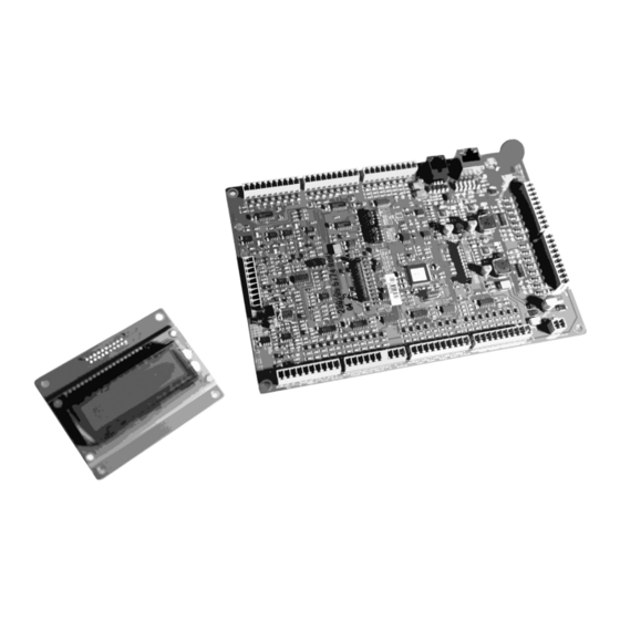
1. Introduction 1.1 System overview The PMX-CSK Call Station Kit contains a printed circuit board (PCB) that can be used to make custom-made call stations (e.g. a fireman’s panel) and belongs to the PROMATRIX 8000 product family. PMX-CSK is the kit version of the DPC 8015 with some small kit spec differentiations. -
Page 6: Scope Of Delivery And Warranty
1.2 Scope of Delivery and Warranty PMX-CSK 1 PMX-CSK CALL STATION KIT main board 1 PMX-CSK CALL STATION KIT display 1 Display connection cable (50 c m ) 1 Owner‘s manual (this document) 10 Connector 10 pole 1 Connector 2 pole, additional +24V power input 1 Safety Instructions www.dyncord.com... - Page 7 23 buttons share 6 common VCCs (3V3 - DC) Each button has short circuit protection LEDs connected to Buttons PMX-CSK support open drain outputs with max. 5mA per (Through Screw-terminal output. Using the internal supply max 100mA can be Connectors) sourced for all outputs.
-
Page 8: Top View
Top view CN5 – LED’s switch 13-15 CN4 – LED’s switch 9-12 CN13 – Additional power CN103 – Display CN1 – CN11 – connection PCA bus LED’s switch 5-8 CN200 – EXT interface CN10 – LED’s CN17 – switch 1-4 Menu keys Alarm keys S22 –... - Page 9 Connection table Number Element Description (default configuration) CN 1 PCA BUS port PCA connection for PROMATRIX 8000 CONTROLLER CN 200 EXT interface Interface for DPC 8120 CALL STATION EXTENSION Audio line input Call station Kit Mic/line connection Press to Talk connection (PTT) PTT activation (LED connection) Microphone connection LED’s switch 9-12...
- Page 10 Selection tables 2.4.1. Address setting The address of the PMX-CSK should be set by DIP switch S22. Set the address conform table 1.1. “0” = off “1” = on DIP Switch Address Table 1.2...
- Page 11 2.4.2. Baud rate setting The baud rate of the PMX-CSK should be set by DIP switch S21 and can be set to 10, 20 and/or 62,5 kbps. The baud rate setting can be found in the table 1.3: “0” = off “1”...
- Page 12 Default functions & Indications Functions and indictors for the PMX-CSK are inherited from the Promatrix DPC 8015 CALL STATION. Table 1.5. gives an overview of the default functions and indications assigned to switches and LED’s on the DPC 8016. Element...
-
Page 13: Led Indications
LED indications 2.5.1. Table 1 . 6 provides an overview of L E D s t a t e s a s s i g n e d t o t h e L E D ’ s o n t h e D P C 8 0 1 5 . T h e L E D f u n c t i o n s f o r t h e P M X - C S K a r e i n h e r i t e d f r o m t h e D P C 8 0 1 5 . -
Page 14: Factory Presets
The CALL STATION KIT provides the f o l l o w i n g characteristics: Parameter Setting / Description CAN address 0 (disconnected) Priority 5 (priority for messages) Name PMX-CSK Password Setup menu password protected, Default password: 2222 Pre-gong signal Buzzer On (acoustic alert signal) - Page 15 Bock Diagram...
- Page 16 Connections This chapter provides the way of wiring the contacts and LED’s The CALL STATION KIT inputs and outputs provide default functions as shown in table 1.7. 2.8.1. LED connection The CALL STATION KIT provides LED connections without any additional resistors etc.
- Page 17 2.8.2. Connecting a switch The CALL STATION KIT provides Switch connections without any additional resistors etc. LED’s should be connected as shown in picture 1.2 The +3V3_K connections on both ends are similar. Both can be used to drive the Switches. The additional +3V3_K is provided to enable multiple wire connections.
-
Page 18: Operation
3. Operation LC-display Depending on the actual operational status of the PROMATRIX 8000 system, the LC-display shows information on time, operation mode, user notes, set- ting up, fault messages including precise device / module specification, etc. TATUS MESSAGES During error free operation of the PROMATRIX 8000 system the LC- display shows the name / description of the call station kit in line 1 and the current date and time in line 2. -
Page 19: Operation Mode
Operation mode After power on the call station kit is in operation mode. For configuring the call station kit the setup mode is used. Several key functions differ between setup mode and operation mode, see following table. Operation mode (default configuration) Setup mode The U P input turns the system‘s power on or off. -
Page 20: Selective C All
Operation mode (default configuration) Setup mode Sx_K The 15 switch inputs with corresponding (green / Enter the corresponding yellow) LED outputs are used to pre-select areas or number of the input. Selection inputs groups for the reproduction of messages, chime or alarm signals, vocal messages, or to assign programs (close this input once = on, subsequently closing again = off). -
Page 21: General Alarm
GENERAL ALARM CAUTION: The launch of an alarm does not depend on a call station (kit) priority setting it had been activated from. Launching an alarm is possible from any microphone terminal at any time, even when the system is in stand-by mode. A running alarm is optically and occasionally also acoustically indicated at every call station (kit) A general alarm signal is always transmitted to all lines of the entire... -
Page 22: Special Functions
To switch the system off, you have to a c t i v a t e t h e d o w n _ k for approximately 3 second. This is to prevent inadvertently turning off the system. Activating an ALARM input or igniting an alarm sequence at external terminals automatically switches the PROMATRIX 8000 system’s power on and boots the system. - Page 23 ENU STRUCTURE Operation mode PROGRAM PROGRAM 1 - 4 PROGRAM + ON Program 1 Volume 1 Program assignment Program 4 Pre-Gong Volume 4 Buzzer SETUP Date / Time CAN address LCD contrast CAN baudrate CAN termination LCD brightness Firmware version LED test Password Setup Menu...
- Page 24 User menu B U S IN E S S M U S I C A SS IG N M E N T This menu item allows the assignment of business music to individual areas and groups of the entire installation. Business music transmission has always the lowest priority.
-
Page 25: Lcd Contrast
PRE-GONG It is possible to program a pre-chime signal that is heard before an announcement. The pre-chime signal is transmitted into the selected areas when activating the r e t u r n _ k i n p u t . You can begin with your announcement during the transmission of the pre-chime signal;... -
Page 26: Setup Menu
LED TEST This menu item allows a test of all call k i t station LED output contacts including call station extension if connected to the call station kit. Activate the return_k button for activating the LED test, all LEDs output contact are toggling on and off. Activating the r e t u r n _ k i n p u t again deactivates the LED output contact test and returns to the user menu. -
Page 27: Can Bus Principles
APPENDIX 4.1 CAN Bus principles The communication with the Call station Kits is done by a CAN bus protocol. The network topology used by the CAN bus is based on the so-called “bus or line topology”, i.e. all participants are connected via a single two-wire cable (Twisted-Pair cable, shielded or unshielded) with the cabling running from one participant on the bus to the next, allowing unlimited communication among all devices. -
Page 28: Pca Bus Interface
4.2 PMX-CSK interfaces PCA BUS INTERFACE The PROMATRIX CAN Audio (PCA) BUS interface is used for connecting the DPC 8015 CALL STATION or PMX-CSK CALL STATION KIT to the PROMATRIX 8000 system. The 8-pole RJ-45 connector provides power supply, control interface (CAN bus), and audio connections. - Page 29 Illustration 4-4: Assignment of PCA bus jack...
-
Page 30: Line Interface
Ensure that the correct jumper settings are assigned for the type of microphone used. The following figure shows the correct assignment of a DBB 9081/00 for using the PTT input Illustration 4-6: Assignment of PTT contact input PMX-CSK 5 - Blue PTT_PWR (VCC 3,3V) -
Page 31: Installation
4.3 DPC 8120 CALL STATION EXTENSION Up to five DPC 8120 CALL STATION EXTENSIONS can be connected to a PMX-CSK CALL STATION KIT. The call station extension provides 20 freely programmable function or zone keys having a green and yellow LED each. -
Page 32: Technical Data
Technical data Overview Main Section* CAN Interface 10, 20 and 62.5 Kbps -21dBu Maximum MIC Input Level Maximum LINE Input Level +4dBu Maximum NF Output Level +12dBu Frequency Response 200 Hz ~ 16KHz, +0 / -3 dB Nominal NF Output Level +6dBu, balanced Nominal Voltage of Main Power 24 VDC (-10% / +30%) - Page 33 CALL STATION KIT limits Main Power Supply Voltage 15 to 58 VDC Maximum Supply Current < 80mA / 24 V (External Power Supply for Lighting; Without Extensions) < 110mA / 18 V Maximum Supply Current < 150mA / 24 V (Internal Power Supply for Lighting;...
- Page 34 Bosch Security Systems BV, Torenallee 49, 5617 BA EINDHOVEN, The Netherlands www.dynacord.com Europe, Africa, and Middle East only. For customer orders, contact Customer Service at: +49 9421-706 0 Fax: +49 9421-706 265 Asia & Pacific only. For customer orders, contact Customer Service at:...
Need help?
Do you have a question about the PMX-CSK and is the answer not in the manual?
Questions and answers