Table of Contents
Advertisement
Quick Links
Document Copyrights
Copyright 2006 by Kenwood Corporation. All rights reserved.
No part of this manual may be reproduced, translated, distributed, or transmitted in any
form or by any means, electronic, mechanical, photocopying, recording, or otherwise, for
any purpose without the prior written permission of Kenwood.
Disclaimer
While every precaution has been taken in the preparation of this manual, Kenwood
assumes no responsibility for errors or omissions. Neither is any liability assumed for
damages resulting from the use of the information contained herein. Kenwood reserves
the right to make changes to any products herein at any time for improvement purposes.
文档版权信息
Kenwood Corporation 拥有版权 2006 。保留所有权利。
未经 Kenwood 公司预先书面同意,无论出于何种目的,均不得以任何形式或任何方式包
括电子、机械、影印、录音或其他方式复制、翻译、分发或传播本手册的任何部分。
免责声明
Kenwood 公司在准备本文档时已采取所有必要的预防措施,恕不对错误或疏漏承担任何
责任,也不对因使用本文中所含的信息而导致的损害负责。 Kenwood 公司保留出于改进
的需要而随时对文中的产品信息做出更改的权利。
Advertisement
Table of Contents

Related Manuals for Kenwood TK-885


Summary of Contents for Kenwood TK-885
- Page 1 Kenwood. Disclaimer While every precaution has been taken in the preparation of this manual, Kenwood assumes no responsibility for errors or omissions. Neither is any liability assumed for damages resulting from the use of the information contained herein. Kenwood reserves the right to make changes to any products herein at any time for improvement purposes.
-
Page 2: Table Of Contents
UHF FM TRANSCEIVER / UHF TK-885 SERVICE MANUAL / © 2000-10 B51-8549-00 ( N ) 607 Panel assy Cabinet (Upper) Key top (A62-0642-03) (A01-2165-13) (K29-5422-02) Cabinet (Lower) Modular jack (A01-2166-13) (E08-0877-05) CONTENTS GENERAL ..............2 OPERATING FEATURES ......... 5 REALIGNMENT ............7 INSTALLATION ............ -
Page 3: General
TK-885 GENERAL / INTRODUCTION SCOPE OF THIS MANUAL This manual is intended for use by experienced techni- cians familiar with similar types of commercial grade com- munications equipment. It contains all required service infor- mation for the equipment and is current as of the publication date. - Page 4 4-1. Antenna system Control station. The antenna system selection depends on many factors and is beyond the scope of this manual. Your KENWOOD dealer can help you select an antenna sys- tem that will best serve your particular needs. 4-2. Radio location Select a convenient location for your control station radio which is as close as practical to the antenna cable entry point.
- Page 5 TK-885 GENERAL / SERVICE This radio is designed for easy servicing. Refer to the schematic diagrams, printed circuit board views, and align- ment procedures contained in this manual. Note When you modify your radio as described in system set- up, take the following precaution.
-
Page 6: Operating Features
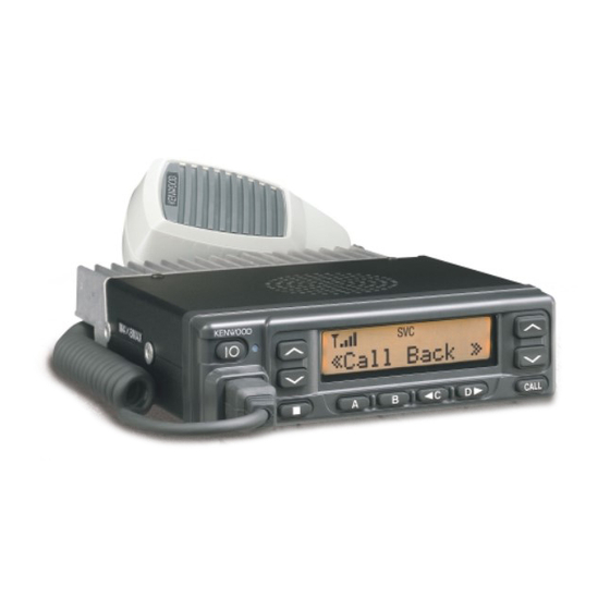
TK-885 OPERATING FEATURES / " &... - Page 7 TK-885 OPERATING FEATURES /...
-
Page 8: Realignment
TK-885 REALIGNMENT / 1. Modes User mode Panel test mode Panel tuning mode PC mode Data program- ming mode Firmware program- PC test mode PC tuning mode ming mode Mode Function User mode For normal use. Panel test mode Used by the dealer to check the funda- ment characteristics. - Page 9 5-3. KPG-46 Description (PC programming interface cable : Option) The KPG-46 is required to interface the TK-885 to the com- puter. It has a circuit in its D-subconnector (25-pin) case that converts the RS-232C logic level to the TTL level.
- Page 10 3. Set the firmware to be updated by File name item. 4. Turn the TK-885 Power ON with the [A] switch held down. Hold the switch down until the display changes to “PROG 57600”. When “PROG 57600” appears, release your fin- ger from the switch.
-
Page 11: Installation
TK-885 INSTALLATION / 1. Accessory Connection Cable (KCT-19 : Option) The KCT-19 is an accessory connection cable for connect- ing external equipment. The connector has 15 pins and the necessary signal lines are selected for use. 1-1. Installing the KCT-19 in the transceiver 1. - Page 12 TK-885 INSTALLATION / 1-2. KCT-19 Accessory Port Function No. (A) No. (B,C,D,E) Name Function Note Serial control data input (RXD2). Microphone ground. Speaker audio mute input. Ignition sense input. Receiver detector output. External microphone input. Transmitter sense output. Ground. Switched B+, DC 13.6V output.
- Page 13 TK-885 INSTALLATION / 1-3. Data Equipment Connection The jumpers must be set to either one for each function. Otherwise, the radio will not work properly. ME/AM R12 (0Ω) R167 (0Ω) Function / Default Default MI/TXS R94 (0Ω) R24 (0Ω) Function / Default...
- Page 14 TK-885 INSTALLATION / 2. Accessory Terminal (TX-RX Unit) 2-1. External Connector Accessory Terminal Method Connector Pin Function name Detect signal output. Level : 250mVrms (standard modulation) Serial data input 2 (RXD2). Ignition sense input. External modulation signal input. External microphone ground.
- Page 15 TK-885 INSTALLATION / 3. Optional Board Terminal Terminal is for mounting the option board are provided at the control and TX-RX unit. The table below shows the corre- spondence between the board and terminals. Disconnect R529 and R571 in control unit when the scrambler board is attached.
- Page 16 TK-885 INSTALLATION / 4-2. Modifying the Transceiver 4. Ignition Sense Cable (KCT-18 : Option) Modify the transceiver as follows to turn the power or the The KCT-18 is an optional cable for enabling the ignition Horn Alert or Manual Relay function on and off with the igni- function.
- Page 17 If you want to change the code, you must use the KPG-62D CPS to reconfigure the scrambler code. 5-2. Voice Scrambler Board Connection Modification 1. Remove the upper half of the case of the TK-885. 2. Remove R529 and R571 on the Control unit (X57-637 B/2). Scrambler board TK-885...
- Page 18 TK-885 INSTALLATION / 6-2. Modifying the Transceiver 6. PA/HA Unit (KAP-1 : Option) Horn alert 6-1. Installing the KAP-1 in the Transceiver The signal from pin 4 of IC7 on the TX-RX unit turns Q4 The Horn Alert (max. 2A drive) and Public Address func- and Q6 on and off and drives KAP-1 HA relay to drive the horn tions are enabled by inserting the KAP-1 W1 (3P;...
- Page 19 7. Fitting the Control Panel Upside Down The signal from pin 13 of IC7 on the TX-RX unit drives PA The TK-885 control panel can be fitted upside down, so relay (K1) in the KAP-1 and switches the audio power ampli-...
- Page 20 TK-885 INSTALLATION / 6. Rotate the control panel 180 degrees and mount it on the 8-2. KES-4 : Option transceiver. Refit the two halves of the case to complete The KES-4 is an external speaker used with the accessory installation. (Fig. 14) connection cable.
-
Page 21: Circuit Description
TK-885 CIRCUIT DESCRIPTION / Frequency Configuration Receiver System The TX-RX unit incorporates a VCO, based on a fractional Outline N type PLL synthesizer system, that allows a channel step of The incoming signal from the antenna passes through a 5, 6, and 25kHz to be selected. The incoming signal from the... - Page 22 TK-885 CIRCUIT DESCRIPTION / D211 Q201 IC200 Q203 D209,210 IC11 – MIX,IF ,DET CF1/ 1st local OSC (HT) local OSC Fig. 2 Receiver system / Wide/Narrow Changeover Circuit AF Signal System The W/N port (pin 11) of the shift register (IC7) is used to The detection signal (DEO) from the TX-RX unit goes to switch between ceramic filters.
- Page 23 VCO/PLL Circuit The TK-885 has a VCO for the transmitter and a VCO for the receiver in a sub-unit (A1). They are housed in a solid shielded case and connected to the TX-RX unit through CN101.
- Page 24 TK-885 CIRCUIT DESCRIPTION / IC711 IC504 Q103 Q106 Q202 Q204 Q205 IC400 AF AMP , RF AMP BUFFER RF AMP SUM AMP RF AMP RF AMP POWER AMP AF AMP IDC, LPF 2SK508NV 2SC4226 2SC5110 2SC4093 TA75W558FU 2SC3357 2SC2954 M68762SL...
- Page 25 TK-885 CIRCUIT DESCRIPTION / Q202,204 Q205 IC400 D209 POWER D27,30 POWER DRIVER DRIVER (TX : 8V) IC7 5pin CONTROL 25W (High power) 23pin : "H" TX : PC SW ON Fig. 8 APC circuit / Control Circuit The CPU carries out the following tasks: 1) Controls the shift register (IC7, IC8, IC508) AF MUTE, WIDE/ NARROW, T/R KEY outputs.
- Page 26 TK-885 CIRCUIT DESCRIPTION / Memory Circuit Display Circuit The transceiver has a 2M-bit (256k x 8) flash ROM (IC510) The CPU (IC511) controls the shift register (IC508) and dis- and an 16k-bit EEPROM (IC512). The flash ROM contains play LEDs. When the LG line goes high when the transceiver firmware programs, data and user data which is programmed is busy, Q508 turns on and the green LED on D511 lights.
- Page 27 Key Matrix Circuit Encode The TK-885 front panel has ten keys. Each of them is con- The QT, DQT signals are output from LSDO of the CPU nected to a cross point of a matrix of the KEY1 to KEY7 ports (IC511) and go to the D/A converter (IC5) of the TX-RX unit.
- Page 28 TK-885 CIRCUIT DESCRIPTION / Decode D/A Converter The signal (DEO) detected by the TX-RX unit passes The D/A converter (IC5) is used to adjust TONE and MO through two low-pass filters of IC501, goes to LSDI of the modulation, beep, AF volume, TV voltage, FC reference volt- CPU (IC511) to decode QT, DQT.
- Page 29 TK-885 CIRCUIT DESCRIPTION / PA Switch Power Supply Circuit If the optional KAP-1 is used, the PA (Public Address) func- When the POWER switch on the control unit is pressed, tion becomes available. In this case, the signal flow changes the PSW signal goes low.
-
Page 30: Semiconductor Data
TK-885 SEMICONDUCTOR DATA / Microprocessor : 30620M8-394GP (TX-RX Unit IC511) Terminal function Pin No. Name Function LSDOUT Low speed data output. HSDOUT High speed data output. HSDIN High speed data input. DTMSTD DTMF decode IC data detect input. SELF No function. - Page 31 TK-885 SEMICONDUCTOR DATA / Pin No. Name Function RFCLK Common clock output. (TX-RX unit) Not used. Not used. HOLD Not used. HLDA Not used. BLCK Not used. Flash memory RD bus. Not used. Flash memory WR bus. DTMCLK DTMF decode IC clock output.
- Page 32 TK-885 SEMICONDUCTOR DATA / Shift Register : BU4094BCFV Terminal function (TX-RX unit IC508) Pin No. Port Name Function Strobe Data Clock LEDR Red LED. H : ON, L : OFF LEDG Green LED. H : ON, L : OFF KEYBLT Key back light.
- Page 33 TK-885 SEMICONDUCTOR DATA / Terminal function (TX-RX unit IC8) Pin No. Port Name Function Strobe Data Clock Audio mute 1. H : Mute, L : Unmute No function VCO shift switching. H : TX, L : RX DET mute. H : RX, L : TX...
-
Page 34: Description Of Components
TK-885 DESCRIPTION OF COMPONENTS / TX-RX Unit (X57-6373-01) (A/2) Ref. No. Use / Function Operation / Condition DC amp FC, TCXO control DET amp External DEO, internal DEO Amp/Summing amp DI / DI and MO addtion Analog switch DI switch... - Page 35 TK-885 DESCRIPTION OF COMPONENTS / Ref. No. Use / Function Operation / Condition H/L switch Active while RF power is High SB SW control Active while power switch is on SB SW control Active while power supply voltage is more than 20V...
- Page 36 TK-885 DESCRIPTION OF COMPONENTS / Ref. No. Use / Function Operation / Condition IC508 Shift register LR, LG, KBLC, MM1, T/R, KEY, BSFT, PA2 output IC509 Reset Low voltage output when powering up IC510 Flash ROM IC511 IC512 EEPROM IC513...
-
Page 37: Parts List
TK-885 PARTS LIST / New Parts. indicates safety critical components. L : Scandinavia K : USA P : Canada Parts without Parts No. are not supplied. Y : PX (Far East, Hawaii) T : England E : Europe Les articles non mentionnes dans le Parts No. ne sont pas fournis. - Page 38 TK-885 PARTS LIST / TX-RX UNIT (X57-6373-01) Desti- Desti- Ref. No. Address Parts No. Description Ref. No. Address Parts No. Description parts nation parts nation CK73GB1C104K CHIP C 0.10UF C156,157 CK73GB1E103K CHIP C 0.010UF CC73GCH1H120J CHIP C 12PF C158,159 CC73GCH1H100D...
- Page 39 TK-885 PARTS LIST / TX-RX UNIT (X57-6373-01) Desti- Desti- Ref. No. Address Parts No. Description Ref. No. Address Parts No. Description parts nation parts nation C311 CC73GCH1H100D CHIP C 10PF C544 CC73GCH1H030C CHIP C 3.0PF C312 CC73GCH1H070D CHIP C 7.0PF...
- Page 40 TK-885 PARTS LIST / TX-RX UNIT (X57-6373-01) Desti- Desti- Ref. No. Address Parts No. Description Ref. No. Address Parts No. Description parts nation parts nation C710 CK73GB1C104K CHIP C 0.10UF L92-0138-05 FERRITE CHIP C711,712 CK73GB1H222K CHIP C 2200PF L40-1575-44 SMALL FIXED INDUCTOR (15.0NH)
- Page 41 TK-885 PARTS LIST / TX-RX UNIT (X57-6373-01) Desti- Desti- Ref. No. Address Parts No. Description Ref. No. Address Parts No. Description parts nation parts nation RK73GB1J224J CHIP R 220K 1/16W R114 RK73GB1J392J CHIP R 3.9K 1/16W RK73GB1J104J CHIP R 100K...
- Page 42 TK-885 PARTS LIST / TX-RX UNIT (X57-6373-01) Desti- Desti- Ref. No. Address Parts No. Description Ref. No. Address Parts No. Description parts nation parts nation R233 RK73GB1J470J CHIP R 1/16W R512 RK73GB1J681J CHIP R 1/16W R234 RK73GB1J150J CHIP R 1/16W...
- Page 43 TK-885 PARTS LIST / TX-RX UNIT (X57-6373-01) Desti- Desti- Ref. No. Address Parts No. Description Ref. No. Address Parts No. Description parts nation parts nation R588 RK73GB1J473J CHIP R 1/16W R718 RK73GB1J154J CHIP R 150K 1/16W R589 R92-1368-05 CHIP R...
- Page 44 TK-885 PARTS LIST / TX-RX UNIT (X57-6373-01) PLL/VCO (X58-4723-01) Desti- Desti- Ref. No. Address Parts No. Description Ref. No. Address Parts No. Description parts nation parts nation TA78L05F IC (VOLTAGE REGULATOR 5V) Q503 2SC4617(S) TRANSISTOR IC10 LA4422 IC (AF POWER AMP 5.8W)
- Page 45 TK-885 PARTS LIST / PLL/VCO (X58-4723-01) SUB UNIT (X58-4850-11) Desti- Desti- Ref. No. Address Parts No. Description Ref. No. Address Parts No. Description parts nation parts nation D101-104 1SV283 VARIABLE CAPACITANCE DIODE D105 1SV214 VARIABLE CAPACITANCE DIODE Q101 2SK508NV(K52) Q102...
-
Page 46: Exploded View
TK-885 EXPLODED VIEW / Parts with the exploded numbers larger than 700 are not supplied. -
Page 47: Packing
TK-885 PACKING / 38 Protection bag 39 Protection bag (H25-0103-04) (H25-0720-04) 5 Cap (B09-0235-05) 12 DC cord (E30-3339-05) 24 Fuse (F51-0016-05) 43 Bracket (J29-0627-23) 37 Inner packing case (H12-1391-03) 47 Screw set (N99-0395-05) 36 Polystyrene foamed fixture (R) (H10-6619-12) 39 Protection bag... - Page 48 TK-885 ADJUSTMENT / Test Mode Test Mode Operating Features This transceiver has a test mode. To enter test mode, press [B] key and turn power on. Hold [B] key until test channel No. and test signalling No. appears on LCD. Test mode can be inhibited by programming.
- Page 49 TK-885 ADJUSTMENT / Frequency and Signalling The set has been adjusted for the frequencies shown in the following table. When required, re-adjust them following the adjustment procedure to obtain the frequencies you want in actual operation. Frequency (MHz) Channel No.
- Page 50 TK-885 ADJUSTMENT / Press [A], now in tuning mode. Use [ C] button to write Tuning Mode Flow Chart / tuning data through tuning modes, and [System Up/Down] to adjust tuning requirements (1 to 256 appears on LCD). FREQ xxx...
-
Page 51: Adjustment
TK-885 ADJUSTMENT Test Equipment Required for Alignment Test Equipment Major Specifications 1. Standard Signal Generator Frequency Range 300 to 400MHz (SSG) Modulation Frequency modulation and external modulation Output –127dBm/0.1µV to greater than –7dBm/100mV 2. Power Meter Input Impedance 50Ω Operation Frequency... - Page 52 TK-885 & – 1 : BLC 2 : PSB 3 : E 4 : PTT 5 : ME 6 : MIC 7 : HOOK 8 ; CM...
- Page 53 Repair Jig (Chassis) The tuning data (Deviation, Squelch, etc.) for the Use jig (Part No. : A10-4010-02) for repairing the TK-885. EEPROM, is stored in memory. When parts are changed, The jig facilitates the voltage check when the voltage on the readjust the transceiver.
- Page 54 TK-885 TX/RX indicator Power Volume System switch up/down up/down TX-RX UNIT (A/2) TC106 PLL/VCO Microphone CALL jack TC109...
- Page 55 TK-885 ADJUSTMENT Receiver Section Measurement Adjustment Item Condition Specifications/Remarks Test- Unit Terminal Unit Parts Method equipment 1. Discriminator 1) Set test mode Rear TX-RX L6 AF output voltage CH : CH1 - Sig1 panel (A/2) maximum. SSG output : –53dBm AF VTVM AF : 1.4V/4Ω...
- Page 56 TK-885...
- Page 57 TK-885 ADJUSTMENT Measurement Adjustment Item Condition Specifications/Remarks Test- Unit Terminal Unit Parts Method equipment 3) “H LRSI” Rear Writing values only. SSG freq’ : 389.950MHz panel AF VTVM 4) “wL LRSI”, “wC LRSI”, Distortion (EXT.SP) “wH LRSI” meter SSG freq’ : Same as Oscilloscope narrow adjustment.
- Page 58 TK-885...
- Page 59 TK-885 ADJUSTMENT Transmitter Section Measurement Adjustment Item Condition Specifications/Remarks Test- Unit Terminal Unit Parts Method equipment 1. Frequency 1) Set test mode Power meter Rear Check 370.100MHz±100Hz Select “FREQ” in tuning mode. F. counter panel PTT : ON ± 0.5W 2.
- Page 60 TK-885...
- Page 61 TK-885 ADJUSTMENT Measurement Adjustment Item Condition Specifications/Remarks Test- Unit Terminal Unit Parts Method equipment 7. Maximum 1) Set test mode Power meter Rear 2.05kHz (Narrow) +0Hz, –50Hz deviation Connect AG to the MIC Deviation panel 4.1kHz (Wide) (Wide/Narrow) terminal. meter (According to the Select “MAX”...
- Page 62 TK-885...
- Page 63 TK-885 ADJUSTMENT Measurement Adjustment Item Condition Specifications/Remarks Test- Unit Terminal Unit Parts Method equipment ± 0.1kHz (Narrow) 11. DTMF 1) Set test mode Power meter Rear 1.5kHz (Narrow) ± 0,2kHz (Wide) deviation Select “DTMF” in tuning mode. Deviation panel 3.0kHz (Wide)
- Page 64 TK-885...
-
Page 65: Terminal Function
TK-885 TERMINAL FUNCTION CN7 (TX-RX Unit) ← → CN502 (Control Unit) CN101 (VCO) ← → TX-RX Unit Pin No. Name Function Pin No. Name Function Wide/Narrow switch. H : wide Switched transmit input. H : Transmit TX/RX switch. H : Receive RF output. - Page 66 TK-885...
-
Page 67: Pc Board Views
TK-885 PC BOARD VIEWS / PC SUB UNIT (X58-4850-11) PLL/VCO (X58-4723-01) Component side view Component side view J72-0733-02 9C IN C115 C119 CN101 L105 L109 L103 R104 C104 R119 C117 C122 L107 Q105 Q106 R109 R118 Q102 J72-0785-02 R111 R110... - Page 68 TK-885 PC BOARD VIEW / PC Ref. No. Address Ref. No. Address Ref. No. Address Ref. No. Address Ref. No. Address TX-RX UNIT (X57-6373-01) (A/2) Component side view Q403 IC10 IC11 Q203 D211 IC14 Q300 D902 Component side IC300 Q301...
- Page 69 TK-885 PC BOARD VIEW / PC Ref. No. Address Ref. No. Address Ref. No. Address Ref. No. Address Ref. No. Address Ref. No. Address Ref. No. Address TX-RX UNIT (X57-6373-01) (A/2) Foil side view IC13 IC15 Q15 12K IC200 12Q...
-
Page 70: Tx-Rx Unit (X57-6373-01) (A/2)
TK-885 PC BOARD VIEW / PC TX-RX UNIT (X57-6373-01) (A/2) Ref. No. Address Ref. No. Address Ref. No. Address Ref. No. Address Ref. No. Address Ref. No. Address Ref. No. Address Ref. No. Address IC14 Q204 D209 Component side view + Foil side... -
Page 71: Tx-Rx Unit (X57-6373-01) (B/2)
TK-885 PC BOARD VIEWS / PC TX-RX UNIT (X57-6373-01) (B/2) Component side view J72-0782-02 B/2 D512 R514 D517 R710 R517 C712 R510 C710 C527 C518 C583 R526 R713 IC710 L507 R525 R682 IC502 C524 R572 D511 C592 IC501 IC508 R531... - Page 72 TK-885 PC BOARD VIEW / PC TX-RX UNIT (X57-6373-01) (B/2) Component side view + Foil side J72-0782-02 B/2 D512 R520 R514 D517 R710 C607 R517 C712 MPTT C516 R518 R510 C515 C527 C710 C518 C583 R525 R680 R521 RXAO R526...
-
Page 73: Schematic Diagram
TK-885 SCHEMATIC DIAGRAM / Note : Components marked with a dot (·) are parts of patterun 1. - Page 74 TK-885 Note : Components marked with a dot (·) are parts of patterun 1. SCHEMATIC DIAGRAM /...
-
Page 75: Block Diagram
TK-885 TK-885 TK-885 BLOCK DIAGRAM /... -
Page 76: Level Diagram
TK-885 TK-885 LEVEL DIAGRAM / Receiver Section / W –93.5dBm W –99.5dBm N –88.0dBm N –95.0dBm CF1/ –118.0dBm –122.0dBm –116.0dBm –116.0dBm –108.0dBm –121.0dBm –109.0dBm 62mVrms 30mVrms 820mVrms 820mVrms 16mVrms 0.45Vrms BPF/ SG input level for 12dB SINAD are obtained measured by AF VTVM connecting SG to each point via a 0.01µF capacitor. -
Page 77: Specifications
TK-885 SPECIFICATIONS GENERAL Frequency Range ........ 350 to 390MHz Number of Channels ......Trunking mode : Maximum 1023 channels Conventional mode : Maximum 32 channels Channel Spacing ......... 12.5kHz/25kHz Input Voltage ........13.6V± 15% negative ground Current Drain ........0.4A on standby 1.0A on receive... - Page 78 TK-885...
- Page 79 Mechelsesteenweg 418 B-1930 Zaventem, Belgium KENWOOD ELECTRONICS FRANCE S.A. 13, Boulevard Ney, 75018 Paris, France KENWOOD ELECTRONICS U.K. LIMITED KENWOOD House, Dwight Road, Watford, Herts., WD1 8EB United Kingdom KENWOOD ELECTRONICS EUROPE B.V. Amsterdamseweg 37, 1422 AC Uithoorn, The Netherlands KENWOOD ELECTRONICS ITALIA S.p.A.
Need help?
Do you have a question about the TK-885 and is the answer not in the manual?
Questions and answers