Table of Contents
Advertisement
Quick Links
Advertisement
Table of Contents

Related Manuals for HGM COMPUSHIFT II


Summary of Contents for HGM COMPUSHIFT II
- Page 1 COMPUSHIFT II Manual COMPUSHIFT II Manual Exported on 12/08/2020...
-
Page 2: Table Of Contents
COMPUSHIFT II Manual – COMPUSHIFT II Manual Table of Contents Preparing for Your Installation .................12 Engine Preparation ........................ 12 Transmission Preparation ..................... 12 Additional Planning ....................... 12 Other Considerations......................13 Tools You Will Need........................ 13 Tools You May Need ....................... 13 Installation Notes for GM 4L80E / 4L60E Series .............. - Page 3 COMPUSHIFT II Manual – COMPUSHIFT II Manual 3.2.2.2 TOSS Locations for Different Transmissions ...................... 24 3.2.3 Connect the Lever Sensor Connector, if applicable ................... 24 3.2.4 Connect to the Reproduced TOSS Signal ......................25 3.2.5 Connect the Transfer Case Calculation Wire (4WD) ................... 25 Install the Power &...
- Page 4 COMPUSHIFT II Manual – COMPUSHIFT II Manual 3.6.1 Installing the Switch ............................39 3.6.2 Using the Switch ..............................39 3.6.2.1 SETUP Screens ..............................40 Install the Overdrive Cancel Switch (Optional) ..............40 3.7.1 Installing the Switch ............................40 3.7.2 Using the Switch ..............................41 Install the Manual TCC Switch (Optional) ................
- Page 5 COMPUSHIFT II Manual – COMPUSHIFT II Manual 4.2.9 Transfer Case Ratio .............................. 55 4.2.10 Final Drive Ratio ..............................56 4.2.11 Speedometer Calibration ............................ 56 4.2.12 Tire Diameter................................ 56 4.2.13 Vehicle Weight ..............................57 4.2.14 TCC Mode................................57 4.2.15 TCC Enable Gear..............................57 4.2.16 TCC Maximum Throttle ............................
- Page 6 COMPUSHIFT II Manual – COMPUSHIFT II Manual Using the Overdrive Cancel Switch (Optional) ..............73 Diagnostics & Troubleshooting ................74 Status LED and Display ......................74 Faults ............................74 6.2.1 Driver Fault ................................74 6.2.2 TPS Signal Low ..............................75 6.2.3 TPS Signal High ..............................
- Page 7 COMPUSHIFT II Manual – COMPUSHIFT II Manual Installing the AccuLink Refit Kit..................... 83 7.5.1 Introduction ................................. 83 7.5.2 Installation Planning............................83 7.5.3 Required Tools and Supplies..........................83 7.5.4 Removing the Old System ........................... 84 7.5.5 Removing the Sensor ............................85 7.5.6...
- Page 8 COMPUSHIFT II Manual – COMPUSHIFT II Manual 8.3.1.1 Type ..................................98 8.3.1.2 Display Characteristics ............................98 8.3.1.3 Chassis .................................. 98 8.3.1.4 Environmental Requirements ..........................99 8.3.1.5 Shock & Vibration..............................99 8.3.1.6 Electrical Specifications............................99 8.3.1.7 Display Formats ..............................99 8.3.1.8 Running Dashboard Displays ..........................99 8.3.1.9 On-the-fly adjustments............................
- Page 9 COMPUSHIFT II Manual – COMPUSHIFT II Manual 8.6.5 Pinouts for Ford 4R100 ............................121 8.6.5.1 TRANS 1 Connector ............................121 8.6.5.2 ENGINE Connector ............................. 123 8.6.5.3 OPTIONS Connector............................125 8.6.6 Pinouts for Ford AODE ............................128 8.6.6.1 TRANS 1 Connector ............................128 8.6.6.2 ENGINE Connector .............................
- Page 10 COMPUSHIFT II Manual – COMPUSHIFT II Manual HGM Automotive Electronics thanks you for buying COMPUSHIFT II. This transmission control system is a quality product that works exceptionally well. This owner's manual is organized in the sequence for a proper install. We highly recommend you review it in advance and follow it closely as you work.
- Page 11 No part of this book may be reproduced in any form or by any electronic or mechanical means without permission of HGM Automotive Electronics Corporation. All software, circuit designs, and creative content in COMPUSHIFT II are copyright © 2000 - 2017 by HGM Automotive Electronics Corporation.
-
Page 12: Preparing For Your Installation
Take the time now to plan your installation – it will save you more time down the road! 1.1 Engine Preparation When you ordered COMPUSHIFT II, you had to choose from one (1) of three (3) Throttle Position Sensor (TPS) systems: The AccuLink TPS for vehicles with Edelbrock AFB, Holley and Rochester Quadrajet carburetors;... -
Page 13: Other Considerations
(see page 56) • COMPUSHIFT II also provides a signal that duplicates the speed sensor (TOSS) in your transmission. This can be used to run an original in-dash speedometer , and eliminates the need for dual speed sensors. -
Page 14: Installation Notes For Gm 4L80E / 4L60E Series
Overdrive (4th gear) is disabled. Though the COMPUSHIFT II Kit does not provide it an Overdrive Cancel switch, one can be connected to the wire labeled "OVERDRIVE CANCEL" on the Engine & Power wiring harness. Connect this wire to a SPST/NO, MOM (single- pole, single throw normally open momentary) switch that connects to ground when turned on. - Page 15 COMPUSHIFT II Manual – COMPUSHIFT II Manual An LED lamp can be connected to the wire labeled "OVERDRIVE CANCEL INDICATOR". One side of the LED should be connected to the wire, and the other side connected to ground. You do not need to use the "OVERDRIVE CANCEL" or "OVERDRIVE CANCEL INDICATOR" wires unless you want to prohibit fourth gear.
-
Page 16: Unpacking & Inspecting Your Kit
RPM rules are programmed into the unit. It will also tell you which of the optional components and wiring harness was included. When you ordered COMPUSHIFT II, you had to choose from one (1) of three (3) Throttle Position Sensor (TPS) systems: The AccuLink TPS for vehicles with Edelbrock AFB, Holley and Rochester Quadrajet carburetors;... -
Page 17: Transmission Wiring Harness
& Tuning Your System (see section. page 44) 2.3 Transmission Wiring Harness The Transmission Wiring Harness, shown here (or one similar), connects the COMPUSHIFT II Controller to the transmission. See here for installation instructions (see page 22) Unpacking & Inspecting Your Kit – 17... -
Page 18: Power & Engine Wiring Harness
COMPUSHIFT II Manual – COMPUSHIFT II Manual 2.4 Power & Engine Wiring Harness The Power & Engine Wiring Harness, shown here (or one similar) connects the COMPUSHIFT II Controller to the vehicle's TPS, tachometer, speedometer and power. See here for installation instructions (see page 25) Each harness has a rubber grommet for the firewall. -
Page 19: Switch-Shift Harness
COMPUSHIFT II Manual – COMPUSHIFT II Manual 2.6 Switch-Shift Harness COMPUSHIFT II includes the option to connect the Switch-Shift feature, allowing you to manually upshift and downshift via pushbutton controls or paddle shifter. Switch-Shift uses an additional Switch-Shift Wiring Harness (see photo) that connects the Transmission Wiring Harness with the pushbutton controls. -
Page 20: The Tps Connector For An Electronic Fuel Injection (Optional)
COMPUSHIFT II Manual – COMPUSHIFT II Manual 2.8 The TPS Connector for an Electronic Fuel Injection (Optional) 2.8.1 For an Electronic Fuel Injection Engine with a standard GM TPS Most EFI engines have their own built-in Throttle Position Sensor (TPS), and you'll only need our provided adapter harness to tap into the signal. -
Page 21: For Other Types Of Electronic Fuel Injection Engines
(see page 36) 2.9 Cable Operated Throttle Position Sensor (Optional) If you have a mechanically-actuated throttle that cannot accommodate AccuLink TPS, HGM Automotive Electronics offers a Cable TPS and Sensor Box. The parts in the kit are shown in the photo. -
Page 22: Installation
Don't do anything like this! The COMPUSHIFT II controller is a sealed assembly. Do not open the controller case – this will void the warranty! 3.2 Install the Transmission Harness Once you have selected a place to mount the COMPUSHIFT II Controller as explained on the page, Find &... -
Page 23: Connect The Main Transmission Plug
COMPUSHIFT II Manual – COMPUSHIFT II Manual The harness has a blue connector to the Controller and four or five connections to the transmission, depending on your transmission: Main Transmission Plug (see page 23) TOSS Sensor Connector (see page 23) -
Page 24: Toss Locations For Different Transmissions
Top of extension housing 3.2.3 Connect the Lever Sensor Connector, if applicable The COMPUSHIFT II transmission harness for some transmissions have an additional connector. For a Ford 4R70W or 4R100 transmission, the Digital Range Sensor connector is separate from the main plug. -
Page 25: Connect To The Reproduced Toss Signal
COMPUSHIFT II. This signal is sent via a purple/white wire labeled "Reproduced TOSS" on the Transmission Wiring Harness. Do not attempt to connect your original TOSS wires to the TOSS wires now used by COMPUSHIFT II! If you need a TOSS signal, only use the Reproduced TOSS Signal via the purple/white wire labeled "Reproduced TOSS."... -
Page 26: Connect The Throttle Position Sensor
Do not connect the tachometer input to the coil of an electronic capacitive discharge (CD) ignition. This may damage COMPUSHIFT II and void your warranty. Installation – 26... -
Page 27: Connect The Switch-Shift Harness
3.4 Install or Connect a Throttle Position Sensor When you ordered COMPUSHIFT II, you had to choose from one (1) of three (3) Throttle Position Sensor (TPS) systems: The AccuLink TPS for vehicles with Edelbrock AFB, Holley and Rochester Quadrajet carburetors; or A wiring harness for Electronic Fuel Injection (EFI) vehicles that have their own TPS;... -
Page 28: Find The Acculink Tps Parts
COMPUSHIFT II Manual – COMPUSHIFT II Manual Sorry, the widget is not supported in this export. But you can reach it using the following URL: http://www.youtube.com/watch?v=dL7vZdjkIos 3.4.1.1 Find the AccuLink TPS Parts You should have the following parts: • Sensor bracket •... -
Page 29: Assemble And Install The Ratio Arm
COMPUSHIFT II Manual – COMPUSHIFT II Manual 3.4.1.3 Assemble and Install the Ratio Arm • Find the Ratio Arm from your COMPUSHIFT II Kit. It's the small oval piece of metal (shown here) with a protruding stud on its smaller end. •... -
Page 30: Assemble The Adjustable Arm
COMPUSHIFT II Manual – COMPUSHIFT II Manual 3.4.1.5 Assemble the Adjustable Arm The Adjustable Arm from your COMPUSHIFT II Kit contains two (4) pieces: • Fixed, threaded section • Sliding section • Two screws Find and assemble the Adjustable Arm, leaving the screws gently snug. -
Page 31: Set The Adjustable Arm Length
COMPUSHIFT II Manual – COMPUSHIFT II Manual 3.4.1.7 Set the Adjustable Arm Length • Connect the fixed, threaded section of the Adjustable Arm to the Ratio Arm.The screw heads should face outward, away from the carburetor. • Adjust the arm length so the edge of the sliding section's slot is aligned with the center of the TPS pin (as shown here) for the correct length. -
Page 32: Check The Linkage
COMPUSHIFT II Manual – COMPUSHIFT II Manual The TPS should not reach the end of its rotation or stroke in either direction, but be slightly off the stop at each end of its travel. Failure to achieve this could result in poor operation. -
Page 33: Connect The Acculink Tps To The Harness
Your system may have been shipped with an extension cable to connect the AccuLink TPS to the Controller if it's mounted far from the engine. If necessary, route the extension cable between the COMPUSHIFT II Controller and the TPS. -
Page 34: Secure The Wiring Harness To The Acculink Tps
COMPUSHIFT II Manual – COMPUSHIFT II Manual 3.4.1.12 Secure the Wiring Harness to the AccuLink TPS • From the bottom, feed the supplied cable tie and insert it through the slot in the TPS bracket. • Cinch the cable tie around the wiring harness. -
Page 35: Mount The Cable Bracket
After installing the Sensor Box, plug in the sensor connector. If you have any questions about your ability to do this part of the job, get help from a qualified mechanic. Our distributors and the HGM headquarters are also available to advise you. Installation – 35... -
Page 36: Install The Efi Tps Adapter Harness (Optional)
If you're using an Electronic Fuel Injected (EFI) engine and don't need to install a separate TPS, then you can use the HGM TPS adapter cable to the OEM wiring harness. 3.4.3.1 EFI with a General Motors throttle position sensor. -
Page 37: Install The Switch-Shift Wiring Harness (Optional)
Because each Switch-Shift installation is customized, you'll have to provide your own switches or paddle shifter. HGM Automotive Electronics can recommend switches or a paddle shifter for your specific application; just ask. ... -
Page 38: Connect The Three (3) Leads
COMPUSHIFT II Manual – COMPUSHIFT II Manual 3.5.1 Connect the Three (3) Leads • The white wire is common and gets connected to one pole of both switches. • The white/red striped wire gets connected to the upshift switch. •... -
Page 39: Install The A-B Mode Switch (Optional)
COMPUSHIFT II Manual – COMPUSHIFT II Manual 3.6 Install the A-B Mode Switch (Optional) COMPUSHIFT II offers an A-B mode feature. This allows you to configure two different setups (A and B) for your system in advance, and then switch between them easily. -
Page 40: Setup Screens
The green wire on the switch connects to the blue/yellow wire from the COMPUSHIFT II engine harness labelled "O/D CANCEL" The other black wire from the switch connects to the blue/red wire from the COMPUSHIFT II engine harness labelled "O/D CANCEL LED"... -
Page 41: Using The Switch
From the switch, the black and yellow wires connect to ground. These wires have a ground lug already installed. The green wire on the switch connects to the blue wire The other black wire from the switch connects to the blue/red wire from the COMPUSHIFT II labelled "TCC Mengine harness labelled "O/D CANCEL LED" Installation – 41... -
Page 42: Using The Switch
3.10 Checkout and Testing 3.10.1 Final Checks At this point, all of your wiring harnesses should be attached and in place, and the COMPUSHIFT II controller should be connected and mounted. As a precaution, recheck all electrical connections and wire routing for safety. If these are confirmed to be OK, then reconnect your battery. - Page 43 Allow the engine to idle and warm up enough so it's no longer on fast idle or choke. Then turn the engine off. • With the vehicle in Park, and engine off, turn on the ignition switch to provide power to your COMPUSHIFT II. Wait 5 seconds. Do not start the engine.
-
Page 44: Monitoring & Tuning Your System
DASHBOARD screens are available while driving and display information about your transmission, COMPUSHIFT II and vehicle. The system displays information either in US standard or metric units, and you can select which you prefer in SETUP mode. The next section explains the... -
Page 45: Display Dashboard Screens
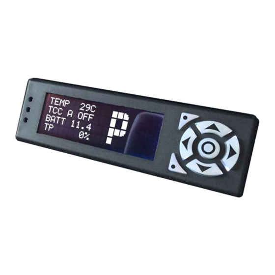
(see page 49) • Shift Pressure Adjustment Screen (see page 50) 4.1.1 Mixed Meter Screen Your COMPUSHIFT II offers a display mode that presents a collection of valuable readouts on one screen. Label Meaning TACH Engine speed in RPM GEAR... -
Page 46: Large Digit Gear Screen
This is not a fault in your COMPUSHIFT II. 4.1.2 Large Digit Gear Screen So you can view key readouts at a glance, the COMPUSHIFT II Display offers large-digit screens, including this one that shows the current transmission gear. -
Page 47: Large Digit Engine Rpm Screen
█ █ █ █ █ █ █ █ ███ ███ ███ So you can view key readouts at a glance, the COMPUSHIFT II Display offers large-digit screens, including this one that displays engine speed in RPM. 4.1.4 Large Digit Vehicle Speed Screen So you can view key readouts at a glance, the COMPUSHIFT II Display offers large-digit screens, including this one that shows the current vehicle speed. -
Page 48: System Setup Menu Screen
(see page 50) You should only enter SETUP mode when it is safe to do so. Do not attempt to setup your COMPUSHIFT II while driving. System Setup Menu... -
Page 49: System Status Screen
COMPUSHIFT II Manual – COMPUSHIFT II Manual 4.1.8 System Status Screen When the system is functioning normally, the "System Status" screen will read "No Faults". If there's a problem, the screen will display a series of messages indicating the nature of the problem(s). If there are multiple faults, this screen will repeatedly cycle through, showing each one for a few seconds. -
Page 50: Shift Pressure Adjustment Screen
4.2 Display SETUP Screens SETUP mode is used to customize your COMPUSHIFT II configuration. You should only enter SETUP mode when it is safe to do so. Do not attempt to setup your COMPUSHIFT II while driving. If you purchased COMPUSHIFT II from a dealer, the dealer has pre-programed your COMPUSHIFT II for your specific application based on a series of questions. -
Page 51: How To Enter Setup Mode
(see page 50) You should only enter SETUP mode when it is safe to do so. Do not attempt to setup your COMPUSHIFT II while driving. System Setup Menu Screens are arranged in a repeating sequence, so if you press the "Next Screen"... -
Page 52: Transmission Type
This means the vehicle is in whatever gear you put the lever, or however you set the Switch-Shift paddles/buttons. In manual mode, COMPUSHIFT II still does pressure modulation and torque converter control -- you have just have to manually change gears. -
Page 53: Number Of Engine Cylinders
4.2.6 Number of Engine Cylinders If you connect a tachometer signal to COMPUSHIFT II (recommended), you need to tell COMPUSHIFT II how many times per engine revolution your tachometer signal fires. The frequency of this signal varies depending on the number and arrangement of engine cylinders. -
Page 54: Throttle Position Sensor Calibration
Before COMPUSHIFT II is properly calibrated, you will see "0.00" as the left-hand and right-hand numbers on the screen. In this situation, the system records both TPS low and TPS high faults until calibration. -
Page 55: Maximum Engine Rpm
As you adjust the shift speed up and down, you may find that the wide-open throttle upshift RPM is different from the speed at which you feel comfortable running your engine. The "Maximum Engine Speed" allows you to set an upper RPM limit or cap at which your COMPUSHIFT II will always upshift. -
Page 56: Final Drive Ratio
When you connect an electronic speedometer to the COMPUSHIFT II speedometer output signal, your speedometer will expect a certain number of pulses per revolution (PPR) of the drive shaft, and you can adjust the PPR with this setting. -
Page 57: Vehicle Weight
TCC mode refers to the torque converter clutch. In previous models of COMPUSHIFT, the TCC was always automatically active, meaning it is preset at the specified MPH and selected gear. COMPUSHIFT II introduces a new mode called "manual mode", in which the TCC is controlled by a switch, either on or off, based on driver input. -
Page 58: Tcc Maximum Throttle
COMPUSHIFT II Manual – COMPUSHIFT II Manual TCC Enable Gear A 4.2.16 TCC Maximum Throttle This setting offers "A" and "B" modes. You can set up two different COMPUSHIFT configurations in advance, and use the mode switch to change between them. -
Page 59: Tcc Enable Speed
COMPUSHIFT II Manual – COMPUSHIFT II Manual If the TCC minimum throttle is set to 0%, you can release the throttle and the TCC will never unlock. This can cause the engine to bog down when the engine gets close to the throttle speed. Setting this to a small number above zero will prevent this. -
Page 60: R2L Pressure Boost
Downshift Offset A 4.2.22 Load Factory Defaults When you change your engine or transmission type via the SETUP screens, COMPUSHIFT II will automatically change the appropriate parameters that are different. But if you need to reset everything, use this function. You will be asked to confirm your decision, since this function has such a large impact. -
Page 61: Advanced Setup
Advanced Setup offers additional screens to fine-tune your COMPUSHIFT II configuration. Adjust these settings with care. If set improperly, you could damage your vehicle or your COMPUSHIFT II. If you have any questions, contact your distributor or HGM headquarters. Button Function Press the "Select"... -
Page 62: Shift Pressure Tables
COMPUSHIFT II Manual – COMPUSHIFT II Manual 4.2.23.1 Shift Pressure Tables This setting offers "A" and "B" modes. You can set up two different COMPUSHIFT configurations in advance, and use the mode switch to change between them. (see page 39) This set of screens lets you adjust the exact transmission pressure that correlate with throttle position. - Page 63 Zoomed-Out View This view shows you the complete table, end-to-end, with a screen for each gear change. For most purposes, this view is sufficient for tuning your COMPUSHIFT II. Button Function Press the Left or Right button to move horizontally inside the table. The horizontal axis represents Throttle Position Percentage.
- Page 64 Important Notes Your table must always have a flat or upwards slope, moving left to right. In other words, COMPUSHIFT II will not all you to set the shift pressure lower than a column that is to the left.
-
Page 65: Shift Speed Tables
COMPUSHIFT II Manual – COMPUSHIFT II Manual 4.2.23.2 Shift Speed Tables This setting offers "A" and "B" modes. You can set up two different COMPUSHIFT configurations in advance, and use the mode switch to change between them. (see page 39) ... - Page 66 Zoomed-Out View This view shows you the complete table, end-to-end, with a screen for each gear change. For most purposes, this view is sufficient for tuning your COMPUSHIFT II. Button Function Press the Left or Right button to move horizontally inside the table. The horizontal axis represents Throttle Position Percentage.
-
Page 67: Tps Direction
Important Notes Your table must always have a flat or upwards slope, moving left to right. In other words, COMPUSHIFT II will not all you to set the shift speed value lower than a column that is to the left. -
Page 68: Tps Ground
COMPUSHIFT II. In that case, your MAP sensor is already grounded, and you should set the MAP Sensor Ground to Off. If you are using a MAP solely for COMPUSHIFT II, then you should set the MAP Sensor Ground to On. -
Page 69: Transmission Temp Sensor Bias
Bias 4.2.23.7 Transmission Temp Sensor Bias This screen allows you to tell COMPUSHIFT II whether or not some other device is providing power to the transmission temperature sensor. In most cases, COMPUSHIFT is the only device reading transmission temperature, so you should leave this setting on. -
Page 70: Display Brightness
Green Blue 100% 4.2.28 System Units Your COMPUSHIFT II can display units in either metric or US standards. The default is US. In metric mode, the measurements change as follows: • Speed is measured in KPH instead of MPH. •... -
Page 71: Contact Information
COMPUSHIFT II Manual – COMPUSHIFT II Manual You can switch between measurement systems without affecting other programming. COMPUSHIFT uses metric units internally. 4.2.29 Contact Information www.compushift.com We've included our phone number and website ( ) in case you have any questions. -
Page 72: Driving & Shifting
When you drive away with light throttle, COMPUSHIFT II upshifts relatively soon. • If you give the engine full throttle, COMPUSHIFT II will upshift at a higher vehicle speed and engine RPM. Shift firmness is controlled in much the same way as shift speed. -
Page 73: Using The A/B Mode Switch (Optional)
COMPUSHIFT II Manual – COMPUSHIFT II Manual 5.3 Using the A/B Mode Switch (Optional) To change between modes, press and hold the button for 2 seconds. It will be illuminated when you are in Mode B. When you start the vehicle, the system will always start in Mode A. -
Page 74: Diagnostics & Troubleshooting
These faults indicate a problem with a control solenoid or wiring in your transmission. • Your COMPUSHIFT II can detect an open circuit or short circuit on the solenoid circuits. It signals any of these conditions by displaying the appropriate fault for the solenoid circuit, called a "driver". -
Page 75: Tps Signal Low
Also, if you reset COMPUSHIFT II using the optional Display, these codes will revert to factory defaults. (As a failsafe, when TPS is not calibrated, COMPUSHIFT II uses a constant value of 50% throttle.) 6.2.5 Transmission Temp Sensor... -
Page 76: Transmission Over Temp
Indicates COMPUSHIFT II detects that the 12-volt power supply has dropped too low for an extended period. • If you have an indication of this fault, make sure your COMPUSHIFT II has a good connection to 12-volt power and ground, and that your battery is fully charged. -
Page 77: System Over Temp
6.2.11 System Over Temp Indicates the internal temperature of COMPUSHIFT II has exceeded a safe range. • COMPUSHIFT II will automatically turn itself off 25 seconds after this fault is displayed. The status LED will go dark. This fault can occur if a partial short exists in the transmission wiring, or if COMPUSHIFT II is overheated due to improper mounting. -
Page 78: Gear Lever Position
COMPUSHIFT II Manual – COMPUSHIFT II Manual 6.3.4 Gear Lever Position This screen displays the current gear lever position. 6.3.5 Transmission Temperature This screen displays the current temperature of the transmission. 6.3.6 Transmission Output Shaft Speed This screen displays the current reading from the TOSS sensor. -
Page 79: Additional Guides & Information
Automatic Transmission Basics (see page 95) 7.1 Changing a Wiring Harness Terminal If you need to change or remove a wire in any of your HGM wiring harness connectors, it is easy to do with the right tool. Contact us to order a terminal remover. -
Page 80: Compushift Ii Quick Install Guide
If it does not release, try giving it more slack from the back - do not tug. If you need to replace wires, you can contact HGM to order additional terminals. We have terminals already connected to pre-cut sections of wire in many different colors. -
Page 81: Typical Installation
Remove the stock pan bolt. Using the provided bolt, install the clamp holding the sensor. Add the spacer between the clamp and the pan if needed. Connect the cable to the sensor and its other end to the TRANS 2 socket on the COMPUSHIFT II controller. Be sure to check for leaks. - Page 82 COMPUSHIFT II Manual – COMPUSHIFT II Manual After locating the line pressure plug, remove it and drill an 11/32" hole through the plug. Then, thread the plug using a 1/8" pipe thread tap. The results should look like the photo to the left. You can now use that plug as an adapter to connect the pressure sensor.
-
Page 83: Installing The Six Shooter Acculink
7.5 Installing the AccuLink Refit Kit 7.5.1 Introduction HGM Automotive Electronics thanks you for upgrading your cable throttle position sensor to the AccuLink TPS system. We believe that great results can be achieved with a very careful installation of the cable operated throttle position sensor. -
Page 84: Removing The Old System
COMPUSHIFT II Manual – COMPUSHIFT II Manual Socket / end-wrench assortment You may also need the following supplies: Insulating tape Wire crimp connectors Wire spade lugs 7.5.4 Removing the Old System Remove the existing cable bracket, cable end, studs, and linkage plates. -
Page 85: Removing The Sensor
COMPUSHIFT II Manual – COMPUSHIFT II Manual 7.5.5 Removing the Sensor Open the sensor box by removing the four case screws and lid. Lift the cable loop from the sensor and push it forward into the cable housing. Using a Phillips screwdriver, remove the two screws holding the sensor. Remove the sensor from the case. -
Page 86: Installing The Acculink Tps
COMPUSHIFT II Manual – COMPUSHIFT II Manual Tighten the Allen set screw. 7.5.7 Installing the AccuLink TPS Begin installation by identifying the ratio arm. The ratio arm is a small oval piece of metal with a protruding stud on its smaller end. -
Page 87: Aligning The Ratio Arm For Edelbrock Afb And Holley Carburetors
COMPUSHIFT II Manual – COMPUSHIFT II Manual 7.5.8 Aligning the Ratio Arm for Edelbrock AFB and Holley Carburetors For Edelbrock AFB and Holley carburetors, set ratio arm angle so that the center of the ratio arm pin is aligned with edge of carburetor linkage as shown above. -
Page 88: Assembling The Tps Bracket
COMPUSHIFT II Manual – COMPUSHIFT II Manual For the Rochester Quadrajet, set the ratio arm angle so that the ratio arm pin is vertical as shown in the picture above. Tighten the screw and nut in this position. 7.5.10 Assembling the TPS Bracket Identify throttle position sensor, sensor bracket, and two 10/32x7/8 Phillips pan-head screws. -
Page 89: Attaching The Tps To The Carburetor
COMPUSHIFT II Manual – COMPUSHIFT II Manual This picture shows the completed sensor and bracket. 7.5.11 Attaching the TPS to the Carburetor Attach the throttle position sensor and bracket assembly to the carburetor using the carburetor's linkage side rear manifold bolt. - Page 90 COMPUSHIFT II Manual – COMPUSHIFT II Manual The position of the sensor bracket must be set to clear the secondary butterfly linkage. This is especially important on the Rochester Quadrajet. Rotate the throttle linkage through its full range of travel to be sure that no part of it hits the throttle position sensor.
-
Page 91: Installing The Adjustable Arm
COMPUSHIFT II Manual – COMPUSHIFT II Manual 7.5.12 Installing the Adjustable Arm The adjustable arm is made of two pieces: the fixed, threaded section and the sliding section. Identify and assemble the adjustable arm, leaving the screws gently snug. Attach the fixed section of the adjustable arm to the ratio arm. -
Page 92: Checking The Adjustable Arm And Sensor
COMPUSHIFT II Manual – COMPUSHIFT II Manual Attach the adjustable arm by rotating the throttle position sensor so that its pin can be inserted into the adjustable arm. The picture above shows the arm in its fully installed position. Do not lubricate the linkage. The AccuLink system is designed to work WITHOUT lubrication. Most lubricants will attract dirt, shortening the life of the system. -
Page 93: Connecting The Tps
COMPUSHIFT II Manual – COMPUSHIFT II Manual 7.5.14 Connecting the TPS Install throttle position sensor plug into throttle position sensor. The plug has a rubber gasket that is tight fitting. Be sure to push the plug into the socket by squeezing the plug and the sensor together as shown so as not to bend the sensor bracket. -
Page 94: Securing The Tps Wiring Harness
The gear lever position sensor for the ZF4HP-24 transmission comes in two varieties; US and UK. The US version of the sensor has 5(five) wires that need to be processed by COMPUSHIFT II and the UK version has 4(four) wires. -
Page 95: Automatic Transmission Basics
BLUE/BLACK, and WHITE connects to BLUE. 7.7 Automatic Transmission Basics In using COMPUSHIFT II, it's helpful to understand how your automatic transmission works. This section gives a simplified overview of a typical automatic transmission. The major components in your transmission include: •... -
Page 96: Specifications & Pinouts
(see page 162) • Warranty (see page 170) 8.1 Controller Mechanical Drawings For vehicle and powertrain integrators, HGM publishes solid models of the CS2 controller. Please choose from the following: • CS2 Solid Model (STEP format) • CS2 Solid Model (IGES format) 8.2 Controller Specifications... -
Page 97: Chassis
COMPUSHIFT II Manual – COMPUSHIFT II Manual 8.2.1.3 Chassis • Chassis is a factory-sealed black powder-coated aluminum box with mounting flanges. There are no user- serviceable parts inside. The chassis should not be opened. • Dimensions • 4.875 x 6.375 x 2.125″ (excluding mounting flanges) •... -
Page 98: Connectors
COMPUSHIFT II Manual – COMPUSHIFT II Manual • Automatic calibration to stroke range • 5 volt reference signal provided • Dual CAN buses for connection to vehicle networking 8.2.1.7 Connectors • Power – connection to vehicle power • Engine – connection to throttle position sensor, tachometer, speedometer, MAP sensor •... -
Page 99: Environmental Requirements
• Normal automotive environment. The display should not be dropped. 8.3.1.6 Electrical Specifications • All electrical power is provided by the COMPUSHIFT II controller • Connection is provided via a standard 4-pin connector and 2 meter (6 foot) cable. •... -
Page 100: Advanced Setup Features
COMPUSHIFT II Manual – COMPUSHIFT II Manual 8.3.1.10 Advanced Setup Features • The display allows use of an extended set of programming features, including but not limited to: • Transmission Type Selection • Transmission Shift Mode Selection • Torque Converter Clutch Parameters •... -
Page 101: Cable Tps Specifications
COMPUSHIFT II Manual – COMPUSHIFT II Manual 8.5 Cable TPS Specifications 8.5.1 Type • Cable-actuated, sealed variable resistor with spring preload 8.5.2 Chassis • Chassis is a black powder-coated aluminum box with mounting flanges. The throttle cable exits one side of the box. -
Page 102: Pinouts For Engine Connector
COMPUSHIFT II Manual – COMPUSHIFT II Manual • Pinouts for Ford AODE (see page 128) • Pinouts for Ford E4OD (see page 135) • Pinouts for GM 4L60E and 4L80E (see page 142) • Pinouts for Toyota A442F (see page 149) •... - Page 103 COMPUSHIFT II Manual – COMPUSHIFT II Manual CONNECT PIN NAME FUNCTION WIRE TERMINATION NOTE COLOR ENGINE MAP RETURN ENGINE ENGINE TEMP ENGINE CAN1 + CAN BUS HIGH SIGNAL ENGINE ENGINE TOSS OUT ADJUSTABLE PPL/WHT FLYING LEAD REPRO SPEEDOMETER OUTPUT ENGINE...
-
Page 104: Pinouts For Option Connector
COMPUSHIFT II Manual – COMPUSHIFT II Manual CONNECT PIN NAME FUNCTION WIRE TERMINATION NOTE COLOR ENGINE ENGINE TEMP RETURN ENGINE CAN1 - CAN BUS LOW SIGNAL ENGINE 8.6.2 Pinouts for Option Connector 8.6.2.1 OPTIONS Connector Note: This is the view into the receptacle on controller, not the plug. - Page 105 COMPUSHIFT II Manual – COMPUSHIFT II Manual CONNEC NAME FUNCTION WIRE TERMINATI NOTES COLOR OPTIONS CONNECTION OPTIONS CONNECTION OPTIONS CONNECTION OPTIONS SOLENOID 12 REVERSE Must drive relay, LAMP RELAY not lamps directly. OPTIONS SOLENOID 11 NEUTRAL Not available on START RELAY...
-
Page 106: Pinouts For Ford 4R70W - Black Plug
COMPUSHIFT II Manual – COMPUSHIFT II Manual CONNEC NAME FUNCTION WIRE TERMINATI NOTES COLOR OPTIONS CALIBRATION INDICATOR 1 OPTIONS CALIBRATION SELECT 2 OPTIONS CALIBRATION INDICATOR 2 OPTIONS TCC MANUAL TURNS ON BLU/OR TO SWITCH SWITCH TO GND ENGAGE OPTIONS TCC LOCKUP... - Page 107 COMPUSHIFT II Manual – COMPUSHIFT II Manual CONNECT PIN # PIN NAME FUNCTION WIRE TERMINATIO NOTES COLOR TRANS 1 +12V POWER 12VDC RED 18GA TRANS PLUG SOLENOIDS PIN 3 TRANS 1 +12V POWER CONNECTIO TRANS 1 +5V POWER CONNECTIO TRANS 1...
- Page 108 COMPUSHIFT II Manual – COMPUSHIFT II Manual CONNECT PIN # PIN NAME FUNCTION WIRE TERMINATIO NOTES COLOR TRANS 1 SOLENOID 5 BLU/YEL TRANS PLUG CONTROL PIN 7 SIDE TRANS 1 SOLENOID 6 YEL/BLU TRANS PLUG CONTROL PIN 6 SIDE TRANS 1...
-
Page 109: Engine Connector
COMPUSHIFT II Manual – COMPUSHIFT II Manual CONNECT PIN # PIN NAME FUNCTION WIRE TERMINATIO NOTES COLOR TRANS 1 DIGITAL SHIFT LEVER 4 CONNECTIO TRANS 1 DIGITAL SHIFT LEVER 5 CONNECTIO TRANS 1 TRANSFER TRANSFER YELLOW OUT OF LOOM FLYING LEAD ... - Page 110 COMPUSHIFT II Manual – COMPUSHIFT II Manual CONNECT PIN NAME FUNCTION WIRE TERMINATION NOTE COLOR ENGINE TPS RETURN TPS GND GRN/WHT TPS TERMINAL ENGINE ENGINE MAP SIGNAL ENGINE MAP RETURN ENGINE ENGINE TEMP ENGINE CAN1 + CAN BUS HIGH SIGNAL...
-
Page 111: Options Connector
COMPUSHIFT II Manual – COMPUSHIFT II Manual CONNECT PIN NAME FUNCTION WIRE TERMINATION NOTE COLOR ENGINE SWITCH SHIFT SHIFT UP WHT/RED FLYING LEAD ENGINE SWITCH SHIFT GND OR COMMON WHT/RED FLYING LEAD ENGINE SWITCH DOWN SHIFT DOWN WHT/BLK FLYING LEAD... - Page 112 COMPUSHIFT II Manual – COMPUSHIFT II Manual CONNEC NAME FUNCTION WIRE TERMINATI NOTES COLOR OPTIONS CAN2+ CAN BUS 2 HIGH SIGNAL OPTIONS RS232 TX DISPLAY DISPLAY PLUG OPTIONS LIN DATA COMMUNICATI OPTIONS CONNECTION OPTIONS CONNECTION OPTIONS CONNECTION OPTIONS SOLENOID 12...
- Page 113 COMPUSHIFT II Manual – COMPUSHIFT II Manual CONNEC NAME FUNCTION WIRE TERMINATI NOTES COLOR OPTIONS CAN2- CAN BUS 2 LOW SIGNAL OPTIONS RS232 RX DISPLAY GREEN DISPLAY PLUG OPTIONS CALIBRATION SELECT 1 OPTIONS CALIBRATION INDICATOR 1 OPTIONS CALIBRATION SELECT 2...
-
Page 114: Pinouts For Ford 4R70W - White Plug
COMPUSHIFT II Manual – COMPUSHIFT II Manual 8.6.4 Pinouts for Ford 4R70W - White Plug 8.6.4.1 TRANS 1 Connector Note: This is the view into the receptacle on controller, not the plug. CONNECT PIN # PIN NAME FUNCTION WIRE TERMINATIO... - Page 115 COMPUSHIFT II Manual – COMPUSHIFT II Manual CONNECT PIN # PIN NAME FUNCTION WIRE TERMINATIO NOTES COLOR TRANS 1 SOLENOID 2 GRN/WHT TRANS PLUG CONTROL PIN 3 SIDE TRANS 1 SOLENOID 3 CONNECTIO TRANS 1 SOLENOID 4 CONNECTIO TRANS 1...
-
Page 116: Engine Connector
COMPUSHIFT II Manual – COMPUSHIFT II Manual CONNECT PIN # PIN NAME FUNCTION WIRE TERMINATIO NOTES COLOR TRANS 1 TOSS INPUT TOSS LOW TOSS PIN B WEATHERPAC K 2PIN FEM TRANS 1 DIGITAL SHIFT RANGE BLU/R 4 WAY PIN A... - Page 117 COMPUSHIFT II Manual – COMPUSHIFT II Manual CONNECT PIN NAME FUNCTION WIRE TERMINATION NOTE COLOR ENGINE TACH SIG IN INPUT RPM SIG FLYING LEAD ENGINE ENGINE ENGINE TPS 5 VOLT GRN/RED TPS TERMINAL SUPPLY ENGINE TPS SIGNAL TPS SIGNAL TPS TERMINAL...
-
Page 118: Options Connector
COMPUSHIFT II Manual – COMPUSHIFT II Manual CONNECT PIN NAME FUNCTION WIRE TERMINATION NOTE COLOR ENGINE MODE MODE A/B SWITCH BLUE/OR FLYING LEAD ENGINE MODE SWITCH SWITCH LED ON/ FLYING LEAD ENGINE OD ON/OFF LED TO LED ON BLU/RED FLYING LEAD... - Page 119 COMPUSHIFT II Manual – COMPUSHIFT II Manual Note: This is the view into the receptacle on controller, not the plug. CONNEC NAME FUNCTION WIRE TERMINATI NOTES COLOR OPTIONS 12 V 12 VOLT OUT OPTIONS 5 VOLT YELLOW DISPLAY DISPLAY PLUG...
- Page 120 COMPUSHIFT II Manual – COMPUSHIFT II Manual CONNEC NAME FUNCTION WIRE TERMINATI NOTES COLOR OPTIONS OPTIONS GND DISPLAY BLACK DISPLAY PLUG OPTIONS CAN2- CAN BUS 2 LOW SIGNAL OPTIONS RS232 RX DISPLAY GREEN DISPLAY PLUG OPTIONS CALIBRATION SELECT 1 OPTIONS...
- Page 121 COMPUSHIFT II Manual – COMPUSHIFT II Manual 8.6.5 Pinouts for Ford 4R100 8.6.5.1 TRANS 1 Connector Note: This is the view into the receptacle on controller, not the plug. CONNECT PIN NAME FUNCTION WIRE TERMINATIO NOTES COLOR TRANS 1 +12V POWER...
- Page 122 COMPUSHIFT II Manual – COMPUSHIFT II Manual CONNECT PIN NAME FUNCTION WIRE TERMINATIO NOTES COLOR TRANS 1 SOLENOID 3 COAST TRANS PLUG CLUTCH PIN 5 TRANS 1 SOLENOID 4 CONNECTIO TRANS 1 SOLENOID 5 BLU/YEL TRANS PLUG CONTROL PIN 2...
- Page 123 COMPUSHIFT II Manual – COMPUSHIFT II Manual CONNECT PIN NAME FUNCTION WIRE TERMINATIO NOTES COLOR TRANS 1 DIGITAL SHIFT RANGE BLU/RED 4 WAY PIN A WEATHERPAC LEVER 1 SENSOR A K 4PIN TRANS 1 DIGITAL SHIFT RANGE BLU/BLK 4 WAY PIN B...
- Page 124 COMPUSHIFT II Manual – COMPUSHIFT II Manual CONNECT PIN NAME FUNCTION WIRE TERMINATION NOTE COLOR ENGINE ENGINE ENGINE TPS 5 VOLT GRN/RED TPS TERMINAL SUPPLY ENGINE TPS SIGNAL TPS SIGNAL TPS TERMINAL ENGINE TPS RETURN TPS GND GRN/WHT TPS TERMINAL...
- Page 125 COMPUSHIFT II Manual – COMPUSHIFT II Manual CONNECT PIN NAME FUNCTION WIRE TERMINATION NOTE COLOR ENGINE MODE SWITCH SWITCH LED ON/ FLYING LEAD ENGINE OD ON/OFF LED TO LED ON BLU/RED FLYING LEAD SWITCH ENGINE OD CANCEL SWITCH INPUT TO...
- Page 126 COMPUSHIFT II Manual – COMPUSHIFT II Manual CONNEC NAME FUNCTION WIRE TERMINATI NOTES COLOR OPTIONS 12 V 12 VOLT OUT OPTIONS 5 VOLT YELLOW DISPLAY DISPLAY PLUG OPTIONS CAN2+ CAN BUS 2 HIGH SIGNAL OPTIONS RS232 TX DISPLAY DISPLAY PLUG...
- Page 127 COMPUSHIFT II Manual – COMPUSHIFT II Manual CONNEC NAME FUNCTION WIRE TERMINATI NOTES COLOR OPTIONS OPTIONS GND DISPLAY BLACK DISPLAY PLUG OPTIONS CAN2- CAN BUS 2 LOW SIGNAL OPTIONS RS232 RX DISPLAY GREEN DISPLAY PLUG OPTIONS CALIBRATION SELECT 1 OPTIONS...
- Page 128 COMPUSHIFT II Manual – COMPUSHIFT II Manual 8.6.6 Pinouts for Ford AODE 8.6.6.1 TRANS 1 Connector Note: This is the view into the receptacle on controller, not the plug. CONNECT NAME FUNCTION WIRE TERMINATIO NOTES COLOR TRANS 1 +12V POWER 12VDC RED ...
- Page 129 COMPUSHIFT II Manual – COMPUSHIFT II Manual CONNECT NAME FUNCTION WIRE TERMINATIO NOTES COLOR TRANS 1 SOLENOID 2 TCC CONTROL GRN/WHT TRANS PLUG SIDE PIN 3 TRANS 1 SOLENOID 3 CONNECTION TRANS 1 SOLENOID 4 CONNECTION TRANS 1 SOLENOID 5...
- Page 130 COMPUSHIFT II Manual – COMPUSHIFT II Manual CONNECT NAME FUNCTION WIRE TERMINATIO NOTES COLOR TRANS 1 DIGITAL SHIFT LEVER 2 CONNECTION TRANS 1 DIGITAL SHIFT LEVER 3 CONNECTION TRANS 1 DIGITAL SHIFT LEVER 4 CONNECTION TRANS 1 DIGITAL SHIFT LEVER 5...
- Page 131 COMPUSHIFT II Manual – COMPUSHIFT II Manual CONNECT PIN NAME FUNCTION WIRE TERMINATION NOTE COLOR ENGINE TPS 5 VOLT GRN/RED TPS TERMINAL SUPPLY ENGINE TPS SIGNAL TPS SIGNAL TPS TERMINAL ENGINE TPS RETURN TPS GND GRN/WHT TPS TERMINAL ENGINE ENGINE...
- Page 132 COMPUSHIFT II Manual – COMPUSHIFT II Manual CONNECT PIN NAME FUNCTION WIRE TERMINATION NOTE COLOR ENGINE OD ON/OFF LED TO LED ON BLU/RED FLYING LEAD SWITCH ENGINE OD CANCEL SWITCH INPUT TO BLU/YEL FLYING LEAD SWITCH ENGINE SWITCH SHIFT SHIFT UP...
- Page 133 COMPUSHIFT II Manual – COMPUSHIFT II Manual CONNEC NAME FUNCTION WIRE TERMINATI NOTES COLOR OPTIONS 12 V 12 VOLT OUT OPTIONS 5 VOLT YELLOW DISPLAY DISPLAY PLUG OPTIONS CAN2+ CAN BUS 2 HIGH SIGNAL OPTIONS RS232 TX DISPLAY DISPLAY PLUG...
- Page 134 COMPUSHIFT II Manual – COMPUSHIFT II Manual CONNEC NAME FUNCTION WIRE TERMINATI NOTES COLOR OPTIONS OPTIONS GND DISPLAY BLACK DISPLAY PLUG OPTIONS CAN2- CAN BUS 2 LOW SIGNAL OPTIONS RS232 RX DISPLAY GREEN DISPLAY PLUG OPTIONS CALIBRATION SELECT 1 OPTIONS...
- Page 135 COMPUSHIFT II Manual – COMPUSHIFT II Manual 8.6.7 Pinouts for Ford E4OD 8.6.7.1 TRANS 1 Connector Note: This is the view into the receptacle on controller, not the plug. CONNECT PIN NAME FUNCTION WIRE TERMINATIO NOTES COLOR TRANS 1 +12V POWER...
- Page 136 COMPUSHIFT II Manual – COMPUSHIFT II Manual CONNECT PIN NAME FUNCTION WIRE TERMINATIO NOTES COLOR TRANS 1 SOLENOID 3 COAST TRANS PLUG CLUTCH PIN 5 TRANS 1 SOLENOID 4 CONNECTION TRANS 1 SOLENOID 5 SS2 CONTROL BLU/YEL TRANS PLUG SIDE...
- Page 137 COMPUSHIFT II Manual – COMPUSHIFT II Manual CONNECT PIN NAME FUNCTION WIRE TERMINATIO NOTES COLOR TRANS 1 DIGITAL SHIFT LEVER 3 CONNECTION TRANS 1 DIGITAL SHIFT LEVER 4 CONNECTION TRANS 1 DIGITAL SHIFT LEVER 5 CONNECTION TRANS 1 TRANSFER TRANSFER...
- Page 138 COMPUSHIFT II Manual – COMPUSHIFT II Manual CONNECT PIN NAME FUNCTION WIRE TERMINATION NOTE COLOR ENGINE TPS SIGNAL TPS SIGNAL TPS TERMINAL ENGINE TPS RETURN TPS GND GRN/WHT TPS TERMINAL ENGINE ENGINE MAP SIGNAL ENGINE MAP RETURN ENGINE ENGINE TEMP...
- Page 139 COMPUSHIFT II Manual – COMPUSHIFT II Manual CONNECT PIN NAME FUNCTION WIRE TERMINATION NOTE COLOR ENGINE OD CANCEL SWITCH INPUT TO BLU/YEL FLYING LEAD SWITCH ENGINE SWITCH SHIFT SHIFT UP WHT/RED FLYING LEAD ENGINE SWITCH SHIFT GND OR COMMON WHT/RED...
- Page 140 COMPUSHIFT II Manual – COMPUSHIFT II Manual CONNEC NAME FUNCTION WIRE TERMINATI NOTES COLOR OPTIONS 5 VOLT YELLOW DISPLAY DISPLAY PLUG OPTIONS CAN2+ CAN BUS 2 HIGH SIGNAL OPTIONS RS232 TX DISPLAY DISPLAY PLUG OPTIONS LIN DATA COMMUNICATI OPTIONS CONNECTION...
- Page 141 COMPUSHIFT II Manual – COMPUSHIFT II Manual CONNEC NAME FUNCTION WIRE TERMINATI NOTES COLOR OPTIONS GND DISPLAY BLACK DISPLAY PLUG OPTIONS CAN2- CAN BUS 2 LOW SIGNAL OPTIONS RS232 RX DISPLAY GREEN DISPLAY PLUG OPTIONS CALIBRATION SELECT 1 OPTIONS CALIBRATION...
- Page 142 COMPUSHIFT II Manual – COMPUSHIFT II Manual 8.6.8 Pinouts for GM 4L60E and 4L80E 8.6.8.1 TRANS 1 Connector Note: This is the view into the receptacle on controller, not the plug. CONNECT PIN NAME FUNCTION WIRE TERMINATIO NOTES COLOR TRANS 1...
- Page 143 COMPUSHIFT II Manual – COMPUSHIFT II Manual CONNECT PIN NAME FUNCTION WIRE TERMINATIO NOTES COLOR TRANS 1 SOLENOID 3 TCC 4L80E GRN/WHT TRANS PLUG PIN S TRANS 1 SOLENOID 4 TCC 4L60E TRANS PLUG PIN T TRANS 1 SOLENOID 5...
- Page 144 COMPUSHIFT II Manual – COMPUSHIFT II Manual CONNECT PIN NAME FUNCTION WIRE TERMINATIO NOTES COLOR TRANS 1 DIGITAL SHIFT PSM C TRANS PLUG LEVER 3 PIN P TRANS 1 DIGITAL SHIFT LEVER 4 CONNECTION TRANS 1 DIGITAL SHIFT LEVER 5...
- Page 145 COMPUSHIFT II Manual – COMPUSHIFT II Manual CONNECT PIN NAME FUNCTION WIRE TERMINATION NOTE COLOR ENGINE TPS SIGNAL TPS SIGNAL TPS TERMINAL ENGINE TPS RETURN TPS GND GRN/WHT TPS TERMINAL ENGINE ENGINE MAP SIGNAL ENGINE MAP RETURN ENGINE ENGINE TEMP...
- Page 146 COMPUSHIFT II Manual – COMPUSHIFT II Manual CONNECT PIN NAME FUNCTION WIRE TERMINATION NOTE COLOR ENGINE OD CANCEL SWITCH INPUT TO BLU/YEL FLYING LEAD SWITCH ENGINE SWITCH SHIFT SHIFT UP WHT/RED FLYING LEAD ENGINE SWITCH SHIFT GND OR COMMON WHT/RED...
- Page 147 COMPUSHIFT II Manual – COMPUSHIFT II Manual CONNEC NAME FUNCTION WIRE TERMINATI NOTES COLOR OPTIONS 5 VOLT YELLOW DISPLAY DISPLAY PLUG OPTIONS CAN2+ CAN BUS 2 HIGH SIGNAL OPTIONS RS232 TX DISPLAY DISPLAY PLUG OPTIONS LIN DATA COMMUNICATI OPTIONS CONNECTION...
- Page 148 COMPUSHIFT II Manual – COMPUSHIFT II Manual CONNEC NAME FUNCTION WIRE TERMINATI NOTES COLOR OPTIONS GND DISPLAY BLACK DISPLAY PLUG OPTIONS CAN2- CAN BUS 2 LOW SIGNAL OPTIONS RS232 RX DISPLAY GREEN DISPLAY PLUG OPTIONS CALIBRATION SELECT 1 OPTIONS CALIBRATION...
- Page 149 COMPUSHIFT II Manual – COMPUSHIFT II Manual 8.6.9 Pinouts for Toyota A442F 8.6.9.1 TRANS 1 Connector Note: This is the view into the receptacle on controller, not the plug. CONNEC PIN NAME FUNCTIO WIRE TERMINATIO TO LOOM TRANS COLOR N IN PLUG...
- Page 150 COMPUSHIFT II Manual – COMPUSHIFT II Manual CONNEC PIN NAME FUNCTIO WIRE TERMINATIO TO LOOM TRANS COLOR N IN PLUG PLUG TERM LOOM COLOR TRANS 1 MLPS BLK 20GA SHIFT LEVER MLPS PIN 7 RED/BLU PLUG PIN A TRANS 1...
- Page 151 COMPUSHIFT II Manual – COMPUSHIFT II Manual CONNEC PIN PIN NAME FUNCTI WIRE TERMINATIO TO LOOM TRANS COLOR N IN PLUG PLUG TERM LOOM COLOR TRANS 2 TRANS 2 SPEED INPUT TRANS 2 SHIFT LEV NEUTRA LT/BLU SHIFT LEVER MLPS PIN 3...
- Page 152 COMPUSHIFT II Manual – COMPUSHIFT II Manual CONNECT PIN NAME FUNCTION WIRE TERMINATION NOTE COLOR ENGINE ENGINE MAP SIGNAL ENGINE MAP RETURN ENGINE ENGINE TEMP ENGINE CAN1 + CAN BUS HIGH SIGNAL ENGINE ENGINE TOSS OUT ADJUSTABLE PPL/WHT FLYING LEAD...
- Page 153 COMPUSHIFT II Manual – COMPUSHIFT II Manual CONNECT PIN NAME FUNCTION WIRE TERMINATION NOTE COLOR ENGINE SWITCH SHIFT GND OR COMMON WHT/RED FLYING LEAD ENGINE SWITCH DOWN SHIFT DOWN WHT/BLK FLYING LEAD ENGINE ENGINE TEMP RETURN ENGINE CAN1 - CAN BUS LOW...
- Page 154 COMPUSHIFT II Manual – COMPUSHIFT II Manual CONNEC NAME FUNCTION WIRE TERMINATI NOTES COLOR OPTIONS RS232 TX DISPLAY DISPLAY PLUG OPTIONS LIN DATA COMMUNICATI OPTIONS CONNECTION OPTIONS CONNECTION OPTIONS CONNECTION OPTIONS SOLENOID 12 REVERSE Must drive relay, LAMP RELAY not lamps directly.
- Page 155 COMPUSHIFT II Manual – COMPUSHIFT II Manual CONNEC NAME FUNCTION WIRE TERMINATI NOTES COLOR OPTIONS RS232 RX DISPLAY GREEN DISPLAY PLUG OPTIONS CALIBRATION SELECT 1 OPTIONS CALIBRATION INDICATOR 1 OPTIONS CALIBRATION SELECT 2 OPTIONS CALIBRATION INDICATOR 2 OPTIONS TCC MANUAL...
- Page 156 COMPUSHIFT II Manual – COMPUSHIFT II Manual Note: This is the view into the receptacle on controller, not the plug. CONNECT PIN NAME FUNCTION WIRE TERMINATIO NOTES COLOR TRANS 1 +12V POWER 12VDC RED/BLK TRANS PLUG SOLENOIDS 18GA PIN M...
- Page 157 COMPUSHIFT II Manual – COMPUSHIFT II Manual CONNECT PIN NAME FUNCTION WIRE TERMINATIO NOTES COLOR TRANS 1 SOLENOID 6 YEL/BLU TRANS PLUG CONTROL PIN H SIDE TRANS 1 DRS GND 5 WAY PLUG TO SWITCH PIN D COM-BRN/PPL TRANS 1...
- Page 158 COMPUSHIFT II Manual – COMPUSHIFT II Manual CONNECT PIN NAME FUNCTION WIRE TERMINATIO NOTES COLOR TRANS 1 DIGITAL SHIFT LEVER 5 TRANS 1 TRANSFER CASE 1 8.6.10.2 ENGINE Connector Note: This is the view into the receptacle on controller, not the plug.
- Page 159 COMPUSHIFT II Manual – COMPUSHIFT II Manual CONNECT PIN NAME FUNCTION WIRE TERMINATION NOTE COLOR ENGINE ENGINE MAP SIGNAL ENGINE MAP RETURN ENGINE ENGINE TEMP ENGINE CAN1 + CAN BUS HIGH SIGNAL ENGINE ENGINE TOSS OUT ADJUSTABLE PPL/WHT FLYING LEAD...
- Page 160 COMPUSHIFT II Manual – COMPUSHIFT II Manual CONNECT PIN NAME FUNCTION WIRE TERMINATION NOTE COLOR ENGINE SWITCH SHIFT GND OR COMMON WHT/RED FLYING LEAD ENGINE SWITCH DOWN SHIFT DOWN WHT/BLK FLYING LEAD ENGINE ENGINE TEMP RETURN ENGINE CAN1 - CAN BUS LOW...
- Page 161 COMPUSHIFT II Manual – COMPUSHIFT II Manual CONNEC NAME FUNCTION WIRE TERMINATI NOTES COLOR OPTIONS RS232 TX DISPLAY DISPLAY PLUG OPTIONS LIN DATA COMMUNICATI OPTIONS CONNECTION OPTIONS CONNECTION OPTIONS CONNECTION OPTIONS SOLENOID 12 REVERSE Must drive relay, LAMP RELAY not lamps directly.
- Page 162 COMPUSHIFT II Manual – COMPUSHIFT II Manual CONNEC NAME FUNCTION WIRE TERMINATI NOTES COLOR OPTIONS RS232 RX DISPLAY GREEN DISPLAY PLUG OPTIONS CALIBRATION SELECT 1 OPTIONS CALIBRATION INDICATOR 1 OPTIONS CALIBRATION SELECT 2 OPTIONS CALIBRATION INDICATOR 2 OPTIONS TCC MANUAL...
- Page 163 COMPUSHIFT II Manual – COMPUSHIFT II Manual Abbreviation Connector Auxiliary transmission connector TISS Transmission input speed sensor TOSS Transmission output speed sensor MLPS Manual lever position switch (side of transmissino) Shift Lever body connector Shift lever Indicator (bezel) 8.6.11.2 TRANS 1 Connector Note: This is the view into the receptacle on controller, not the plug.
- Page 164 COMPUSHIFT II Manual – COMPUSHIFT II Manual CONNECTOR TERMINATIO WIRE COLOR FUNCTION NOTES TRANS 1 MAIN-03 Black Solenoid Ground for Or TRANS 2 B8 TRANS 1 MAIN-04 Black Solenoid Ground for Or TRANS 2 B8 TRANS 1 AUX-04 Black Solenoid Ground for...
- Page 165 COMPUSHIFT II Manual – COMPUSHIFT II Manual CONNECTOR TERMINATION WIRE COLOR FUNCTION NOTES TRANS 2 FLYING LEAD Yellow / Red Engine Torque Modulation TRANS 2 MAIN-06 Blue / White Solenoid SR TRANS 2 MAIN-14 Purple Solenoid S4 TRANS 2 MAIN-07...
- Page 166 COMPUSHIFT II Manual – COMPUSHIFT II Manual CONNECT PIN NAME FUNCTION WIRE TERMINATION NOTE COLOR ENGINE TPS 5 VOLT GRN/RED TPS TERMINAL SUPPLY ENGINE TPS SIGNAL TPS SIGNAL TPS TERMINAL ENGINE TPS RETURN TPS GND GRN/WHT TPS TERMINAL ENGINE ENGINE...
- Page 167 COMPUSHIFT II Manual – COMPUSHIFT II Manual CONNECT PIN NAME FUNCTION WIRE TERMINATION NOTE COLOR ENGINE OD ON/OFF LED TO LED ON BLU/RED FLYING LEAD SWITCH ENGINE OD CANCEL SWITCH INPUT TO BLU/YEL FLYING LEAD SWITCH ENGINE SWITCH SHIFT SHIFT UP...
- Page 168 COMPUSHIFT II Manual – COMPUSHIFT II Manual OPTIONS Connector Note: This is the view into the receptacle on controller, not the plug. CONNEC NAME FUNCTION WIRE TERMINATI NOTES COLOR OPTIONS 12 V 12 VOLT OUT OPTIONS 5 VOLT YELLOW DISPLAY...
- Page 169 COMPUSHIFT II Manual – COMPUSHIFT II Manual CONNEC NAME FUNCTION WIRE TERMINATI NOTES COLOR OPTIONS SOLENOID 11 NEUTRAL Not available on START RELAY GM 4L80E, GM 4L60E, GM 4L65E OPTIONS SOLENOID 10 OPTIONS SOLENOID 9 OPTIONS OPTIONS GND DISPLAY BLACK...
- Page 170 8.7 Warranty For a period of one (1) year after purchase, HGM Automotive Electronics will repair or replace, at our expense and option, any COMPUSHIFT II component that in normal use has proven to be defective in workmanship or material.
Need help?
Do you have a question about the COMPUSHIFT II and is the answer not in the manual?
Questions and answers