Sign In
Upload
Manuals
Brands
HGM Manuals
Controller
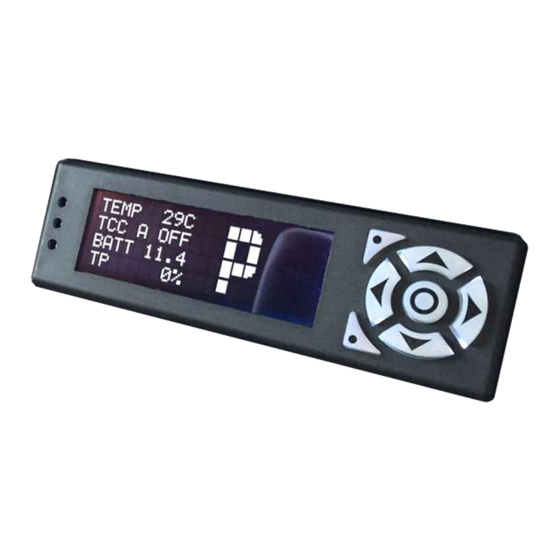
COMPUSHIFT II
User Manuals: HGM COMPUSHIFT II Transmission Controller
Manuals and User Guides for HGM COMPUSHIFT II Transmission Controller. We have
1
HGM COMPUSHIFT II Transmission Controller manual available for free PDF download: Manual
HGM COMPUSHIFT II Manual (170 pages)
Brand:
HGM
| Category:
Controller
| Size: 10 MB
Table of Contents
Table of Contents
2
1 Preparing for Your Installation
12
Engine Preparation
12
Transmission Preparation
12
Additional Planning
12
Other Considerations
13
Tools You will Need
13
Tools You May Need
13
Installation Notes for GM 4L80E / 4L60E Series
14
Transmission Output Shaft Speed (TOSS) Sensor
14
Transmission Main Plug
14
Installation Notes for Ford AODE / 4R70W / 4R100 / E4OD
14
2 Unpacking & Inspecting Your Kit
16
The COMPUSHIFT II Controller
16
The Display
16
Transmission Wiring Harness
17
Power & Engine Wiring Harness
18
Hydraulic Pressure Sensor Harness (Optional)
18
Switch-Shift Harness
19
The Acculink TPS (Optional)
19
The TPS Connector for an Electronic Fuel Injection (Optional)
20
For an Electronic Fuel Injection Engine with a Standard GM TPS
20
For Other Types of Electronic Fuel Injection Engines
21
Cable Operated Throttle Position Sensor (Optional)
21
3 Installation
22
Mount the Controller
22
Install the Transmission Harness
22
Connect the Main Transmission Plug
23
Connect to the TOSS Sensor
23
Installation
23
TOSS Locations for Different Transmissions
24
Connect the Lever Sensor Connector, if Applicable
24
Connect to the Reproduced TOSS Signal
25
Connect the Transfer Case Calculation Wire (4WD)
25
Install the Power & Engine Harness
25
Connect the Throttle Position Sensor
26
Connect the Power and Meter Leads
26
Connect the Switch-Shift Harness
27
Connect the Overdrive Cancel Switch and Indicator
27
CAN Bus Connector
27
Install or Connect a Throttle Position Sensor
27
Install the Acculink TPS (Optional)
27
Find the Acculink TPS Parts
28
Assemble the Acculink TPS and Bracket
28
Assemble and Install the Ratio Arm
29
Align the Ratio Arm
29
Assemble the Adjustable Arm
30
Attach the Throttle Position Sensor
30
Set the Adjustable Arm Length
31
Install the Adjustable Arm
31
Check the Adjustable Arm & TPS
31
Check the Linkage
32
Connect the Acculink TPS to the Harness
33
Secure the Wiring Harness to the Acculink TPS
34
Install the Cable-Operated TPS (Optional)
34
Install the Cable TPS
34
Mount the Cable Bracket
35
Mount the Sensor Box
35
Install the EFI TPS Adapter Harness (Optional)
36
EFI with a General Motors Throttle Position Sensor
36
Other Systems
36
Install the Switch-Shift Wiring Harness (Optional)
37
Connect the Three (3) Leads
38
Connect to the Power & Engine Harness
38
Install the A-B Mode Switch (Optional)
39
Installing the Switch
39
Using the Switch
39
SETUP Screens
40
Install the Overdrive Cancel Switch (Optional)
40
Installing the Switch
40
Using the Switch
41
Install the Manual TCC Switch (Optional)
41
Installing the Switch
41
Using the Switch
42
Connect the Display
42
Checkout and Testing
42
Final Checks
42
Calibrate the Throttle Position Sensor
42
4 Monitoring & Tuning Your System
44
Display DASHBOARD Screens
45
Mixed Meter Screen
45
Large Digit Gear Screen
46
Large Digit Engine RPM Screen
47
Large Digit Vehicle Speed Screen
47
Large Digit Transmission Temperature Screen
47
Stopwatch Screen
47
System Setup Menu Screen
48
System Status Screen
49
Shift Speed Adjust Screen
49
Shift Pressure Adjustment Screen
50
Display SETUP Screens
50
How SETUP Screens Work
50
How to Enter SETUP Mode
51
Transmission Type
52
Engine Type
52
Shift Mode
52
Number of Engine Cylinders
53
Throttle Position Sensor Calibration
54
Maximum Engine RPM
55
Transfer Case Ratio
55
Final Drive Ratio
56
Speedometer Calibration
56
Tire Diameter
56
Vehicle Weight
57
TCC Mode
57
TCC Enable Gear
57
TCC Maximum Throttle
58
TCC Minimum Throttle
58
TCC Enable Speed
59
TCC Disable Percentage
59
R2L Pressure Boost
60
Downshift Offset
60
Load Factory Defaults
60
Advanced Setup
61
Shift Pressure Tables
62
Shift Speed Tables
65
TPS Direction
67
TPS Ground
68
MAP Sensor Ground
68
Engine Temp Sensor Bias
68
Transmission Temp Sensor Bias
69
System Diagnostics Screen
69
Display Contrast
69
Display Brightness
70
Display Color
70
System Units
70
Contact Information
71
5 Driving & Shifting
72
Fully Automatic Shifting
72
Using a Paddle Shifter or Switch-Shift (Optional)
72
Using the A/B Mode Switch (Optional)
73
DASHBOARD Screens
73
SETUP Screens
73
Using the Overdrive Cancel Switch (Optional)
73
6 Diagnostics & Troubleshooting
74
Status LED and Display
74
Faults
74
Driver Fault
74
TPS Signal Low
75
TPS Signal High
75
Both TPS Signal Low & TPS Signal High
75
Transmission Temp Sensor
75
Transmission over Temp
76
EEPROM Fault
76
System Voltage Low
76
System Voltage High
76
Invalid PRNDL
76
System over Temp
77
System Diagnostics
77
Shift Pressure
77
Shift Solenoids
77
Torque Converter Clutch
77
Gear Lever Position
78
Transmission Temperature
78
Transmission Output Shaft Speed
78
Switch Input Diagnostics
78
Voltage Input Diagnostics
78
Speed Input Diagnostics
78
Switch Output Diagnostics
78
Software Version
78
7 Additional Guides & Information
79
Changing a Wiring Harness Terminal
79
COMPUSHIFT II Quick Install Guide
80
Installing the Transmission Pressure Sensor
80
Typical Installation
81
Zf4Hp24
81
Installing the Six Shooter Acculink
83
Installing the Acculink Refit Kit
83
Introduction
83
Installation Planning
83
Required Tools and Supplies
83
Removing the Old System
84
Removing the Sensor
85
Installing the Sensor Pin
85
Installing the Acculink TPS
86
Aligning the Ratio Arm for Edelbrock AFB and Holley Carburetors
87
Aligning the Ratio Arm for Rochester Quadrajet Carburetors
87
Assembling the TPS Bracket
88
Attaching the TPS to the Carburetor
89
Installing the Adjustable Arm
91
Checking the Adjustable Arm and Sensor
92
Connecting the TPS
93
Securing the TPS Wiring Harness
94
Connecting to a ZF 4HP24 Gear Lever Position Sensor
94
Version
94
Automatic Transmission Basics
95
8 Specifications & Pinouts
96
Controller Mechanical Drawings
96
Controller Specifications
96
Compushift II
96
System Design
96
Programming
96
Chassis
97
Mounting Requirements
97
Environmental Requirements
97
Electrical Specifications
97
Connectors
98
Indicators
98
Display Specifications
98
Compushift II
98
Type
98
Display Characteristics
98
Chassis
98
Environmental Requirements
99
Shock & Vibration
99
Electrical Specifications
99
Display Formats
99
Running Dashboard Displays
99
On-The-Fly Adjustments
99
Advanced Setup Features
100
Acculink TPS Specifications
100
Description
100
Linkage
100
Mounting Hardware
100
Environmental Requirements
100
Adjustments
100
Attachment
100
Cable TPS Specifications
101
Type
101
Chassis
101
Environmental Requirements
101
Cable
101
Connector Pinouts
101
Pinouts for Engine Connector
102
ENGINE Connector
102
Pinouts for Option Connector
104
OPTIONS Connector
104
Pinouts for Ford 4R70W - Black Plug
106
TRANS 1 Connector
106
ENGINE Connector
109
OPTIONS Connector
111
Pinouts for Ford 4R70W - White Plug
114
TRANS 1 Connector
114
ENGINE Connector
116
OPTIONS Connector
118
Advertisement
Advertisement
Related Products
HGM COMPUSHIFT SPORT
HGM COMPUSHIFT PRO
HGM COMPUSHIFT Mini
HGM Categories
Controller
Control Unit
Flood Light
More HGM Manuals
Login
Sign In
OR
Sign in with Facebook
Sign in with Google
Upload manual
Upload from disk
Upload from URL