Table of Contents
Advertisement
Quick Links
Installation, Operation &
Maintenance Instructions
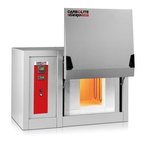
1700-1800°C Chamber Furnaces
This manual is for the guidance of operators of the above Carbolite products
and should be read before the furnace is connected to the electricity supply.
Section
1.0
2.0
3.0
4.0
5.0
6.0
7.0
8.0
9.0
Manuals for the furnace controller and overtemperature controller are
Please read the controller manuals before operating the furnace.
MF47-3.05
HTF 17 & HTF 18
Contents
supplied separately.
Page
2
3
5
8
10
15
16
18
19
1
Advertisement
Table of Contents

Related Manuals for VERDER Carbolite HTF 17


Summary of Contents for VERDER Carbolite HTF 17
-
Page 1: Table Of Contents
Installation, Operation & Maintenance Instructions 1700-1800°C Chamber Furnaces HTF 17 & HTF 18 This manual is for the guidance of operators of the above Carbolite products and should be read before the furnace is connected to the electricity supply. Contents Section Page Introduction... -
Page 2: Introduction
1.0 I NTRODUCTION HTF Range This manual applies to the 1700-1800°C furnace models HTF 17/5, HTF 17/10, HTF 18/4 and HTF 18/8, from 2003 onwards. These are bench mounted units sharing a common case size and design principles. Switches and Lights Instrument switch: when the instrument switch is operated the temperature control circuit is energised. - Page 3 2.0 I NSTALLATION Unpacking & Handling When unpacking or moving the furnace always lift it by its base. Never lift it by the door or the side panel. The furnace contains a transformer and is heavy: use two or more people to carry it. Remove any packing material from the door gear and from inside the furnace chamber.
- Page 4 Electrical Connections Connection must be made by a competent person. A qualified electrician is recommended. These models are designed only for single phase electrical supplies, or for two live phases and neutral of a 3-phase supply. The furnace must be connected only to the type and voltage of supply for which it was ordered, though some changes may be made as explained in section 2.5.
-
Page 5: Operation
3.0 O PERATION The instructions for operating the temperature controller are given in a separate manual If the furnace is fitted with a time switch, see also the supplementary manual MS03. If cascade control is fitted, see the supplementary manual MS07. Operating Cycle The furnace is fitted with an instrument switch. - Page 6 Take care that nothing hits the elements when loading of unloading. Opening the Door Take great care when loading or unloading the furnace chamber. See section 3.3. Before you remove a hot object from the furnace make sure you have a safe place to put it down. Do not open the door at high temperatures.
- Page 7 Explosive Materials The furnace must not be used to heat materials which could explode, or which could emit gases that could form explosive mixtures. 3.10 Note on Temperature Control The furnace is designed for rapid heating and cooling applications The programmer enables the furnace to heat or cool at slower rates as desired, and variable "hold"...
-
Page 8: Maintenance
4.0 M AINTENANCE Routine Maintenance Preventive rather than reactive maintenance is to be preferred. The type and frequency depends on furnace use: the following are recommended. 4.1.1 Cleaning The furnace outer surface may be cleaned with a damp cloth. Do not allow water to enter the interior of the case or chamber. - Page 9 It is advisable also to obtain element clamps and insulators (not included in kit). Individual spares are also available. When ordering spares please quote the model details as requested above. Power Adjustment (Controller) OP.Hi The furnace controller incorporates a power limit parameter which is usually inaccessible to the operator.
-
Page 10: Repairs, Replacements & Adjustments
5.0 R & A EPAIRS EPLACEMENTS DJUSTMENTS Safety Warning – Disconnection from Supply Always ensure that the furnace is disconnected from the electrical supply before repair work is carried out. Note: the Instrument switch on the front panel does not isolate the furnace from the supply. - Page 11 Connect the electrical supply with the side cover off. Take care! Set the furnace temperature to maximum. Allow the furnace to start heating up. Measure the current through the element circuit. This is done with the clip-on meter around one pair of thick cables on the left-hand side of the transformer (as seen when facing the control side of the furnace).
- Page 12 good contact is essential; poor contact can lead to sparking and destruction of the top of the element. Ensure that the elements are correctly placed: the thin part of the element, and the tapered section, should ideally be entirely within the heating chamber; the element should not touch the bottom of the chamber.
- Page 13 Element Connections – 4 Elements Terminal Block Element Braid Element Connections – 5 Elements Terminal Block Element Braid MF47-3.05...
- Page 14 Insulation Replacement Before undertaking any insulation replacement, see section 5.2. After any replacement of insulation material, run the furnace at 1500°C to burn off volatile matter. Do this is a well ventilated area. Try to ensure there is some chamber ventilated, but not too much as this could result in cracked insulation.
-
Page 15: Fault Analysis
6.0 F AULT NALYSIS A. Furnace Does Not Heat Up An ohm meter applied to A heating element has failed The HEAT light the element circuit shows is ON an open circuit The controller shows a The thermocouple has broken The HEAT light or has a wiring fault is OFF... -
Page 16: Circuit Diagram
7.0 C IRCUIT IAGRAM Single Phase 208V, 220-240V Contactor Filter GR/Y Thyr istor Heat Light Case Cooling Fans Instrument Switch Coil Element Transformer Door Thermal Switch Cutouts Fault Light Elements O/temp thermocouple Control thermocouple thermal cutouts: case temperature sensor transformer temperature sensor temperature controller OTC overtemperature controller Supply fuses (present if supply cable fitted) - Page 17 Two phase 380/220V – 415/240V Contactor Filters Thyr GR/Y istor Heat Light 94KΩ Case Cooling Fans Instrument Switch Coil Element Transformer Door Thermal Switch Cutouts Fault Light Elements O/temp thermocouple Control thermocouple thermal cutouts: case temperature sensor transformer temperature sensor temperature controller OTC overtemperature controller Supply fuses (present if supply cable fitted)
-
Page 18: Fuses & Power Control
8.0 F & P USES OWER ONTROL Fuses F1-F2: Refer to the circuit diagrams. Internal supply Fitted if a supply cable originally Ferraz fuse of the rating shown fuses fitted. Auxiliary 2 Amps type F circuit fuses 32mm x 6mm Thyristor Fuse Ferraz Protistor fuse of the rating shown... -
Page 19: Specifications
9.0 S PECIFICATIONS Carbolite reserves the right to change specifications without notice. Models Covered by this Manual MODEL Max. Max. Chamber Size (mm) Approx. Max. Temp. Power* Capacity Load Weight (°C) (kW) (kg) (kg) HTF 17/5 1700°C HTF 17/10 1700°C 10.4 HTF 18/4 1800°C... - Page 20 The products covered in this manual are only a small part of the wide range of ovens, chamber furnaces and tube furnaces manufactured by Carbolite for laboratory and industrial use. For further details of our standard or custom built products please contact us at the address below, or ask your nearest stockist.
Need help?
Do you have a question about the Carbolite HTF 17 and is the answer not in the manual?
Questions and answers