
Related Manuals for VERDER CARBOLITE GERO HZS-2G 12/425


Summary of Contents for VERDER CARBOLITE GERO HZS-2G 12/425
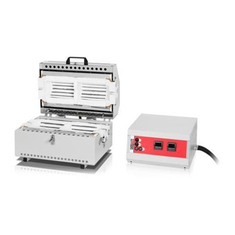
- Page 1 Installation, Operation and Maintenance Instructions 1200°C 2-Gradient Split Tube Furnace - HZS-2G Model: 425mm No Controller HZS-2G 12/425 + No Controller MEN-HZS2G12425-11_NOCTRL 02-08-2019...
-
Page 2: Table Of Contents
Contents This manual is for guidance on the use of the Carbolite Gero product specified on the front cover. This manual should be read thoroughly before unpacking and using the furnace or oven. The model details and serial number are shown on the back of this manual. - Page 3 7.0 Fault Analysis Furnace Does Not Heat Up Product Overheats 8.0 Wiring Diagrams 01890-5001 9.0 Fuses and Power Settings Fuses Power Settings User Power Setting Adjustments 10.0 Specifications 10.1 Environment...
-
Page 4: Symbols And Warnings
1.0 Symbols and Warnings 1.0 Symbols and Warnings Switches and Lights Instrument switch: when the instrument switch is operated the temperature control circuit is energised. Heat light: the adjacent light glows or flashes to indicate that power is being supplied to the elements. Heat switch: the switch disconnects power to the heating elements;... - Page 5 1.0 Symbols and Warnings Caution – Double Pole/Neutral Fusing...
-
Page 6: Installation
2.0 Installation 2.0 Installation Unpacking and Handling When unpacking or moving the product always lift it by its base or by both ends of the main body. Never lift it by its work tube or the surrounding insulation. Use two or more people to carry the product and control box. - Page 7 2.0 Installation Ensure that the product is placed in such a way that it can be quickly switched off or disconnected from the electrical supply. If the product is supplied with a work tube or any accessories fit these into position. For optimum temperature uniformity, insulating plugs should be placed in the tube ends as shown in fig.1.
- Page 8 2.0 Installation Fig 1 - Insulating Plug (standard length tube) Tube Insulating Plug Stem Fig 2 - Insulating Plug (long work tube)
-
Page 9: Electrical Connections
2.0 Installation Clamp Seal plate 'O' Ring seal D Seal sleeve Clamp seal End plate Clamp End plate Clamp seal (between Seal sleeve and Clamp D Seal sleeve Seal plate & 'O' Ring seal (underneath clamp) Tube Fig 3 'Twin Clamp' End Seal For assembly details refer to the separate work tube end seal manual. - Page 10 2.0 Installation This product requires a single-phase A.C. supply with earth (ground), which may be Live to Neutral non-reversible (polarised), Live to Neutral reversible (non-polarised), or Live to Live. Check the product rating label before connection. The supply voltage should agree with the voltage on the label and the supply capacity should be sufficient for the current on the label.
-
Page 11: Temperature Controller
3.0 Temperature Controller 3.0 Temperature Controller If this product is fitted with a temperature controller, instructions are provided separately. -
Page 12: Operation
4.0 Operation 4.0 Operation Operating Cycle This product is fitted with an instrument switch which cuts off power to the control circuit. Connect the product to the electrical supply. There is also a heater switch which can be used to disconnect power to the elements. Operate the instrument switch to activate the temperature controller. -
Page 13: Operator Safety
4.0 Operation Operator Safety The ceramic materials used in the product manufacture become electrically conductive to some extent at high temperatures. DO NOT use any conductive tools within the product without isolating it. If a metal work tube is used, it must be earthed (grounded). Switch off the heater switch whenever loading or unloading the product. -
Page 14: Power Adjustment
4.0 Operation It is recommended that a pressure relief system should be used to avoid an over pressurisation of the work tube. Please note: A product should not be heated up if any valves that have been fitted are closed to create a sealed volume. A sealed work tube should not be heated from cold due to the pressure increase caused by the trapped air or gas expanding during the heating process. -
Page 15: Maintenance
5.0 Maintenance 5.0 Maintenance General Maintenance Preventive rather than reactive maintenance is recommended. The type and frequency depends on the product use; the following are recommended. Maintenance Schedule CUSTOMER QUALIFIED PERSONNEL DANGER! ELECTRIC SHOCK. Risk of fatal injury. Only electrically qualified personnel should attempt these maintenance procedures. - Page 16 5.0 Maintenance Seals (if fitted) Check all seals and O-rings and clamps Performance Element Circuit Electrical measurement Measure the current drawn on each Power Consumption phase / circuit Check whether the cooling fans are work- Cooling Fans (if fitted)
-
Page 17: Cleaning
5.0 Maintenance 5.2.1 Cleaning Soot deposits may form inside the furnace, depending on the process. At appropriate intervals remove these by heating as indicated in the General Operation Notes. The product's outer surface may be cleaned with a damp cloth. Do not allow water to enter the interior of the case or chamber. -
Page 18: After-Sales Service
5.0 Maintenance thermocouple and temperature indicator should be made from time to time to determine whether full calibration is required. Carbolite Gero can supply these items. Depending on the controller fitted, the controller instructions may contain calibration instructions. After-Sales Service Carbolite Gero Service has a team of Service Engineers who can offer repair, calibration and preventive maintenance of furnace and oven products both at the Carbolite Gero factory and at customers’... -
Page 19: Repairs And Replacements
6.0 Repairs and Replacements 6.0 Repairs and Replacements Safety Warning - Disconnection from Power Supply Immediately switch the product off in the event of unforeseen circumstances (e.g. large amount of smoke). Allow the product to return to room temperature before inspection. Always ensure that the product is disconnected from the electrical supply before repair work is carried out. -
Page 20: Solid-State Relay Replacement
6.0 Repairs and Replacements Solid-state Relay Replacement Disconnect the product from the power supply and remove the appropriate cover as given above. 1. Make a note of the wire connections to the solid state relay, then disconnect them. 2. Remove the solid state relay from the base panel or aluminium plate. 3. -
Page 21: Element Replacement
6.0 Repairs and Replacements The fuses are located at the cable entry point. Remove the back panel or control box back panel to gain access to the fuses. Element Replacement See section 6.2 - wearing a face mask is required. Remove the three screws from each end and lift out the half-circular insulation assembly. -
Page 22: Fault Analysis
7.0 Fault Analysis 7.0 Fault Analysis Furnace Does Not Heat Up The HEAT The heating element Check also that the SSR is working light is ON has failed correctly The controller shows a The HEAT The thermocouple has broken or has very high temperature light is OFF a wiring fault... -
Page 23: Product Overheats
7.0 Fault Analysis Product Overheats Product only heats up The controller when the instrument shows a very high The controller is faulty switch is ON temperature The thermocouple may be The controller faulty or may have been shows a low removed out of the heating temperature chamber... -
Page 24: Wiring Diagrams
8.0 Wiring Diagrams 8.0 Wiring Diagrams 01890-5001... -
Page 25: Fuses And Power Settings
9.0 Fuses and Power Settings 9.0 Fuses and Power Settings Fuses F1-F3: Refer to the circuit diagrams. GEC Safeclip of the type shown Fitted if supply cable fitted. Internal (glass type F up to 16 A) Supply Fitted on board to some types 38 mm x 10 mm type F fitted on Fuses of EMC filter. -
Page 26: User Power Setting Adjustments
9.0 Fuses and Power Settings User Power Setting Adjustments Date % Power Comments Note: If a new set of elements are fitted then return the power settings to the original value. -
Page 27: Specifications
10.0 Specifications 10.0 Specifications Carbolite Gero reserves the right to change the specification without notice. Recommended Work Recommended Work Tube Heated Tube Work Tube Length for use Model Temp Power Length Weight Outer Length for use with modified (°C) (kW) (mm) (kg) Diameter... - Page 29 Notes Service Record Engineer Name Date Record of Work...
- Page 30 The products covered in this manual are only a small part of the wide range of ovens, chamber furnaces and tube furnaces manufactured by Carbolite Gero for laboratory and industrial use. For further details of our standard or custom built products please contact us at the address below, or ask your nearest stockist.
Need help?
Do you have a question about the CARBOLITE GERO HZS-2G 12/425 and is the answer not in the manual?
Questions and answers