Table of Contents
Advertisement
Quick Links
Advertisement
Table of Contents

Summary of Contents for LightViper VIS-1832
- Page 1 USER MANUAL FOR VIS-1832/VIM-1832 r061026...
- Page 2 This page intentionally left blank...
-
Page 3: Important Safety Instructions
Important Safety Instructions ATTENTION: RISQUE DE CHOC ELECTRIQUE – NE PAS OUVRIR WARNING: TO REDUCE THE RISK OF ELECTRIC SHOCK DO NOT EXPOSE THIS EQUIPMENT TO RAIN OR MOISTURE The symbols shown above are internationally accepted symbols that warn of potential hazards with electrical products. - Page 4 Warning for Your Protection 1. Read these instructions 2. Keep these instructions 3. Heed all warnings 4. Follow all instructions 5. Do not use this apparatus near water. 6. Clean only with a dry cloth. 7. Do not block any of the ventilation openings. Install in accordance with the manufacturer’s instructions.
-
Page 5: General Installation Instructions
The unit must not be heated up by external sources of heat radiation (sunlight, spot lights). Ambient Temperature Units and systems by LightViper are generally designed for an ambient temperature range (i.e. temperature of the incoming air) of +5...+40 °C. When rack mounting the units, the following facts must be considered: The admissible ambient temperature range for operation of the semiconductor components is 0 °C to +70 °C (commercial temperature range for operation). - Page 6 Earthing and Power Supply Earthing of units with mains supply (class I equipment) is performed via the protective earth (PE) conductor integrated in the mains cable. Units with battery operation (< 60 V, class III equipment) must be earthed separately. Earthing the unit is one of the measures for protection against electrical shock hazard (dangerous body currents).
-
Page 7: Limited Lifetime Warranty
Registration Be sure to register your LightViper product, either by filling in the enclosed Registration Card or by completing the on-line registration form at our Web site: http://lightviper.com/register.aspx If you do so, FiberPlex can contact you with any update information. As enhancements and upgrades are developed, you will be contacted at the registration address. -
Page 8: Declarations Of Conformity
If you have any questions with regard to the above, please contact FiberPlex. In the event your LightViper equipment needs to be upgraded or repaired, it is necessary to contact FiberPlex prior to shipping, and a Return Materials Authorization (RMA) number will be assigned. - Page 9 The Light Viper You have purchased the LightViper 1832 system, a 32 x 8 Fiber Optic Transport System (FTS) that has the function, look and feel of a traditional copper snake; however instead of a heavy multi-conductor cable the Light Viper snake features a lightweight, flexible fiber built to “ruggedized”...
-
Page 10: Standard Components
In its standard configuration, the Light Viper 1832 is made up of the following primary components. • The Stage Box (VIS-1832) — This is the box placed close to all the inputs. It can be placed on the stage or rack mounted with the optional VER-1832 rack ears. -
Page 11: Getting Started
Connect the inputs and returns to the stage box. (Be sure to select the appropriate Gain and Phantom Power settings) Connect the fan out cables to the console (send & return on VIS-1832, send only on VIS-1032) Turn on phantom power as necessary. - Page 12 26 dB, and 46 dB. All inputs accept balanced or unbalanced signals, eliminating the need for adapters and DI boxes. The Clip LED will flash at 3 dB below peak clipping. (+16 dBu). The XLR inputs of the VIS-1832 have an input impedance of 1.8KΩ while the TRS has an input impedance of 1.8KΩ.
- Page 13 Stage Box and any other send units that are connected via the optical Power Connector/Fuse - Power to the Mixer Box is provided with splits all sync to the clock provided by the master. The LightViper 1832 system the supplied 3-Prong IEC Power Cord. The internal power supply can accept runs natively at 24 bit/ 96k, but can also run at 24 bit / 48k with a 48k clock any voltage from 90-260 at either 50 or 60Hz.
- Page 14 Cables Fiber Cable - (TFC-0000-04) The Fiber Optic ‘cable’ is the centerpiece of the Light Viper system. Weighing 8.4 lbs. (12.6kg) for (300) feet, the cable carries all (40) signals between the stage box and the Mixer Box. Additional cables connect the Stage Box to up to two more send boxes (splits).
- Page 15 Using the Light Viper 1832 —Live Sound This image illustrates how the Light Viper might be used in a live sound situation. The system accommodates all the signal needs of the main PA, monitor mix and truck based recording.
- Page 16 Using the Light Viper 1832 —Fixed Installation This image illustrates how the Light Viper might be used in a fixed install situation. The thin, lightweight cable can be run without conduit through walls and over drop ceilings dramatically reducing install costs.
- Page 17 Using the Light Viper 1832 —Remote Recording This image illustrates how the Light Viper might be used in a remote recording situation. The system allows for cable runs you could never consider with analog copper wires.
- Page 18 Sync LED LED (green) indicates optical link OK, LED (red) indicates problem with optical link, LED (off) indicates no power. AC Power Universal 90-250 VAC, 50/60 Hz, IEC connector with fuse (VIM-1832), Neutrik PowerCon with fuse (VIS-1832) Max Current Rating VIS-1832 0.463 mA @ 90V...
- Page 19 Appendix ANALOG – DB25 Cable Pin Outs Ch. 8 + Ch. 8 - Ch. 8 G Ch. 7 + Ch. 7 - Ch. 7 G Ch. 6 + Ch. 6 - Ch. 6 G Ch. 5 + Ch. 5 - Ch.
- Page 20 VER-1832 Rack Ears Available rack mount kits for the VIS-1832 have 1, 2 or 3 panel mount TAC-4 connectors mounted respectively and allow connection between tactical grade fiber to the ST connectors on the VIS units. The illustration below is in the T-1 configuration.
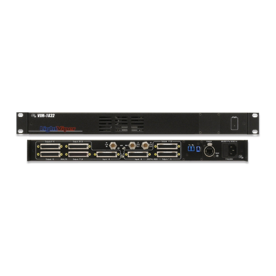
- Page 21 VIM-1832 Dimensions VIS-1832 Dimensions...
Need help?
Do you have a question about the VIS-1832 and is the answer not in the manual?
Questions and answers