Table of Contents
Advertisement
INSTALLATION, OPERATION,
AND MAINTENANCE MANUAL
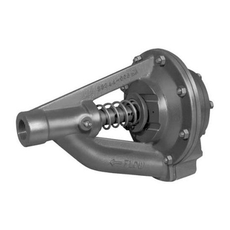
AUTOMATIC AIR RELEASE VALVES
GRP33-07
GRP33-07A
GRP33-07D
GRP33-07E
GRP33-07H
GRP33-07J
GRP33-07M
GRP33-07N
GRP33-07S
GRP33-07T
WITH PARTS LIST
MODELS
GRP33-07B
GRP33-07F
GRP33-07K
GRP33-07P
GORMAN‐RUPP PUMPS
www.grpumps.com
e
1986 Gorman‐Rupp Pumps
GL‐00073‐03
July 15, 1986
Rev. T 06-30-20
GRP33-07C
GRP33-07G
GRP33-07L
GRP33-07R
Printed in U.S.A.
Advertisement
Table of Contents

Related Manuals for GORMAN-RUPP PUMPS GRP33-07


Summary of Contents for GORMAN-RUPP PUMPS GRP33-07
- Page 1 GL‐00073‐03 July 15, 1986 Rev. T 06-30-20 INSTALLATION, OPERATION, AND MAINTENANCE MANUAL WITH PARTS LIST AUTOMATIC AIR RELEASE VALVES MODELS GRP33-07 GRP33-07A GRP33-07B GRP33-07C GRP33-07D GRP33-07E GRP33-07F GRP33-07G GRP33-07H GRP33-07J GRP33-07K GRP33-07L GRP33-07M GRP33-07N GRP33-07P GRP33-07R GRP33-07S GRP33-07T GORMAN‐RUPP PUMPS www.grpumps.com...
- Page 2 Register your new Gorman‐Rupp pump online at www.grpumps.com/register. Valid serial number and e‐mail address required. RECORD YOUR PUMP MODEL AND SERIAL NUMBER Please record your pump model and serial number in the spaces provided below. Your Gorman‐Rupp distributor needs this information when you require parts or service. Pump Model: Serial Number:...
-
Page 3: Table Of Contents
... . . PAGE E - 1 PARTS LISTS: GRP33-07, 07A, 07B, 07J, 07K, 07M And 07P Air Release Valves ... PAGE E - 3 GRP33-07C, 07D, 07E And 07F Air Release Valves . -
Page 4: Introduction
G‐R OM-00073 INTRODUCTION Thank You for purchasing a Gorman‐Rupp Auto tion, to those which could damage equipment, and matic Air Release Valve. Read this manual careful to those which could be dangerous to personnel: ly to learn how to safely install and operate your pump. -
Page 5: Safety - Section A
G‐R GL-00073 SAFETY - SECTION A This information applies to Gorman‐ 4. Check the temperature before Rupp Automatic Air Release Valves. Re opening any covers, plates, or fer to the manual accompanying the plugs. pump and power source before at 5. -
Page 6: Installation - Section B
G‐R GL-00073 INSTALLATION - SECTION B Review all SAFETY information in Section A. b. Check for and tighten loose attaching hard ware at mating surfaces. Since pump installations are seldom identical, this c. Check the plunger rod for free movement by section offers only general recommendations and compressing the spring with an appropriate practices required to inspect and install the Auto... - Page 7 GL-00073 G‐R The valve inlet line must be installed between the Release Valve to be removed for service while the pump discharge port and the non‐pressurized side pump remains in operation. of the discharge check valve. The valve inlet is at the large end of the valve body, and is provided with standard 1‐inch NPT pipe threads.
-
Page 8: Operation - Section C
GL-00073 G‐R OPERATION - SECTION C THEORY OF OPERATION presses the spring and closes the valve (Figure C-2). The valve will remain closed, reducing the bypass of liquid to 1 to 5 gallons (3,8 to 19 liters) per Review all SAFETY information in Section A. minute, until the pump loses its prime or stops. -
Page 9: Adjustment
GL-00073 G‐R With the pin located in the hole nearest the dia AIR RELEASE VALVE CONSTRUCTION phragm, the valve will close at the minimum dis AND APPLICATION DATA charge head (pressure) for that particular spring. With the pin located in the hole farthest from the di aphragm, the valve will close at the maximum dis... -
Page 10: Troubleshooting - Section D
G‐R GL-00073 TROUBLESHOOTING - SECTION D Review all SAFETY information in Section A. Before attempting to service the Air Re lease Valve: 1. Familiarize yourself with this manual. 2. Lock out or disconnect the power source to ensure that the pump will remain inoperative. - Page 11 GL-00073 G‐R TROUBLE POSSIBLE CAUSE PROBABLE REMEDY VALVE FAILS TO Plunger rod needs lubrication. Lubricate rod as indicated in OPEN LUBRICATION, Section E. Bleed line or diaphragm cavity Clean bleed line (particularly at 90_ clogged. elbows). Remove inspection cover and clean diaphragm cavity. Valve hydraulically locked.
- Page 12 G‐R GL-00073 equipped) between regularly scheduled inspec PREVENTIVE MAINTENANCE tions can indicate problems that can be corrected Since pump applications are seldom identical, and before system damage or catastrophic failure oc pump wear is directly affected by such things as curs.
-
Page 13: Maintenance And Repair - Section E
4‐17 FT. 18‐49 FT. 50 FT. + 4‐17 FT. 18‐49 FT. 50 FT. + NUMBER DISCH. HEAD DISCH. HEAD DISCH. HEAD DISCH. HEAD DISCH. HEAD DISCH. HEAD GRP33-07 GRP33-07A GRP33-07B GRP33-07C GRP33-07D GRP33-07E GRP33-07F GRP33-07G GRP33-07H GRP33-07J GRP33-07K GRP33-07L GRP33-07M... - Page 14 GL-00073 G‐R ILLUSTRATION PARTS PAGE Figure 1. GRP33-07, GRP33-07A, GRP33-07B GRP33-07J, GRP33-07K, GRP33-07M And GRP33-07P Air Release Valves PAGE E - 2 MAINTENANCE & REPAIR...
-
Page 15: Parts Lists
GL-00073 G‐R PARTS LIST GRP33-07, GRP33-07A And GRP33-07B Air Release Valves This Parts List Represents Bill of Material Issue 3 For These Valves GRP33-07J, GRP33-07K, GRP33-07M And GRP33-07P Air Release Valves This Parts List Represents Bill of Material Issue 1 For These Valves... - Page 16 GL-00073 G‐R ILLUSTRATION Figure 2. GRP33-07C, GRP33-07D, GRP33-07E And GRP33-07F Air Release Valves PAGE E - 4 MAINTENANCE & REPAIR...
- Page 17 GL-00073 G‐R PARTS LIST GRP33-07C, GRP33-07D, GRP33-07E And GRP33-07F Air Release Valves This Parts List Represents Bill of Material Issue 2 For These Valves ITEM PART PART NAME NUMBER INSPECTION COVER 38346-610 17070 OUTER DIAPHRAGM WASHER 31711-029 NYLON LOCK NUT BC08 17040 INSPECTION COVER O‐RING 25152-152...
- Page 18 GL-00073 G‐R ILLUSTRATION Figure 3. GRP33-07G, GRP33-07H, GRP33-07L, GRP33-07N, GRP33-07R, GRP33-07S AND GRP33-07T Air Release Valves PAGE E - 6 MAINTENANCE & REPAIR...
- Page 19 GL-00073 G‐R PARTS LIST GRP33-07G, GRP33-07H, GRP33-07L, GRP33-07N, GRP33-07R, GRP33-07S And GRP33-07T Air Release Valves This Parts List Represents Bill of Material Issue 1 For These Valves ITEM PART PART NAME NUMBER INSPECTION COVER 38346-610 17070 OUTER DIAPHRAGM WASHER 31711-029 NYLON LOCK NUT BC08 17040 GRP33-07G, 07H, 07R INSPECT CVR O‐RING 25158-658...
-
Page 20: Air Release Valve Disassembly And Reassembly
GL-00073 G‐R AIR RELEASE VALVE DISASSEMBLY 4. Check the temperature before opening any covers, plates, or AND REASSEMBLY plugs. 5. Close the suction and discharge Review all SAFETY information in Section A. valves. 6. Vent the pump slowly and cau tiously. -
Page 21: Air Release Valve Reassembly
G‐R GL-00073 is available from the factory. To use the tool, turn the servicing the pump or Automatic Air Re capscrews until the ends are just flush with the lease Valve. compressor plate. Lightly compress the spring far enough to allow the compressor plate to be posi tioned over the spring retaining washer so the ends of both capscrews seat against the valve body. - Page 22 GL-00073 G‐R Inspect the parts for wear or damage and replace spring is great enough to cause serious as necessary. injury to personnel if the spring should slip and be ejected. Wear safety glasses, use a suitable spring compres sion tool, ensure that personnel are clear of the work area and use extreme Most cleaning solvents are toxic and caution when installing or removing...
-
Page 23: Lubrication
G‐R GL-00073 dicated in the seal lubrication schedule shown in lost prime to continue to operate with the Preventive Maintenance Schedule, page D-3. out reaching prime, causing dangerous overheating and possible explosive If the valve sticks or operates erratically during nor rupture of the pump casing. - Page 24 For Warranty Information, Please Visit www.grpumps.com/warranty or call: U.S.: 419-755-1280 Canada: 519-631-2870 International: +1-419-755-1352 GORMAN‐RUPP PUMPS...
Need help?
Do you have a question about the GRP33-07 and is the answer not in the manual?
Questions and answers