Table of Contents
Advertisement
Quick Links
PILOT'S OPERATING
HANDBOOK
VELIS Electro
Document No.: POH-128-00-40-001
REVISION B00
Date of Issue: June 10
Signature:
Registration:
Serial No.:
All rights reserved. Reproduction or disclosure to third parties of this document or any
part thereof is not permitted, except with the prior and express written permission of
Pipistrel Group's R&D division, Pipistrel Vertical Solutions d.o.o., which is authorized to
publish technical documentation for Pipistrel Group's subsidiaries.
, 2020
th
Digitally signed by
Vid Plevnik
Reason: HOA
Location: Ajdovscina, Slovenia, EU
Date: 2020/06/10 15:21 +02'00'
____________________________
____________________________
Advertisement
Chapters
Table of Contents

Related Manuals for Pipistrel VELIS Electro


Summary of Contents for Pipistrel VELIS Electro
- Page 1 All rights reserved. Reproduction or disclosure to third parties of this document or any part thereof is not permitted, except with the prior and express written permission of Pipistrel Group’s R&D division, Pipistrel Vertical Solutions d.o.o., which is authorized to publish technical documentation for Pipistrel Group’s subsidiaries.
- Page 2 Aircraft type: Virus SW 121 Model: Virus SW 128 T.C. no.: EASA.A.573 Type certificate holder: PIPISTREL VERTICAL SOLUTIONS d.o.o. Vipavska cesta 2 SI-5270 Ajdovščina Slovenia Tel: + 386 5 36 63 873 Fax: + 386 5 36 61 263 Email: info@pipistrel.si This handbook includes all of the material required to be provided to the pilot by CS-LSA regulations.
- Page 3 VELIS Electro Pilot's Operating Handbook Table of contents SECTION CONTENTS FOREWORD GENERAL LIMITATIONS EMERGENCY PROCEDURES NORMAL PROCEDURES PERFORMANCE DATA WEIGHT AND BALANCE AIRPLANE DESCRIPTION HANDLING AND SERVICING APPENDIX POH 128 00 40 001 PAGE PAGE REV. 0...
- Page 4 The same system applies when the header, figure or any other element inside this POH is revised. A list of revisions is located at the beginning of the log of effective pages. Pipistrel is not responsible for technical changes/updates to OEM manuals supplied with the aircraft (e.g.
- Page 5 VELIS Electro Pilot's Operating Handbook Index of document revisions Doc. Reason for A ected pages Authority Rev. revision EASA Initial 10.06.2020 POH 128 00 40 001 PAGE PAGE REV. 0...
- Page 6 VELIS Electro Pilot's Operating Handbook List of e ective pages PAGE PAGE PAGE PAGE PAGE PAGE PAGE PAGE NUMBER REV. NUMBER REV. NUMBER REV. NUMBER REV. Cover 2 - 1 3 - 1 3 - 35 2 - 2 3 - 2...
- Page 7 VELIS Electro Pilot's Operating Handbook PAGE PAGE PAGE PAGE PAGE PAGE PAGE PAGE NUMBER REV. NUMBER REV. NUMBER REV. NUMBER REV. 4 - 1 5 - 1 7 - 1 3 - 69 4 - 2 7 - 2 5 - 2...
- Page 8 VELIS Electro Pilot's Operating Handbook PAGE PAGE PAGE PAGE PAGE PAGE PAGE PAGE NUMBER REV. NUMBER REV. NUMBER REV. NUMBER REV. 7 - 34 8 - 1 9-A0-1 7 - 35 8 - 2 9-A0-2 7 - 36 8 - 3...
- Page 9 SECTION...
-
Page 10: Table Of Contents
VELIS Electro Pilot's Operating Handbook SECTION 1 – GENERAL TABLE OF CONTENTS PART SUBJECT PAGE NUMBER INTRODUCTION DESCRIPTION CERTIFICATION BASIS THREE VIEW DRAWINGS DIMENSIONS AND WEIGHTS SYSTEMS Engine Propeller Battery System Landing Gear SYMBOLS, ABBREVIATIONS and TERMINOLOGY CONVERSION TABLE 1-11... -
Page 11: Introduction
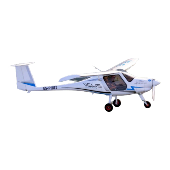
1.2. DESCRIPTION The VELIS Electro is a two-seat aircraft of composite construction. The air- craft is arranged as a high wing mono-plane with cantilevered wings and a conventional empennage with a T-tail. It is equipped with a Pipistrel electric engine E-811-268MVLC and a fixed pitch propeller Pipistrel P-812-164-F3A. -
Page 12: Three View Drawings
VELIS Electro SECTION 1 Pilot's Operating Handbook GENERAL 1.4. THREE VIEW DRAWING VELIS Electro 3-view drawing POH 128 00 40 001 PAGE PAGE REV. 0... -
Page 13: Dimensions And Weights
ENGINE The aircraft's Pipistrel E-811-268MVLC engine consists of an electric motor, the Pipistrel 268 MVLC VHML, and a dedicated H300C controller, which pro- vides a maximum rated take o power of 65 kW. The motor is a liquid cooled, axial flux synchronous permanent magnet elec- tric motor. -
Page 14: Propeller
Propulsion system terminology 1.6.2. PROPELLER VELIS Electro is equipped with a 3-blade fixed pitch, Pipistrel-designed P-812-164-F3A propeller. It has a diameter 1640 mm. Its blades are made from carbon fiber composite material and stainless steel. The blade root and propeller hub are machined aluminum parts. -
Page 15: Symbols, Abbreviations And Terminology
VELIS Electro SECTION 1 Pilot's Operating Handbook GENERAL 1.7. SYMBOLS, ABBREVIATIONS AND TERMINOLOGY 1.7.1. GENERAL AIRSPEED TERMINOLOGY AND SYMBOLS KCAS Knots Calibrated Airspeed is the indicated airspeed corrected for posi- tion and instrument error expressed in knots. Calibrated airspeed (CAS) is equal to true airspeed in standard atmosphere at sea level. - Page 16 VELIS Electro SECTION 1 Pilot's Operating Handbook GENERAL 1.7.2. METEOROLOGICAL TERMINOLOGY Instrument Meteorological Conditions are meteorological conditions ex- pressed in terms of visibility, distance from cloud, and ceiling less than the minimal for visual flight defined in FAR 91.155. International Standard Atmosphere (standard day) is an atmosphere...
- Page 17 VELIS Electro SECTION 1 Pilot's Operating Handbook GENERAL 1.7.3. PROPULSION SYSTEM TERMINOLOGY Battery Management System ENGINE In this POH is defined as the system composed by electric motor and power controller. Horsepower is the power developed by the motor. INTERLOCK A system that detects power cable connection to the battery box.
- Page 18 Minimum List of Equipment is the list of instruments, systems and equip- ment that must be on board and functional for a kind of operation. Take O Mass is the aircraft mass at take o . On VELIS Electro this value does not change during the entire flight.
-
Page 19: Conversion Table
VELIS Electro SECTION 1 Pilot's Operating Handbook GENERAL 1.7.6. ADDITIONAL ABBREVIATIONS Artificial Horizon AHRS Attitude and Heading Reference System Angle Of Attack BATT Battery/Batteries Communication - Radio Electrical Aircraft Emergency Locator Transmitter High Voltage Instrumental Flight Rules NVFR Night-Visual Flight Rules... -
Page 20: List Of Applicable Documents
VELIS Electro SECTION 1 Pilot's Operating Handbook GENERAL 1.9 LIST OF APPLICABLE DOCUMENTS Reference Document WBR-128-08-10-XXX* Weight and Balance Report ELT_345_Manual_Y1-03-0282J EIM-811-00-60-7202 Engine Operator`s Manual PIM-812-61-00-001 Propeller Instruction Manual AMM-128-00-60-001 Aircraft maintenance manual Horis - Installation and User Manual (by Kanardia d.o.o.) SB-128-00-80-001 Flight_Data_Logging SPOH-128-00-40-001 Leaflet ground risks... - Page 21 SECTION...
- Page 22 VELIS Electro Pilot's Operating Handbook SECTION 2 – LIMITATIONS TABLE OF CONTENTS PART SUBJECT PAGE NUMBER INTRODUCTION AIRSPEED LIMITATION AIRSPEED INDICATOR MARKINGS ENGINE AND PROPELLER LIMITATIONS ENGINE INSTRUMENT MARKINGS WEIGHT AND CENTER OF GRAVITY LIMITS OCCUPANCY COOLANT FLIGHT LOAD FACTOR LIMITS 2.10...
-
Page 23: Introduction
VELIS Electro SECTION 2 Pilot's Operating Handbook LIMITATIONS 2.1 INTRODUCTION This section provides operating limitations, instrument markings and basic placards necessary for the safe operation of the airplane and its standard systems and equipment. 2.2 AIRSPEED LIMITATIONS All speeds in the table below are KIAS. -
Page 24: Airspeed Indicator Markings
VELIS Electro SECTION 2 Pilot's Operating Handbook LIMITATIONS 2.3 AIRSPEED INDICATOR MARKINGS All speeds in the table below are KIAS. MARKING VALUE REMARKS Flap Operating Range. Lower limit is the most White adverse stall speed in the landing configuration. 46 - 81 Upper limit is the maximum speed permissible with flaps extended at 1... -
Page 25: Engine Instrument Markings
VELIS Electro SECTION 2 Pilot's Operating Handbook LIMITATIONS 2.5 ENGINE INSTRUMENT MARKINGS EPSI570C RED LINE GREEN ARC YELLOW ARC RED LINE EPSI570C MINIMUM NORMAL CAUTION MAXIMUM Tachometer 0 / 2299 2300 / 2499 2500 (RPM) Motor temp. (°C) (-20) / 99 100 / 109 Power controller temp. -
Page 26: Coolant
VELIS Electro SECTION 2 Pilot's Operating Handbook LIMITATIONS COOLANT Motor, power electronics and batteries are liquid cooled (distilled water/glycol). 50% water + 50% glycol Approved coolant automotive grade G12+ Marked on expansion tanks, Min/max coolant quantity visible through check windows 0.9 L for engine system... -
Page 27: Altitude Limits
VELIS Electro SECTION 2 Pilot's Operating Handbook LIMITATIONS 2.11 ALTITUDE LIMITS Maximum operating altitude 12,000 ft MSL 2.12 TEMPERATURE LIMITS Do not fly when the temperature of the aircraft’s surface is at risk of ex- ceeding 55 °C. Aircraft can be operated between -20 °C < OAT < +35 °C Batteries should be stored between 0 °C <... - Page 28 VELIS Electro SECTION 2 Pilot's Operating Handbook LIMITATIONS 2.14.1 MINIMUM LIST OF EQUIPMENT MLE REQUIRED FOR KIND OF SYSTEM, OPERATION (item Qty) INSTRUMENT, EQUIPMENT VHF COM / (NAV) Transponder — Low Voltage Battery (aux battery) Ammeter / Indication Emergency Locator Trans.
-
Page 29: Operational Restrictions
VELIS Electro SECTION 2 Pilot's Operating Handbook LIMITATIONS 2.15 OPERATIONAL RESTRICTIONS Flight under Instrument Flight Rules (IFR) is not permitted. NVFR Flight is not permitted. Minimum SOC at take o = 50%. Standard mission planning must consider 30% SOC as minimum value at landing. -
Page 30: Placards
VELIS Electro ROCKET GAS SECTION 2 Pilot's Operating Handbook LIMITATIONS EXHAUST 2.16 PLACARDS ROCKET GAS MAX EXTENSION SPEED FLAPS 2.16.1 PLACARDS EXTERNAL OPERATING SPEEDS EXHAUST KIAS KIAS KIAS KIAS KIAS INFLATE TO INFLATE TO Next to nose wheel KTAS 2.8 bar 1.8 bar... -
Page 31: Placards Engine And Batt Compartments
VELIS Electro SECTION 2 Pilot's Operating Handbook LIMITATIONS Next to battery cooling inlet/outlet on the fuselage KEEP CLEAR! KEEP CLEAR! BATTERY COOLING INLET BATTERY COOLING OUTLET 1111590 1111502 Next to engine and battery cooling system coolant overflow hoses ENG. COOLANT BATT. -
Page 32: Placards Instrument Panel
1111503 MOGAS AVGAS 100LL OPEN CLOSED min. 95 RON VELIS Electro (AKI 91) SECTION 2 1111551 max. 10% ethanol content Pilot's Operating Handbook WARNING! LIMITATIONS When using AVGAS 100LL, change oil and oil filter every 50 hrs FUEL QTY 50 LITRES PULL FOR PARACHUTE (13.2 USgal) - Page 33 VELIS Electro SECTION 2 Pilot's Operating Handbook LIMITATIONS On the left and right side of the instrument panel SOFTWARE UPGRADE PORT DATA LOGGER PORT PORT 2.16.4 PLACARDS CENTER CONSOLE ROCKET GAS EXHAUST Next to flap lever INFLATE TO INFLATE TO 2.8 bar...
-
Page 34: Placards Cabin
EXHAUS OPEN LIFT FL180 KNOB VELIS Electro SECTION 2 FULL DANGER Pilot's Operating Handbook INFLATE TO INFLAT WEAK LINK MAX 300 kg 2.8 bar 1.8 b LIMITATIONS 1111552 TOW HOOK 2.16.5 PLACARDS CABIN DANGER 1111821 MTOW 1111534 CREW WT 1111717... -
Page 35: Placards External High Voltage Hazard
VELIS Electro SECTION 2 Pilot's Operating Handbook LIMITATIONS 2.16.6 PLACARDS EXTERNAL HIGH VOLTAGE HAZARD On battery compartment access panels (3x) On the aircraft belly (3x) APPROVED POH 128 00 40 001 PAGE 2-15 PAGE REV. 0... - Page 36 This page is intentionally left blank.
- Page 37 SECTION...
- Page 38 VELIS Electro Pilot's Operating Handbook SECTION 3 – EMERGENCY PROCEDURES TABLE OF CONTENTS PART SUBJECT PAGE NUMBER INTRODUCTION WARNING / CAUTION INDICATION SYSTEM EPSI570C Warning and Caution Messages AIRSPEEDS FOR EMERGENCY OPERATIONS 3-11 GROUND EMERGENCIES 3-11 Engine Fire on Ground...
- Page 39 VELIS Electro SECTION 3 Pilot's Operating Handbook EMERGENCY PROCEDURES PART SUBJECT PAGE NUMBER No Go-around Available Battery SOC Adjusted Battery Cell Low Voltage Battery Coolant Pump Failure Engine Communication Failure Engine Coolant Pump Failure Electrical System Insulation Failure DC/DC Converter Failures (in Flight)
- Page 40 This page is intentionally left blank.
-
Page 41: Introduction
VELIS Electro SECTION 3 Pilot's Operating Handbook EMERGENCY PROCEDURES INTRODUCTION This section provides procedures for handling emergencies and critical flight situations. Although emergencies caused by airplane, systems, or engine malfunctions are extremely rare, the guidelines described in this section should be considered and applied as necessary should an emer- gency arise. -
Page 42: Warning/Caution Indication System
VELIS Electro SECTION 3 Pilot's Operating Handbook EMERGENCY PROCEDURES Land immediately Continuation of the flight may be more hazardous than ditching or landing in terrain normally considered unsuitable. Land as soon as possible Find the nearest suitable area, such as an open field, at which a safe ap- proach and landing is assured, and land without delay. - Page 43 VELIS Electro SECTION 3 Pilot's Operating Handbook EMERGENCY PROCEDURES The 58 °C threshold coincides also with the temperature at which automatic disconnection of the battery is triggered by the digital system. This is accom- panied by a warning message on EPSI570C and annunciator.
-
Page 44: Epsi570C Warning And Caution Messages
VELIS Electro SECTION 3 Pilot's Operating Handbook EMERGENCY PROCEDURES 3.2.1 EPSI570C WARNING AND CAUTION MESSAGES The following table presents the possible warning and caution messages that appear on the EPSI570C display. WARNING: Do not take o if any warning or caution appears on the EPSI570C display, annunciator panel or battery overtemperature warning lights. - Page 45 VELIS Electro SECTION 3 Pilot's Operating Handbook EMERGENCY PROCEDURES 3.4.7 The system is unable to communicate BATTERY F/R 3.4.9 with the battery. 3.5.5 NOT PRESENT (via CAN-bus communication system) 3.5.8 This caution appears when the power controller is ON and when motor RPM 3.4.7...
- Page 46 VELIS Electro SECTION 3 Pilot's Operating Handbook EMERGENCY PROCEDURES ENGINE CAUTIONS Caution Message Description Section Power controller temperature motor temperature in caution range. If ENGINE HIGH 3.4.9 temperatures keep increasing expect TEMPERATURE 3.5.9 "Engine Overtemperature" warning message. ENGINE Power setting can't be changed and 3.4.10...
-
Page 47: Airspeeds For Emergency Operations
VELIS Electro SECTION 3 Pilot's Operating Handbook EMERGENCY PROCEDURES 3.3 AIRSPEEDS FOR EMERGENCY OPERATIONS Maneuvering Speed: 100 KIAS Best Glide Speed (flaps 0): 70 KIAS Emergency Landing (Engine-out) - Final approach speeds: Flaps 0 63 KIAS Flaps +1 60 KIAS... -
Page 48: Emergency Ground Egress
VELIS Electro SECTION 3 Pilot's Operating Handbook EMERGENCY PROCEDURES Come to a complete standstill MASTER switch BATT EN switch BATT REAR & BATT FRONT circuit breakers DISENGAGE Emergency ground egress procedure (3.4.4) PERFORM WARNING: Be aware that lithium battery fires are extremely dangerous because they are self-sustaining! They are a result of a chemical reactions and are impossible to extinguish. -
Page 49: Battery Failure At System Start-Up
VELIS Electro SECTION 3 Pilot's Operating Handbook EMERGENCY PROCEDURES While exiting the airplane, make sure the evacuation path is clear of other aircraft, spinning propellers and/or other hazards. 3.4.5 BATTERY FAILURE AT SYSTEM START UP The system performs a self test on electrical components during the start-up phase. -
Page 50: Battery Coolant Fan Failure
VELIS Electro SECTION 3 Pilot's Operating Handbook EMERGENCY PROCEDURES 3.4.6 BATTERY COOLANT FAN FAILURE The battery coolant fan is used during the recharging phase. If the battery coolant fan fails, charging power is derated to 0 kW (see also Section 8 for... -
Page 51: Dc/Dc Converter Failures
VELIS Electro SECTION 3 Pilot's Operating Handbook EMERGENCY PROCEDURES pens at the power line interface of the battery, the following message ap- pears on the EPSI570C as soon as RPM reaches 300 RPM, to avoid take o with a single battery delivering power. -
Page 52: Propulsion System Component Failures
VELIS Electro SECTION 3 Pilot's Operating Handbook EMERGENCY PROCEDURES 3.4.9 PROPULSION SYSTEM COMPONENT FAILURES CAUTION: If any warning or caution messages related to propulsion system components appear while on the ground (engine or battery high tempera- ture, engine overtemperature, battery overcurrent, coolant pumps, battery disconnection etc), do not take o . - Page 53 VELIS Electro SECTION 3 Pilot's Operating Handbook EMERGENCY PROCEDURES EPSI570C message Annunciator POWER LEVER COMMUNICA- TION FAILURE (amber) EPSI570C message Annunciator ENGINE COMMUNICATION FAILURE (amber) - If the take o run is not initiated yet: PWR CTRL circuit breaker DISENGAGE...
-
Page 54: In-Flight Emergencies
VELIS Electro SECTION 3 Pilot's Operating Handbook EMERGENCY PROCEDURES IN FLIGHT EMERGENCIES 3.5.1 COMPLETE POWER LOSS AFTER TAKE OFF If complete power loss occurs immediately after becoming airborne and a runway landing is possible, abort with a runway landing. If, however, altitude attained precludes a runway stop, but is not su cient to restart the motor, lower the nose to maintain airspeed and establish a glide attitude. -
Page 55: Complete Power Loss In Flight
VELIS Electro SECTION 3 Pilot's Operating Handbook EMERGENCY PROCEDURES 3.5.2 COMPLETE IN FLIGHT POWER LOSS If the power is lost at altitude, pitch down as necessary to establish best glide speed. While gliding toward a suitable landing area, attempt to identify the cause of the failure and correct it. -
Page 56: Motor Restart In Flight
VELIS Electro SECTION 3 Pilot's Operating Handbook EMERGENCY PROCEDURES 3.5.3 MOTOR RESTART IN FLIGHT NOTE: The minimum height, at which a motor restart attempt can be made safely, is 1000 ft AAL. Attempt to restart the motor in flight following these steps:... - Page 57 VELIS Electro SECTION 3 Pilot's Operating Handbook EMERGENCY PROCEDURES Partial power loss at take off Partial power loss is most critical during take o . The time available to assess the situation is limited and the pilot has to react quickly.
-
Page 58: Battery Disconnected
VELIS Electro SECTION 3 Pilot's Operating Handbook EMERGENCY PROCEDURES 3.5.5 BATTERY DISCONNECTED Single Battery Disconnection Battery disconnection can be either manual, by disengaging the battery cir- cuit breaker, or automatic, triggered by the system. In case of automatic battery disconnection, the EPSI570C will display a warning message identifying which battery has been disconnected (F=Front or R=Rear) and the reason for disconnection. - Page 59 VELIS Electro SECTION 3 Pilot's Operating Handbook EMERGENCY PROCEDURES Subsequent, and consequently, to battery circuit breaker disengagement (this action will cause loss of communication with the battery and parameters such as battery temperature and voltage will no longer be available - see...
-
Page 60: Battery High Temperature
VELIS Electro SECTION 3 Pilot's Operating Handbook EMERGENCY PROCEDURES 3.5.6 BATTERY HIGH TEMPERATURE If battery temperature enters the caution range (between 51°C and 57 °C), EPSI570C and annunciator will display the following caution message: EPSI570C message Annunciator BATTERY F/R HIGH TEMPERATURE (amber) -
Page 61: Battery Overtemperature
VELIS Electro SECTION 3 Pilot's Operating Handbook EMERGENCY PROCEDURES 3.5.7 BATTERY OVERTEMPERATURE If battery temperatures continue to rise, entering the warning range (≥ 58 °C), the battery is automatically disconnected by the system. Expect the following message to appear: EPSI570C message... - Page 62 VELIS Electro SECTION 3 Pilot's Operating Handbook EMERGENCY PROCEDURES Land IMMEDIATELY Airplane EVACUATE - If warning is signalled by only one of the alert systems (battery overtem- perature warning lights only OR EPSI warning only): AS SOON AS Land POSSIBLE * NOTE: After battery circuit breaker disengagement, communication with the battery is lost.
-
Page 63: Battery Not Present
VELIS Electro SECTION 3 Pilot's Operating Handbook EMERGENCY PROCEDURES 3.5.8 BATTERY NOT PRESENT Single battery loss of communication EPSI570C message Annunciator BATTERY F/R NOT PRESENT (amber) Single battery disconnec- PERFORM tion procedure (3.5.5) Communication loss with one battery is indicated by a single caution mes- sage. -
Page 64: Engine High Temperature
VELIS Electro SECTION 3 Pilot's Operating Handbook EMERGENCY PROCEDURES 3.5.9 ENGINE HIGH TEMPERATURE If engine (motor or power controller) temperature enters the caution range (65 °C - 69 °C for power controller or 100 °C - 109 °C for the motor) the following... -
Page 65: Engine Overtemperature
VELIS Electro SECTION 3 Pilot's Operating Handbook EMERGENCY PROCEDURES 3.5.10 ENGINE OVERTEMPERATURE If engine temperature continues to increase and enters the warning range (70 °C for power controller and 110 °C for the motor), expect the following warning message to appear:... -
Page 66: Battery Overcurrent
VELIS Electro SECTION 3 Pilot's Operating Handbook EMERGENCY PROCEDURES 3.5.11 BATTERY OVERCURRENT This message is usually associated with single battery operation and if the system detects excessive current drain from the functional battery. The following caution message will appear on EPSI570C:... - Page 67 VELIS Electro SECTION 3 Pilot's Operating Handbook EMERGENCY PROCEDURES SOC bars are green when SOC % is between 100% and 30%, and turn amber below 30%. When SOC % is lower than 30%, expect the following caution message to appear:...
- Page 68 VELIS Electro SECTION 3 Pilot's Operating Handbook EMERGENCY PROCEDURES 3.5.14 BATTERY SOC ADJUSTED Battery malfunction may cause the system to recalculate the battery SOC. The updated values might be di erent from the previous. Remaining Flight Time (RFT) may change as well.
- Page 69 VELIS Electro SECTION 3 Pilot's Operating Handbook EMERGENCY PROCEDURES AS MUCH AS Reduce power POSSIBLE SOC and RFT MONITOR CAUTION: If power is not adequately reduced, expect the a ected battery to be disconnected automatically due to undervoltage. NOTE: The caution message is triggered when the system detects a minimum cell voltage below 3100 mV in either of the battery packs.
- Page 70 VELIS Electro SECTION 3 Pilot's Operating Handbook EMERGENCY PROCEDURES Double battery coolant pump failure - If both coolant pumps fail (two caution messages, one for pump 1 AND one for pump 2: AS MUCH AS Reduce power POSSIBLE Battery temperatures...
- Page 71 VELIS Electro SECTION 3 Pilot's Operating Handbook EMERGENCY PROCEDURES distance from the elected landing site and when ready for a power-out ap- proach, switch the motor o : PWR CTRL circuit breaker DISENGAGE Emergency landing procedure (3.9.1) PERFORM NOTE: In the case of engine communication failure, all parameters related...
- Page 72 VELIS Electro SECTION 3 Pilot's Operating Handbook EMERGENCY PROCEDURES derating to 0 kW can be carefully used to adjust final approach path during the emergency landing final phase, or for tra c/obstacle avoidance. NOTE: See also Engine high temperature/overtemperature procedures (3.5.9 and 3.5.10) for caution and warning messages associated with engine...
- Page 73 VELIS Electro SECTION 3 Pilot's Operating Handbook EMERGENCY PROCEDURES The DC/DC converter is the system that recharges the auxiliary battery. If the auxiliary battery is not being recharged, it will discharge during flight and air- craft instruments and essential systems will eventually become inoperative.
- Page 74 VELIS Electro SECTION 3 Pilot's Operating Handbook EMERGENCY PROCEDURES When at gliding distance from elected landing site and when ready for a power-out approach, switch the motor o : PWR CTRL circuit breaker DISENGAGE Emergency Landing (3.9.1) PERFORM 3.5.22 BATTERY CURRENT NOT EQUAL...
- Page 75 VELIS Electro SECTION 3 Pilot's Operating Handbook EMERGENCY PROCEDURES 3.6 FIRE IN FLIGHT 3.6.1 ENGINE FIRE IN FLIGHT PWR EN switch MASTER switch BATT EN switch BATT REAR & BATT FRONT circuit breakers DISENGAGE Door windows OPEN Side-slip maneuver in direction opposite to IF POSSIBLE the fire.
- Page 76 VELIS Electro SECTION 3 Pilot's Operating Handbook EMERGENCY PROCEDURES and are impossible to extinguish. You can only prevent or delay fire propa- gation by continually cooling down the batteries and surrounding items with a copious amount of water. WARNING: The aircraft should be under surveillance for at least 24h due to possible latent battery thermal runaway or late cell ignition.
- Page 77 VELIS Electro SECTION 3 Pilot's Operating Handbook EMERGENCY PROCEDURES SPINS The airplane is not approved for intentional spins. While the stall characteristics of the airplane make accidental entry into a spin extremely unlikely, spinning is possible. Spin entry can be avoided by using good airmanship: coordinated use of controls in turns, proper airspeed control and never abusing the flight controls with accelerated inputs when...
- Page 78 VELIS Electro SECTION 3 Pilot's Operating Handbook EMERGENCY PROCEDURES LANDING EMERGENCIES If all attempts to restart the motor failed and an emergency landing is immi- nent, select a suitable field and prepare for landing. A suitable field should be chosen as early as possible so that maximum time will be available to plan and execute the emergency landing.
- Page 79 VELIS Electro SECTION 3 Pilot's Operating Handbook EMERGENCY PROCEDURES 3.9.2 DITCHING Best Glide Speed 70 KIAS (flaps 0) Power lever CUT OFF BATT FRONT circuit breaker DISENGAGE BATT REAR circuit breaker DISENGAGE Life vests CHECK Loose items in cabin SECURE...
- Page 80 VELIS Electro SECTION 3 Pilot's Operating Handbook EMERGENCY PROCEDURES It may be necessary to allow some cabin flooding to equalize pressure on the doors. If the doors cannot be opened, break out the windows and crawl through the opening. 3.9.3 LANDING WITH A DEFECTIVE MAIN LANDING GEAR TIRE...
- Page 81 VELIS Electro SECTION 3 Pilot's Operating Handbook EMERGENCY PROCEDURES 3.10 EPSI570C DISPLAY FAILURE NOTE: All propulsion system protection features will remain operative in the case of EPSI570C failure. Propulsion system temperatures and other system parameters can't be monitored. Precautionary use of low power settings is recommended.
- Page 82 VELIS Electro SECTION 3 Pilot's Operating Handbook EMERGENCY PROCEDURES 3.11 RADIO COMMUNICATION FAILURE Switches, Controls CHECK Frequency CHANGE COM Circuit Breaker CHECK Headset CHANGE Transmission ATTEMPT if unsuccessful: transponder SQUAWK 7600 3.12 PITOT STATIC SYSTEM MALFUNCTION Static Source Blocked If erroneous readings of the static source instruments (airspeed, altimeter and vertical speed) are suspected, the information from the GPS system should be used for situational awareness.
- Page 83 VELIS Electro SECTION 3 Pilot's Operating Handbook EMERGENCY PROCEDURES 3.13 ELECTRIC TRIM FAILURE Any failure or malfunction of the electric trim can be overridden by use of the control stick. If runaway trim servo is the problem, cut the circuit by disen- gaging the TRIM circuit breaker and land as soon as practical.
- Page 84 VELIS Electro SECTION 3 Pilot's Operating Handbook EMERGENCY PROCEDURES 3.15 ICE BUILD UP Turn back or change altitude to exit icing conditions. Consider lateral or ver- tical path reversal to return to last “known good” flight conditions. Maintain VFR flight! Watch for signs of icing on the pitot tube. In case of pneumatic instrument failures, use the GPS information to reference to approximate ground speed.
- Page 85 VELIS Electro VELIS Electro SECTION 3 SECTION 3 Pilot's Operating Handbook Pilot's Operating Handbook EMERGENCY PROCEDURES EMERGENCY PROCEDURES 3.16 CHECKLISTS CHECKLISTS EMERGENCY PROCEDURES Use of the following checklists is not obligatory NOTE: and at the discretion of the owner/operator. POH 128 00 40 001...
- Page 86 This page is intentionally left blank.
- Page 87 GROUND EMERGENCIES ENGINE SYSTEM FIRE ON THE GROUND Come to a complete standstill MASTER switch BATT EN switch PWR EN switch BATT REAR/BATT FRONT DISENGAGE circuit breakers PWR CTRL circuit breaker DISENGAGE Emergency ground egress PERFORM procedure BATTERY FIRE ON THE GROUND Come to a complete standstill MASTER switch...
- Page 88 EMERGENCY GROUND EGRESS Engine SHUTDOWN Parking brake ENGAGE Seat belts RELEASE Airplane EXIT Vicinity of airplane EVACUATE ANY CAUTION / WARNING MESSAGE AT TAKE OFF If take o run is not initiated yet: DO NOT TAKE OFF ---- If the take o run is initiated and conditions (speed, available runway) permit safe aircraft stoppage: Come to a complete PERFORM...
- Page 89 POWER LEVER / ENGINE COMMUNICATION FAILURE CAUTION: POWER LEVER COMMUNICATION FAILURE (amber) ENGINE COMMUNICATION FAILURE (amber) If take o run is not initiated yet: PWR CTRL circuit breaker DISENGAGE Power lever CUT OFF Shutdown procedure PERFORM Parking procedure PERFORM If take o run is initiated and there is enough runway to stop the aircraft or power/speed is not su cient for lift o and climb PWR CTRL circuit breaker...
- Page 90 IN FLIGHT EMERGENCIES COMPLETE POWER LOSS AFTER TAKE OFF Best Glide or Landing ESTABLISH (70 - 60 KIAS) Speed (as appropriate) BATT REAR/BATT FRONT DISENGAGE circuit breakers PWR CTRL Circuit breaker DISENGAGE Flaps AS REQUIRED Land (emergency landing) PREPARE TO LAND COMPLETE IN-FLIGHT POWER LOSS Best Glide speed (flaps 0) 70 KIAS...
- Page 91 MOTOR RESTART IN FLIGHT Power lever CUT OFF PWR EN Switch MASTER Switch PWR CTRL Circuit breaker DISENGAGE After 3 seconds: PWR CTRL Circuit breaker ENGAGE MASTER switch PWR EN switch Power lever Slowly increase If restart is not e ective: Emergency landing PERFORM procedure...
- Page 92 PARTIAL POWER LOSS (at take o ) If it is not possible to stop the aircraft before the end of the runway, lift o and: ASSESS (at least 35 kW Power available for safe climb) Airspeed Vx (57 KIAS) Climb over obstacles PERFORM Propulsion system CHECK/MONITOR...
- Page 93 BATTERY DISCONNECTED (single battery) WARNING: BATTERY F/R DISCONNECTED DUE TO: (red) A ected battery circuit DISENGAGE breaker Other EPSI messages sub- ACKNOWLEDGE sequent to disconnection SOC, RFT, MONITOR battery temperature AS MUCH Reduce power AS POSSIBLE AS SOON AS Land PRACTICAL DOUBLE BATTERY DISCONNECTION Emergency landing...
- Page 94 BATTERY HIGH TEMPERATURE (temperature in caution range) CAUTION: BATTERY F/R HIGH TEMPERATURE (amber) followed by (if temperature increases more): BATTERY F/R ABOUT TO DISCONNECT (amber) Power lever Reduce <30 kW Battery temperature MONITOR If battery temperature remains in the caution range: AS SOON AS Land PRACTICAL...
- Page 95 BATTERY NOT PRESENT (single batt) CAUTION: BATTERY F/R NOT PRESENT (amber) A ected battery circuit DISENGAGE breaker Other EPSI messages sub- ACKNOWLEDGE sequent to disconnection SOC, RFT, MONITOR battery temperature AS MUCH Reduce power AS POSSIBLE AS SOON AS Land PRACTICAL BATTERY NOT PRESENT (double batt) CAUTION:...
- Page 96 ENGINE HIGH TEMPERATURE (temperature in caution range) CAUTION: ENGINE HIGH TEMPERATURE (amber) Reduce power AS MUCH AS POSSIBLE Engine temperature MONITOR Engine cooling pump sta- CHECK EPSI for failure tus (EPSI messages) messages If engine temperature remains in caution range: AS SOON AS Land PRACTICAL...
- Page 97 BATTERY OVERCURRENT CAUTION: BATTERY F/R OVERCURRENT (amber) Reduce power AS MUCH AS POSSIBLE Battery status/current CHECK (of both batteries) if both batteries are still connected (current of both batteries ≠ 0 A): Battery temperatures and MONITOR currents AS SOON AS Land PRACTICAL if one battery is disconnected (current = 0A), and...
- Page 98 NO GO-AROUND AVAILABLE CAUTION: NO GO-AROUND AVAILABLE (amber) Land PREPARE TO LAND WARNING: If SOC < 15%, applying full power may cause battery voltage to drop and eventual battery disconnection BATTERY SOC ADJUSTED CAUTION: BATTERY F/R SOC ADJUSTED (amber) Updated SOC value CHECK SOC and RFT MONITOR...
- Page 99 BATTERY COOLANT PUMP FAILURE CAUTION: BATTERY COOLANT PUMP 1/2 FAILURE (amber) If a single coolant pump fails (pump 1 or pump 2): Battery temperatures MONITOR Flight Continue normally If both coolant pumps fail (two caution messages): Reduce power AS MUCH AS POSSIBLE Battery temperatures MONITOR AS SOON AS...
- Page 100 ENGINE COOLANT PUMP FAILURE CAUTION: ENGINE COOLANT PUMP FAILURE (amber) Power lever CUT OFF Best glide speed 70 KIAS (flaps 0) Engine temperatures CHECK PREPARE TO LAND Land (emergency) (use residual power for obstacle avoidance only) ELECTRICAL SYSTEM INSULATION FAILURE CAUTION: SYSTEM ISOLATION FAILURE (amber) Land...
- Page 101 POWER LEVER COMMUNICATION FAILURE CAUTION: POWER LEVER COMMUNICATION FAILURE (amber) Power available ASSESS Engine and Battery tem- MONITOR peratures When at gliding distance from the elected landing site and when ready for a power-out approach: PWR CTRL circuit breaker DISENGAGE (motor will quit) Emergency landing PERFORM...
- Page 102 FIRE IN FLIGHT ENGINE FIRE IN FLIGHT PWR EN switch MASTER switch BATT EN switch BATT REAR & BATT DISENGAGE FRONT circuit breakers Door windows OPEN Side-slip - direction IF POSSIBLE opposite to the fire Land AS SOON AS (emergency) POSSIBLE Airplane EVACUATE...
- Page 103 SPIN Power lever CUT OFF Full deflection, direction Rudder opposite to the spin Control stick Push forward As rotation stops: Rudder Neutralize Resume, careful not Horizontal flight exceeding speed/g limits POH 128 00 40 001 PAGE 3-67 PAGE REV. 0...
- Page 104 LANDING EMERGENCIES EMERGENCY LANDING Best Glide Speed 70 KIAS (flaps 0) PWR CTRL circuit breaker DISENGAGE BATT FRONT & BATT DISENGAGE REAR circuit breakers Seat Belts SECURED Flaps (when landing is assured) If time permits: Transmit (121.5 MHz) Radio MAYDAY Transponder SQUAWK 7700 ELT Switch...
- Page 105 DITCHING (continue) ELT switch High seas, high wind: into the wind. Approach direction Light wind, heavy swells: parallel to the swells Doors OPEN AUX BATT circuit breaker DISENGAGE Flaps Landing at the lowest PERFORM possible speed Seat belts Release immediately Airplane EVACUATE Inflate when outside the...
- Page 106 EPSI570C DISPLAY FAILURE Display failure (black screen, hardware malfunction): Reduce power AS MUCH AS POSSIBLE EPSI Circuit Breaker DISENGAGE Annunciator/ Batt MONITOR Overtemp warning lights Land AS SOON AS PRACTICAL EPSI570C communication failure: Reduce power AS MUCH AS POSSIBLE Annunciator/ Batt MONITOR Overtemp warning lights Land...
- Page 107 ELECTRIC TRIM FAILURE GRASP STICK, Airplane Control MAINTAIN MANUALLY TRIM Circuit Breaker DISENGAGE Power Lever AS REQUIRED Control Stick Manually hold pressure Land AS SOON AS PRACTICAL POH 128 00 40 001 PAGE 3-71 PAGE REV. 0...
- Page 108 This page is intentionally left blank.
- Page 109 SECTION...
- Page 110 VELIS Electro Pilot's Operating Handbook SECTION 4 – NORMAL PROCEDURES TABLE OF CONTENTS PART SUBJECT PAGE NUMBER INTRODUCTION AIRSPEEDS FOR NORMAL OPERATIONS PREFLIGHT INSPECTION Preflight Walk-Around STARTING MOTOR Before Starting Motor Starting the Motor - Before Taxiing Taxiing Before Take o...
-
Page 111: Introduction
VELIS Electro SECTION 4 Pilot's Operating Handbook NORMAL PROCEDURES INTRODUCTION This section includes all procedures for normal operation. AIRSPEEDS FOR NORMAL OPERATION Unless otherwise noted, the following speeds are based on a maximum mass of 600 kg and may be used for any lower actual mass. However, to achieve the performance specified in Section 5 for take o and landing dis-... -
Page 112: Preflight Inspection
VELIS Electro SECTION 4 Pilot's Operating Handbook NORMAL PROCEDURES 4.3 PREFLIGHT INSPECTION Before carrying out preflight inspections, ensure that all required mainte- nance has been performed. Review your flight plan and compute weight and balance. NOTE: Throughout the walk-around: check all visible hinges, hinge pins, and bolts for security;... - Page 113 VELIS Electro SECTION 4 Pilot's Operating Handbook NORMAL PROCEDURES MASTER switch Batt overtemp warning lights - CHECK SELFTEST Annunciator - Haptic stall warning (see section 7.6.7 for details) AVIONICS switch Circuit breakers CHECK ENGAGED Instruments CHECK functional Elevator trim Centered...
- Page 114 VELIS Electro SECTION 4 Pilot's Operating Handbook NORMAL PROCEDURES LEFT MAIN LANDING GEAR Landing gear General condition Tire Condition, inflation, and wear Fluid leaks, evidence of Wheel and brakes overheating, general condition and wear Chocks and tie down rings/ Remove...
- Page 115 VELIS Electro SECTION 4 Pilot's Operating Handbook NORMAL PROCEDURES Cover removed, attachment, Pitot tube tube clear RIGHT MAIN LANDING GEAR Landing gear General condition Tire Condition, inflation, and wear Fluid leaks, evidence of Wheel and brakes overheating, general condition and wear...
-
Page 116: Starting Motor
VELIS Electro SECTION 4 Pilot's Operating Handbook NORMAL PROCEDURES STARTING MOTOR 4.4.1 BEFORE STARTING MOTOR CAUTION: To ensure proper and safe use of the aircraft it is essential to familiarize yourself with the motor’s limitations and motor manufacturer’s safety warnings. Additional details and information can be found in Engine operator's manual [3]. -
Page 117: Starting The Motor Before Taxiing
VELIS Electro SECTION 4 Pilot's Operating Handbook NORMAL PROCEDURES 4.4.2 STARTING THE MOTOR BEFORE TAXIING MASTER switch Batt overtemp warning lights - CHECK SELFTEST Annunciator - Haptic stall (see section 7.6.7 for details) warning NOTE: SELFTEST procedure and selftest pass criteria are described in Section 7.6.7. -
Page 118: Taxiing
VELIS Electro SECTION 4 Pilot's Operating Handbook NORMAL PROCEDURES 4.4.3 TAXIING When taxiing, directional control is accomplished with pedal deflection and with the use of toe activated brakes when necessary. Use only as much power as is necessary to achieve forward movement. Deceleration or taxi speed control using brakes, but without a reduction in power, will result in increased brake temperature and may, in extreme cases, cause fire. -
Page 119: Take Off
VELIS Electro SECTION 4 Pilot's Operating Handbook NORMAL PROCEDURES POWER CHECK Parking brake CHECK ENGAGED Power lever FULL Power (EPSI570C - flight page) CHECK >= 50 kW Power lever CUT OFF EPSI570C - system page: CHECK BATTERIES ' A CTIVE'... - Page 120 VELIS Electro SECTION 4 Pilot's Operating Handbook NORMAL PROCEDURES Take o s into strong crosswinds are normally performed with the flaps set at (+1). Start the take o run with the control column deflected into the wind. Maintain direction with rudder, decreasing the aileron deflection as speed increases.
-
Page 121: Climbing
VELIS Electro SECTION 4 Pilot's Operating Handbook NORMAL PROCEDURES 4.6 CLIMBING Normal climbs are performed with flaps (0) and with power up to MCP (48 kW), with constant monitoring of propulsion system temperatures. CAUTION: in case of prolonged MCP applications (i.e. unusual continuous climb from take o to ceiling altitude), batt temperature may reach the cau- tion range, depending on OAT. -
Page 122: Landing
VELIS Electro SECTION 4 Pilot's Operating Handbook NORMAL PROCEDURES 4.9 LANDING Abeam threshold Power lever REDUCE TO CUT OFF Flaps (below 81 kts) Airspeed MAINTAIN 65 KIAS Final Flaps (below 65 kts) Airspeed MAINTAIN 60 KIAS CAUTION: Landings should be made with full flaps. Glideslope should be controlled with power lever. -
Page 123: Balked Landing/Go Around
VELIS Electro SECTION 4 Pilot's Operating Handbook NORMAL PROCEDURES and apply braking as required. For maximum brake e ectiveness, retract the flaps, hold the control stick full back, and apply maximum brake pressure without skidding. Crosswind Landing Normal crosswind landings are made with (+1) flaps. Avoid prolonged slips. -
Page 124: After Landing
VELIS Electro SECTION 4 Pilot's Operating Handbook NORMAL PROCEDURES 4.11 AFTER LANDING Power Lever as required for taxi Flaps 4.12 SHUT DOWN Power lever CUT OFF CHECK not transmitting PWR EN switch BATT EN switch NOTE: After a hard landing, the ELT may activate (flashing red light on ELT remote switch). -
Page 125: Soft Field Operations
VELIS Electro SECTION 4 Pilot's Operating Handbook NORMAL PROCEDURES 4.14 SOFT FIELD OPERATIONS Soft fields are runways that have rough or soft surfaces, such as sand, snow, mud, or tall grass. Take o and landing procedures for soft field operations are described in 4.5.1. - Page 126 This page is intentionally left blank.
- Page 127 VELIS Electro SECTION 4 Pilot's Operating Handbook NORMAL PROCEDURES 4.16 CHECKLISTS CHECKLISTS NORMAL PROCEDURES Use of the following checklists is not obligatory NOTE: and at the discretion of the owner/operator. POH 128 00 40 001 PAGE 4-19 PAGE REV. 0...
- Page 128 This page is intentionally left blank.
- Page 129 PREFLIGHT WALK-AROUND (Check POH for inspections to be carried out before the first flight of the day) CABIN UNLOCK/OPEN/ Doors CLOSE/SECURE ALL switches CHECK OFF Parking brake ENGAGE Wing spars and CHECK connectors Instrument panel, EPSI CHECK condition, displays and all other instruments OK, EPSI USB cap present Headphones/microphones Connected...
- Page 130 CABIN ( continue) AUX BATT Voltage on CHECK > 13V EPSI570C Battery %SOC, SOH, temp, status "ACTIVE" CHECK (system page) Engine temperatures CHECK BAT EN switch PWR EN switch AVIONICS switch MASTER switch LEFT FUSELAGE COM antenna (top) Condition and attachment Wing / fuselage seal CHECK XPDR antenna (underside) Condition and attachment...
- Page 131 LEFT WING Leading edge CHECK condition CHECK condition Condition, attachment, Flaperon movement Flaperon gap seal Condition, no wrinkles CHECK condition - Hinges, nuts Secured EMPENNAGE Tie down rope remove Horizontal and vertical CHECK condition stabilizers Elevator and elevator Condition and movement U-piece Rudder Condition and movement...
- Page 132 RIGHT WING Condition, security and Flaperon movement Flaperon gap seal Security, no wrinkles CHECK condition - Hinges, nuts Secured CHECK condition Leading edge CHECK condition Cover removed, Pitot tube attachment, tube clear RIGHT MAIN LANDING GEAR Landing gear General condition Condition, inflation, and Tire wear...
- Page 133 MOTOR and NOSE LANDING GEAR AREA Strut CHECK condition Nose landing gear CHECK condition Wheel and tire CHECK condition Shock absorber CHECK/TEST Front battery compart- CHECK closed ment access panels CHECK no thermal Battery exhaust outlet runaway POH 128 00 40 001 PAGE 4-25 PAGE REV.
- Page 134 STARTING MOTOR BEFORE START-UP MASTER switch CHECK OFF AVIONICS switch CHECK OFF BATT EN switch CHECK OFF PWR EN switch CHECK OFF Aircraft log book FILLED CHECK LATCHED AND Doors SECURED Position of rudder pedals SET and LOCKED FULL, FREE AND Flight Controls CORRECT ADJUSTED AND...
- Page 135 STARTING MOTOR - BEFORE Taxiing (continue) Batteries SOH on CHECK > 0% EPSI570C AUX Batt voltage on CHECK > 13V EPSI570C Transponder TURN ON AND SET CODE CHECK BATTERIES EPSI570C - system page: 'READY' Power lever CUT OFF BATT EN switch PWR EN switch CHECK BATTERIES EPSI570C - system page:...
- Page 136 BEFORE TAKE OFF CHECK latched and Doors secured Seat Belts CHECK FASTENED Pitot cover CHECK removed Flaps Trim SET NEUTRAL Power lever CUT OFF Parking brake DISENGAGE MASTER switch CHECK ON AVIONICS switch CHECK ON BATT EN switch CHECK ON PWR EN switches CHECK ON Transponder...
- Page 137 TAKE OFF TAKE OFF Power lever FULL Power indication CHECK >= 50 kW CHECK GREEN / NORMAL EPSI570C / annunciator / no warnings or cautions Airspeed CHECK increasing SET slight positive pitch Rotate and lift o (50 KIAS) Airspeed (initial climb) 57-60 KIAS At safe altitude (300 ft AAL) Flaps...
- Page 138 DESCENT / APPROACH Altimeter EPSI570C Parameters/ CHECK SOC/RFT Parking brake CHECK DISENGAGED LANDING Abeam threshold Power lever REDUCE TO CUT OFF Flaps (below 81 kts) Airspeed MAINTAIN 65 KIAS Final Flaps (below 65 kts) Airspeed MAINTAIN 60 KIAS BALKED LANDING / GO AROUND Power Lever FULL Airspeed...
- Page 139 AFTER LANDING Power Lever as required for taxi Flaps SHUT DOWN Power lever CUT OFF CHECK not transmitting PWR EN switch BATT EN switch PARKING ENGAGED Parking brake (if necessary) Time Noted Hobbs time Noted (EPSI system page) AVIONICS switch MASTER switch BATT EN switch CHECK OFF...
- Page 140 This page is intentionally left blank.
- Page 141 SECTION...
- Page 142 VELIS Electro Pilot's Operating Handbook SECTION 5 – PERFORMANCE DATA TABLE OF CONTENTS PART SUBJECT PAGE NUMBER INTRODUCTION OUTSIDE AIR TEMPERATURE FOR ISA-CONDITION WIND COMPONENT AIRSPEED CALIBRATION STALL SPEED TAKE OFF DISTANCE CLIMB PERFORMANCE 5-11 Rate of Climb Climb Gradient...
-
Page 143: Introduction
VELIS Electro SECTION 5 Pilot's Operating Handbook PERFORMANCE DATA 5.1 INTRODUCTION The performance tables and diagrams on the following pages show the per- formance of the airplane. The data presented in these tables and diagrams has been derived from test–flights using an airplane, motor and batteries in good operating condition, and was corrected to standard atmospheric conditions 15˚... -
Page 144: Outside Air Temperature For Isa-Condition
VELIS Electro SECTION 5 Pilot's Operating Handbook PERFORMANCE DATA OUTSIDE AIR TEMPERATURE FOR ISA CONDITION Pressure ISA -15°C ISA -5°C ISA +5°C ISA +15°C Altitude [ft] 1000 2000 3000 4000 5000 6000 7000 8000 9000 10000 11000 12000 13000 14000... -
Page 145: Wind Component
VELIS Electro SECTION 5 Pilot's Operating Handbook PERFORMANCE DATA WIND COMPONENT EXAMPLE: Runway Heading: 10° Wind Direction: 60° Angle between wind and runway: 50° Wind Velocity: 15 Knots Component parallel: ~9,6 Knots Component perpendicular: ~11,5 Knots APPROVED POH 128 00 40 001 PAGE PAGE REV. -
Page 146: Airspeed Calibration
VELIS Electro SECTION 5 Pilot's Operating Handbook PERFORMANCE DATA AIRSPEED CALIBRATION Conditions Power: power level for level flight, or idle when indicated. NOTE: Indicated airspeed values assume zero instrument error. KCAS KIAS Flaps (0) Flaps (+1) Flaps (+2) Flaps (+2) level flight... - Page 147 VELIS Electro SECTION 5 Pilot's Operating Handbook PERFORMANCE DATA KIAS/KCAS Diagram APPROVED POH 128 00 40 001 PAGE PAGE REV. 0...
-
Page 148: Stall Speed
VELIS Electro SECTION 5 Pilot's Operating Handbook PERFORMANCE DATA STALL SPEED Conditions Power: MTOM NOTE: The recovery altitude necessary is very dependent on the tempo of recovery. Typical loss of altitude for recovery: Slow recovery without power: 150-250 ft Normal recovery with power:... -
Page 149: Take Off Distance
VELIS Electro SECTION 5 Pilot's Operating Handbook PERFORMANCE DATA TAKE OFF DISTANCE Conditions Power: MPTOP (50kW) Flaps: (+1) Wind: Calm Mass: 600 kg Runway condition: dry Speed at lift o : 50 KIAS Speed over the obstacle: 57 KIAS (V Take off performance data included in this POH are extrapolated from flight test results. - Page 150 VELIS Electro SECTION 5 Pilot's Operating Handbook PERFORMANCE DATA PRESSURE TEMPERATURE DISTANCE Runway Altitude Surface ISA -15°C ISA -5°C ISA +5°C ISA +15°C [ft] Ground roll Asphalt 50 ft obst. Ground roll Grass 50 ft obst. PRESSURE TEMPERATURE DISTANCE Runway...
-
Page 151: Climb Performance
VELIS Electro SECTION 5 Pilot's Operating Handbook PERFORMANCE DATA CLIMB PERFORMANCE Conditions Power setting: MCP 48 kW or max continuous RPM 2300, whatever is reached first Flaps: CAUTION when battery temperatures are above 40 °C, prolonged high-power application (circuit patterns or prolonged climbs at MCP) may lead to battery high temperature. -
Page 152: Cruise Performance
VELIS Electro SECTION 5 Pilot's Operating Handbook PERFORMANCE DATA CRUISE PERFORMANCE Conditions Mass: 600 kg Flaps: Altitude: Sea Level - ISA The table presents cruise speeds at di erent power settings between minimum power for level flight (20 kW) and maximum continuous RPM power (36 kW). -
Page 153: Endurance And Range
VELIS Electro SECTION 5 Pilot's Operating Handbook PERFORMANCE DATA 5.9 ENDURANCE AND RANGE CAUTION: The available battery energy is a function of SOC and SOH. Both parameters must be considered for a correct endurance estimation. Reduction of SOH (usually due to aging/use) reduces the batteries' energy storage capability and, therefore, also endurance. -
Page 154: Local Flight A A Flight
VELIS Electro SECTION 5 Pilot's Operating Handbook PERFORMANCE DATA 5.9.1 LOCAL FLIGHT A A FLIGHT A local flight is defined as a flight starting from and landing at the same airfield (A to A flight). Typical flight profile is illustrated in Section 5.9. -
Page 155: Cruise Flight A B Flight
VELIS Electro SECTION 5 Pilot's Operating Handbook PERFORMANCE DATA 5.9.2 CRUISE FLIGHT A B FLIGHT A cruise/cross-country flight is defined as a flight starting from airfield A and landing at a di erent airfield (A to B flight). Typical flight profile is illustrated in Section 5.9. - Page 156 VELIS Electro SECTION 5 Pilot's Operating Handbook PERFORMANCE DATA A-B FLIGHT RANGE in km (+ min reserve @20 kW / 64 km) WIND = 0 SOH [%] Cruise Cruise altitude power [ft] [kW] 68 km 53 km 38 km 23 km...
-
Page 157: Landing Distance
VELIS Electro SECTION 5 Pilot's Operating Handbook PERFORMANCE DATA 5.10 LANDING DISTANCE Conditions Wind: zero Runway: dry and leveled Flaps: (+2) Power: CUT OFF Airspeed: 60 KIAS at 50 ft height Mass: 600 kg Brakes: applied 1s after touch down The landing performance data included in this POH are extrapolated from flight test results. - Page 158 VELIS Electro SECTION 5 Pilot's Operating Handbook PERFORMANCE DATA slopes than the published slope, a ecting the estimation of landing ground roll. For operation in outside air temperatures colder than what's displayed in the following tables, use coldest data shown.
-
Page 159: Energy Consumption
VELIS Electro SECTION 5 Pilot's Operating Handbook PERFORMANCE DATA 5.11 ENERGY CONSUMPTION The following tables can be used for the estimation of energy consumption (%SOC) in di erent flight phases and typical mission scenarios. SOH of the battery must be taken into account because it a ects the amount of energy (%SOC) used in each flight phase. - Page 160 VELIS Electro SECTION 5 Pilot's Operating Handbook PERFORMANCE DATA Training sortie The following table provides information about percentage of SOC needed for each flight phase. FLIGHT PHASE Battery State of Health (%SOH) Take o and initial climb to %SOC 300 ft AGL...
-
Page 161: Mission Planning Examples
The PNR (Point of No Return) in flight is when there is just su cient SOC to return to base (and arrive there with 30%). This PNR is calculated for flights from point A to point A (A-A Flight). Most VELIS Electro flights are A-A. NO WIND CONDITION - CALCULATION EXAMPLE When flying in no wind conditions along a straight track, calculating PNR is... - Page 162 VELIS Electro SECTION 5 Pilot's Operating Handbook PERFORMANCE DATA PNR SOC = usable SOC x GS homebound / (GS homebound + GS outbound). In this example: 70% x 70 kts / (100 kt + 70 kts) = 28%, that is the SOC used to reach PNR.
- Page 163 VELIS Electro SECTION 5 Pilot's Operating Handbook PERFORMANCE DATA Tailwind outbound, Headwind outbound, 30 kW headwind inbound (kts) wind tailwind inbound (kts) 86 KCAS INITIAL SOC: Tailwind outbound, Headwind outbound, 35 kW headwind inbound (kts) wind tailwind inbound (kts) 92 KCAS...
- Page 164 VELIS Electro SECTION 5 Pilot's Operating Handbook PERFORMANCE DATA B A B FLIGHT MISSION PLANNING CALCULATION EXAMPLE: NOTE: all the values will be used purely as example To compute the SOC needed for the mission, it is necessary to know: - Battery SOH and SOC (system page of EPSI570C) - The flight profile of the mission (phases)
- Page 165 VELIS Electro SECTION 5 Pilot's Operating Handbook PERFORMANCE DATA The mission profile is divided in the following phases: A) Take o B) Climb (V ) at 48 kW - to 2000 ft AGL C) Cruise 1 at 25 kW - for 5 min...
-
Page 166: Noise Characteristics
VELIS Electro SECTION 5 Pilot's Operating Handbook PERFORMANCE DATA C) Cruise 1 - at 25 kW 5 min D) Descent 1 - 0 kW to 1000 ft E) Cruise 2 - at 20 kW 10 min F) Descent 2 - 0 kW to airfield level... - Page 167 SECTION...
- Page 168 VELIS Electro Pilot's Operating Handbook SECTION 6 – WEIGHT AND BALANCE TABLE OF CONTENTS PART SUBJECT PAGE NUMBER INTRODUCTION C.G. - CALCULATION SAMPLE WEIGHT AND BALANCE CHART APPROVED POH 128 00 40 001 PAGE PAGE REV. 0...
- Page 169 VELIS Electro SECTION 6 Pilot's Operating Handbook WEIGHT AND BALANCE INTRODUCTION This section provides information about how to calculate the take o weight and C.G. of the aircraft. Once calculated, these two values can be used to find a point on the weight and balance chart (see section 6.3) and thus de- termine whether aircraft is within the flight limits (see section 2.6).
- Page 170 - 43 296 - 43 (mm) 100 x 100 x = 28.2 %MAC %MAC To perform and log weight and balance please use VELIS Electro Weight & Balance Report [1]. APPROVED POH 128 00 40 001 PAGE PAGE REV. 0...
- Page 171 CG % MAC CG mm 27.5 32.6 29.2 25.2 NOTE: on VELIS Electro the CG position is influenced only by crew weight. Mass and CG position are constant during the entire flight. APPROVED POH 128 00 40 001 PAGE PAGE REV. 0...
- Page 172 This page is intentionally left blank.
- Page 173 SECTION...
- Page 174 VELIS Electro Pilot's Operating Handbook SECTION 7 – AIRPLANE DESCRIPTION TABLE OF CONTENTS PART SUBJECT PAGE NUMBER INTRODUCTION AIRCRAFT STRUCTURE Fuselage Wings Empennage FLIGHT CONTROL SYSTEM Elevator Control System Aileron Control System Rudder Control System Wing Flaps Control System Elevator Trim System...
- Page 175 VELIS Electro SECTION 7 Pilot's Operating Handbook AIRPLANE DESCRIPTION PART SUBJECT PAGE NUMBER Data Logger Propulsion System Monitoring Instruments Propeller ELECTRICAL SYSTEM 7-24 Electrical System Low Voltage Power Generation Power Distribution Switches Miscellaneous Components LIGHTING 7-27 Exterior Lighting ENVIRONMENTAL SYSTEM 7-27 7.10...
- Page 176 This page is intentionally left blank.
-
Page 177: Introduction
There is also the third middle bolt to provide torsion sti ness, mating the wings to the cabin support strut. The wings are attached with shear pins to bushings in the fuselage root ribs. The VELIS Electro wing does not have airbrakes installed. -
Page 178: Flight Control System
VELIS Electro SECTION 7 Pilot's Operating Handbook AIRPLANE DESCRIPTION 7.2.3 EMPENNAGE The empennage consists of a horizontal stabilizer, a single piece elevator, a vertical fin and a rudder. All of the empennage components are convention- al spar (shear web), rib, and skin construction. -
Page 179: Elevator Control System
VELIS Electro SECTION 7 Pilot's Operating Handbook AIRPLANE DESCRIPTION 7.3.1 ELEVATOR CONTROL SYSTEM The sticks are mounted on a common lateral rod which actuates the elevator longitudinal pushrod, running the length of the fuselage behind the cockpit control levers. A bell-crank is located on the bottom side of the vertical fin and can be inspected through a provision in the vertical stabilizer end-rib. -
Page 180: Wing Flaps Control System
VELIS Electro SECTION 7 Pilot's Operating Handbook AIRPLANE DESCRIPTION 7.3.5 WING FLAPS CONTROL SYSTEM There are no separate flap control surfaces in place. Operating the flaps is achieved through symmetric deflections of the flaperons. They are hand activated using control sticks available to both pilots, located in front of each seat. -
Page 181: Airplane Cabin
VELIS Electro SECTION 7 Pilot's Operating Handbook AIRPLANE DESCRIPTION The brake system consists of a master cylinder for each rudder pedal, two hydraulic fluid reservoirs, a parking brake valve, a single disc brake assembly on each main landing gear wheel and associated hydraulic plumbing. Brak- ing pressure is initiated by pressing the lever on the top of the rudder pedal (toe brake). -
Page 182: Ventilation
VELIS Electro SECTION 7 Pilot's Operating Handbook AIRPLANE DESCRIPTION 7.5.2 VENTILATION The system’s primary source of fresh air is a set of sliding windows and ad- justable vents that direct fresh ram air into the cabin. There is a sliding win- dow door on the starboard side, an adjustable circular vent in the door on the port side and another adjustable circular cabin air exhaust in the sun roof. - Page 183 VELIS Electro SECTION 7 Pilot's Operating Handbook AIRPLANE DESCRIPTION PROPULSION SYSTEM Propulsion system diagram POH 128 00 40 001 PAGE 7-11 PAGE REV. 0...
- Page 184 - Maximum rated take o power 65 kW MOTOR The motor installed is the Pipistrel 268 MV LC VHML. It is an axial flux, syn- chronous permanent magnet electric motor, powered by three-phase alter- nating current, supplied by H300C power electronics. It is fitted with a tem- perature sensor and is liquid cooled.
- Page 185 VELIS Electro SECTION 7 Pilot's Operating Handbook AIRPLANE DESCRIPTION Engine system installation POH 128 00 40 001 PAGE 7-13 PAGE REV. 0...
- Page 186 AIRPLANE DESCRIPTION 7.6.2 HIGH VOLTAGE BATTERY SYSTEM VELIS Electro has a high voltage electric power system. The primary energy sources are two Pipistrel PB345V124E-L batteries. This ensures redundancy of the power-source. In case of battery failure, the faulty battery gets discon- nected from the system.
- Page 187 VELIS Electro SECTION 7 Pilot's Operating Handbook AIRPLANE DESCRIPTION - Electrical interfaces (power and data connectors) - Coolant interface High voltage battery system installation The aft battery pack compartment is located behind the cabin. It is accessi- ble via the rear battery inspection panel, bolted on the left side of the fuse- lage.
- Page 188 VELIS Electro SECTION 7 Pilot's Operating Handbook AIRPLANE DESCRIPTION BATTERY MANAGEMENT SYSTEM BMS The PB345V124E-L battery includes a BMS, which monitors and controls various parts of the battery. It’s built on a single PCB (Printed Circuit Board) assembly and is mounted on the front side of the battery’s enclosure.
- Page 189 VELIS Electro SECTION 7 Pilot's Operating Handbook AIRPLANE DESCRIPTION 7.6.3 PROPULSION SYSTEM COOLING Engine cooling The electric motor and power controller are liquid-cooled (50% distilled water – 50% glycol automotive grade G12+). The liquid-cooling system consists of a radiator and one electrically driven pump. The system is in common for the motor and power controller.
- Page 190 VELIS Electro SECTION 7 Pilot's Operating Handbook AIRPLANE DESCRIPTION EPSI SYSTEM PAGE: BATTERY Coolant °C Battery cooling system diagram Cooling system for ground operations Two high power axial fans mounted on the cooler are used to improve bat- tery system cooling during the recharge. The fans are controlled and mon- itored by the BMS master.
- Page 191 7.6.4 ENGINE OPERATING CONTROLS The engine controls on VELIS Electro are designed for an electric motor. A single power control lever with magnetic position sensor controls the motor power and is located in the central console. Power lever angular movement is about 90°, with full power position forward and cut o position aft.
- Page 192 VELIS Electro SECTION 7 Pilot's Operating Handbook AIRPLANE DESCRIPTION 7.6.5 SYSTEM CONTROLLER The system controller performs the tasks of a Vehicle Management Comput- er (VMC). It is located on the electric panel, inside the instrument panel. Most of the functions are controlled by an on-board single core micro-controller, which handles all system communications in the aircraft as well as other analog/digital IO (Input-Output) functions.
-
Page 193: Data Logger
VELIS Electro SECTION 7 Pilot's Operating Handbook AIRPLANE DESCRIPTION The system controller is also responsible for battery charging. Once the pilot connects the charging plug to the aircraft's charging socket, the system con- troller tries to establish communication with the charger. If the communica- tion is established successfully, the system controller exchanges information with the charger about the type of battery on-board. - Page 194 VELIS Electro SECTION 7 Pilot's Operating Handbook AIRPLANE DESCRIPTION EPSI570C display ANNUNCIATOR PANEL The annunciator warning panel is mounted on the instrument panel. It alerts the pilot about propulsion system faults/issues and provides redundancy if the EPSI570C fails. The panel is managed by the BMS software and repli- cates warning/cautions that are displayed on EPSI570C.
- Page 195 VELIS Electro SECTION 7 Pilot's Operating Handbook AIRPLANE DESCRIPTION FRONT/REAR BATTERY OVERTEMPERATURE WARNING LIGHT The two red LED lights installed on the left side of the annunciator panel are connected to overtemperature sensors inside the battery boxes. The system operates independently from the BMS software. In case of battery overtem- perature (>...
- Page 196 VELIS Electro SECTION 7 Pilot's Operating Handbook AIRPLANE DESCRIPTION SELF TEST DESCRIPTION A self test is activated every time the MASTER switch is set ON. This typically happens during the pre-flight check and at start-up. The self test gives the pi- lot the opportunity to verify that annunciator lights, battery overtemperature panel lights and haptic stall warning are functional.
-
Page 197: Electrical System
AIRPLANE DESCRIPTION 7.6.8 PROPELLER VELIS Electro is equipped with the 3-blade, fixed pitch Pipistrel P-812-164- F3A propeller. Its diameter is 1640 mm. The blades are made from carbon fiber composite material and stainless steel. The blade root and propeller hub are machined aluminum parts. -
Page 198: Power Distribution
VELIS Electro SECTION 7 Pilot's Operating Handbook AIRPLANE DESCRIPTION power from both propulsion batteries, the auxiliary battery can power the systems for at least 30 minutes. The electrical system is controlled by means of switches/fuses that are located on the switch panel. The circuit breakers (CB) are located under the switch panel. - Page 199 VELIS Electro SECTION 7 Pilot's Operating Handbook AIRPLANE DESCRIPTION 7.7.4 SWITCHES Switch panel - main switches MASTER Switch The MASTER toggle Switch activates the relay to connect the 14V battery with main bus. The main bus supplies the avionics relay, which delivers the power to the switch panel and circuit breakers.
-
Page 200: Miscellaneous Components
VELIS Electro SECTION 7 Pilot's Operating Handbook AIRPLANE DESCRIPTION BATT EN Switch This switch connects the high voltage batteries to the electrical system, ac- tivates the DC/DC controller and routes HV power into the power controller. PWR EN Switch This switch activates the power controller output and the power lever. -
Page 201: Pitot System And Stall Warning
VELIS Electro SECTION 7 Pilot's Operating Handbook AIRPLANE DESCRIPTION 7.10 PITOT SYSTEM AND STALL WARNING The pitot-static system consists of a single pitot tube mounted on the star- board wing, approximately 3 meters from the fuselage and dual static ports mounted on the fuselage, just below the aft battery compartment. - Page 202 VELIS Electro SECTION 7 Pilot's Operating Handbook AIRPLANE DESCRIPTION Switch Panel The following depicts the switch panel and the table below indicates which switches/circuit breakers it incorporates: MASTER Enable system - switch AVIONICS Enable instruments - switch BATT EN Battery enable - switch...
- Page 203 VELIS Electro SECTION 7 Pilot's Operating Handbook AIRPLANE DESCRIPTION Switch panel Center Console The center console contains (front-to-back) the parking brake lever, pow- er lever, elevator trim switch/indicator and the flap lever. On the back wall, above the flap handle, there is the cabin flood light.
-
Page 204: Flight Instruments And Systems
GPS Garmin Aera 660 Vertical speed indicator Kanardia Propulsion System Information EPSI570C Warning panel (annunciator) and battery overtemperature warning lights by Pipistrel Altimeter Mikrotechna LUN1128 (Mechanical Altimeter) - PRIMARY FLIGHT INSTRUMENT Airspeed Indicator Mikrotechna LUN1116 (Mechanical ASI) - PRIMARY FLIGHT INSTRUMENT... -
Page 205: Mechanical Airspeed Indicator Asi
VELIS Electro SECTION 7 Pilot's Operating Handbook AIRPLANE DESCRIPTION 7.12.2 MECHANICAL AIRSPEED INDICATOR ASI The airspeed indicator (ASI) is TSO'd and is regarded as a primary flight in- strument and located on the pilot’s instrument panel. The instrument senses di erence in static and Pitot pressures and displays the result in knots on an airspeed scale. -
Page 206: Transponder Xpdr
VELIS Electro SECTION 7 Pilot's Operating Handbook AIRPLANE DESCRIPTION 7.12.7 COMMUNICATION TRANSCEIVER COM A VHF communication (COM) transceiver is installed to provide VHF com- munication. The transceiver and integrated controls are mounted in the Funke ATR833S-II-OLED unit. The Funke ATR833S-II-OLED is designated as COM. -
Page 207: Emergency Locator Transmitter (Elt)
VELIS Electro SECTION 7 Pilot's Operating Handbook AIRPLANE DESCRIPTION 7.13 EMERGENCY LOCATOR TRANSMITTER The airplane is equipped with a self-contained emergency locator transmit- ter (ELT) Artex 345. The transmitter is installed on the fuselage's internal side behind the pilot's seat and is accessible by folding the left seat. A remote switch and indicator panel is installed on the instrument panel and provides manual activation, testing and monitoring functions for the ELT. - Page 208 VELIS Electro SECTION 7 Pilot's Operating Handbook AIRPLANE DESCRIPTION Consult OEM [2] for additional information about ELT use. NOTE: If the ELT is inadvertently activated in its distress mode, the opera- tor should deactivate it AND contact the nearest COSPAS-SARSAT Mission...
- Page 209 SECTION...
- Page 210 VELIS Electro Pilot's Operating Handbook SECTION 8 – HANDLING AND SERVICING TABLE OF CONTENTS PART SUBJECT PAGE NUMBER INTRODUCTION AIRPLANE INSPECTION PERIODS PILOT CONDUCTED MAINTENANCE CHANGES AND REPAIRS RECHARGING Approved Chargers Charger Functions Full Charge Procedure Rest Charge Procedure SERVICING...
-
Page 211: Introduction
Pilot's Operating Handbook HANDLING AND SERVICING INTRODUCTION The airplane owner should establish contact with a Pipistrel dealer or certi- fied service station for service and information. All correspondence regard- ing the airplane must include its serial number (see tail-mounted type data plate). -
Page 212: Recharging
VELIS Electro SECTION 8 Pilot's Operating Handbook HANDLING AND SERVICING RECHARGING NOTE: Please refer to [8] for detailed charging procedure safety information and guidelines. WARNING: During charging, crew and ground personnel must stay at a safe distance from the aircraft! Being on board while charging is prohibited! -
Page 213: Charger Functions
VELIS Electro SECTION 8 Pilot's Operating Handbook HANDLING AND SERVICING 8.5.2 CHARGER FUNCTIONS *NOTE: the "Energy delivered" parameter indicates the amount of energy transferred since the beginning of the current charging process. It does not represent the total amount of energy in the batteries. For this parameter refer to %SOC. - Page 214 VELIS Electro SECTION 8 Pilot's Operating Handbook HANDLING AND SERVICING Charger display: charging mode and input current selection Once the charging procedure has started, the battery coolant pumps will turn ON. Depending on battery temperature, also the cooling fans are acti- vated.
- Page 215 VELIS Electro SECTION 8 Pilot's Operating Handbook HANDLING AND SERVICING When recharging is completed ("CONFIRM" button visible on charger display and 100% progress bar on EPSI570C): end charging process by pressing "CONFIRM" on charger display. EPSI570C display during charge process -...
-
Page 216: Rest Charge Procedure
VELIS Electro SECTION 8 Pilot's Operating Handbook HANDLING AND SERVICING Close charging port door on the aircraft motor cowling Turn the charger o by switching the rocker switch OFF Disconnect the charger from the grid *CAUTION: In case of malfunctions during the charging process, the "CHARGE page"... - Page 217 VELIS Electro SECTION 8 Pilot's Operating Handbook HANDLING AND SERVICING Safety notes related to battery recharging procedure Emergencies: FIRE WARNING: Be aware that lithium battery fires are extremely dangerous because they are self-sustaining! They are the result of chemical reactions and can't be extinguished! Smoke produced during the combustion is dan- gerous.
-
Page 218: Servicing
VELIS Electro SECTION 8 Pilot's Operating Handbook HANDLING AND SERVICING SERVICING 8.6.1 TIRE SERVICING The main landing gear wheel assemblies use 4.00 x 6 tires. The nose wheel assembly uses a 4.00 x 4 tire. For maximum service from the tires, keep them inflated to the proper pressure. -
Page 219: Ground Handling
VELIS Electro SECTION 8 Pilot's Operating Handbook HANDLING AND SERVICING GROUND HANDLING 8.7.1 TOWING / GROUND MOVEMENTS Towing is not approved. For ground movements the following applies. CAUTION: While pushing the aircraft backward, the nose-wheel must be o the ground to keep the nose wheel from turning abruptly. Do not use the tail vertical or horizontal control surfaces or stabilizers to move the airplane. - Page 220 VELIS Electro SECTION 8 Pilot's Operating Handbook HANDLING AND SERVICING Do not operate the motor at high RPM when running up or taxiing over ground containing loose stones, gravel, or any loose material that may cause damage to the propeller blades. Taxi with minimum power needed for for- ward movement.
-
Page 221: Tie Down
VELIS Electro SECTION 8 Pilot's Operating Handbook HANDLING AND SERVICING 8.7.4 TIE DOWN Head the airplane into the wind if possible. Retract flaps to (0) Chock the wheels Attach tie-down rings Install propeller holding device Secure tie-down ropes to the wing tie-down rings and to the tail ring at approximately 45°... -
Page 222: Cleaning
VELIS Electro SECTION 8 Pilot's Operating Handbook HANDLING AND SERVICING CLEANING 8.8.1. CLEANING EXTERIOR SURFACES The airplane should be washed with a mild soap and water. Harsh abrasives or alkaline soaps or detergents could make scratches on painted or plastic surfaces. -
Page 223: Cleaning Interior Surfaces
VELIS Electro SECTION 8 Pilot's Operating Handbook HANDLING AND SERVICING NOTE: Wiping with a circular motion can cause glare rings. Use an up and down wiping motion to prevent this. To prevent scratching from dirt that has accumulated on the cloth, fold cloth to expose a clean area after each pass. - Page 224 VELIS Electro SECTION 8 Pilot's Operating Handbook HANDLING AND SERVICING display screens. Paper towels, tissue, or camera lens paper may scratch the display screen. Clean display screen with power OFF. Gently wipe the display with a clean, dry, cotton cloth...
- Page 225 SECTION...
- Page 226 VELIS Electro Pilot's Operating Handbook SECTION 9 – APPENDIX LIST OF APPENDICES APPENDIX APPENDIX 9-A1 EPSI570C SYSTEM DESCRIPTION POH 128 00 40 001 PAGE 9-A0-2 PAGE REV. 0...
- Page 227 APPENDIX 9-A1...
- Page 228 In addition to the speaker, an audio output is also implemented which is connected to the aircraft’s audio panel (or radio). EPSI570C commu- nicates with the propulsion system of the VELIS Electro via three CAN-bus interfaces running at 500kBit. It is powered via a standard 10-15V supply rail, which in the VELIS Electro is supplied by the system controller.
- Page 229 VELIS Electro SECTION 9 Pilot's Operating Handbook APPENDIX Table below gives basic specifications of the EPSI570C instrument. PARAMETER VALUE Size 160 mm × 120 mm × 25 mm Weight 450 g IP Class IP 54 5.7 inch, 640 X 480 (VGA) full color TFT...
- Page 230 VELIS Electro SECTION 9 Pilot's Operating Handbook APPENDIX Display Modes EPSI570C has three di erent display modes/pages: Flight mode and Sys- tem mode are used in flight, Charge mode is used on the ground during battery recharge. The transition from a mode to another is done by the selection knob rotation.
- Page 231 VELIS Electro SECTION 9 Pilot's Operating Handbook APPENDIX Warning and Caution sections RPM indication (when messages are present) HV Battery and aux batt Actual menu page voltage Power indication kW Battery temperatures Battery state of charge (F-R) Power controller temperature Remaining flight time...
- Page 232 VELIS Electro SECTION 9 Pilot's Operating Handbook APPENDIX Examples of parameters in caution or warning range - FLIGHT page: - Example 1) Temperature in caution or warning range (battery temperature) - Example 2) RPM and Power indication in caution and warning range - Example 3) Battery SOC indication in caution range (SOC <30%)
- Page 233 VELIS Electro SECTION 9 Pilot's Operating Handbook APPENDIX SYSTEM page SYSTEM page mode shows several diagnostic values of the system compo- nents. This mode is selected by rotating the knob. Some parameters will be displayed on an amber or red background when in caution or warning range (Battery: SOH, Temp, Min volt, Current;...
- Page 234 VELIS Electro SECTION 9 Pilot's Operating Handbook APPENDIX Shows the max temp inside the battery pack, detected Temp: by the temperature sensors MIN Volt: Minimum and Maximum voltage value of the cells in MAX Volt: each battery pack. Voltage: Battery packs voltage and current.
- Page 235 VELIS Electro SECTION 9 Pilot's Operating Handbook APPENDIX yes/no: shows if the power lever has been moved to cut o after battery activation. This is a safety feature. The Seen zero: motor can only be started once power lever has been moved to cut o position.
- Page 236 VELIS Electro SECTION 9 Pilot's Operating Handbook APPENDIX CHARGE page CHARGE page mode is active during battery recharge process. It displays the actual charging process parameters in the form of a progress bar (100% is charge completed), temperature of the charger and of the batteries, and charger input/output voltage and current values.
- Page 237 VELIS Electro SECTION 9 Pilot's Operating Handbook APPENDIX Warning and Caution messages EPSI570C is used in conjunction with the annunciator panel to display warn- ings and cautions related to the electric motor, power controller, batteries or other systems. The warning and caution messages are “descriptive”, and provide a basic details of the problem and/or system a ected.
- Page 238 VELIS Electro SECTION 9 Pilot's Operating Handbook APPENDIX This area of the display is functionally connected to the MASTER CAUTION /MASTER WARNING buttons on the annunciator. The annunciator buttons will be illuminated according to the message category shown on the display.
- Page 239 VELIS Electro SECTION 9 Pilot's Operating Handbook APPENDIX After a message has been acknowledged by pushing the button on the an- nunciator panel, the message remains visible in the list on the bottom-right area of the EPSI display. A colored square will show the message category (red for warnings, orange for cautions).
- Page 240 VELIS Electro SECTION 9 Pilot's Operating Handbook APPENDIX EPSI display in case of system malfunctions In case of malfunction or disconnection of a system (e.g. one of the high volt- age batteries), its parameters may not be available. Unavailable data will be covered by a red cross, or replaced by "0"...
- Page 241 VELIS Electro SECTION 9 Pilot's Operating Handbook APPENDIX System page: all the parameters of "front" battery are not available. NOTE: Caution message in the central display area will disappear from FLIGHT and SYSTEM page after acknowledgment. EXAMPLE: EPSI LOSS OF COMMUNICATION...
- Page 242 VELIS Electro SECTION 9 Pilot's Operating Handbook APPENDIX Flight page: Battery parameters not available, caution/warning messages not available, other parameters frozen to the last recorded value. System page: Battery parameters not available, other parameters frozen. POH 128 00 40 001...
- Page 243 This page is intentionally left blank.
- Page 244 Via Fratelli Rusjan, 26 34070 Savogna d’Isonzo (GO) Italia - EU t +39 3703207623 pipistrel@legalmail.it www.pipistrel-aircraft.com Pipistrel Vertical Solutions d.o.o. Vipavska cesta 2 SI-5270 Ajdovšcina Slovenija - EU t +386 5 366 38 73 f +386 5 366 12 63 info@pipistrel.si...
Need help?
Do you have a question about the VELIS Electro and is the answer not in the manual?
Questions and answers