Advertisement
Quick Links
READ ALL INSTRUCTIONS AND WARNINGS BEFORE USING THIS PRODUCT.
This manual provides important information on proper operation & maintenance. Every effort has been
made to ensure the accuracy of this manual. These instructions are not meant to cover every possible
condition and situation that may occur. We reserve the right to change this product at any time without
prior notice.
IF TH ERE IS AN Y Q U ESTIO N ABO U T A C O N DITIO N BEIN G SAFE O R U N SAFE,
DO N O T U SE TH IS PRODUCT!
DO N O T RETU RN TH IS PRO DU CT TO TH E RETAILER - CO N TACT CU STO M ER
SERVICE FIRST.
If you experience a problem, have questions or need parts for this product, visit our website
http://www.buffalotools.com
Central Time. A copy of the sales receipt is required.
KEEP THIS MANUAL, SALES RECEIPT & APPLICABLE WARRANTY FOR FUTURE
REFERENCE
ATTENTION: Assembly of this oven involves many large components. It
is advisable to have two people assemble the unit.
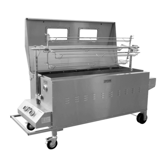
BPROASTER
DELUXE PIG ROASTER
ASSEMBLY INSTRUCTIONS
or call Customer Service at 1-888-287-6981, Monday-Friday, 8 AM - 4 PM
Advertisement

Related Manuals for Buffalo Tools BPROASTER


Summary of Contents for Buffalo Tools BPROASTER
- Page 1 BPROASTER DELUXE PIG ROASTER ASSEMBLY INSTRUCTIONS READ ALL INSTRUCTIONS AND WARNINGS BEFORE USING THIS PRODUCT. This manual provides important information on proper operation & maintenance. Every effort has been made to ensure the accuracy of this manual. These instructions are not meant to cover every possible condition and situation that may occur.
-
Page 2: Assembly Checklist
ASSEMBLY CHECKLIST Read all instructions thoroughly before proceeding. Find a large, clean area in which to assemble your oven. Refer to the parts list and assembly diagram as necessary. Assembly of this oven involves many large components. It is advisable to have two people assemble the unit. Tools required: A Philips crosshead or flat-bladed screwdriver and either a spanner or a pair of pliers. -
Page 3: Parts Diagram
PARTS DIAGRAM Page 3 of 11... - Page 4 PARTS AND HARDWARE LIST Description M5×10 Screw Roast cradle M6×12 Screw R Clip M6×35 Screw Roast cradle support Cooking Pans/Drip Pan M8×15 HEX Screw Triangle support ¢6 Lock Washer Meat prong ¢6 Flat Washer W Retainer U-Shaped fork assembly ¢13 Flat Washer Rotisserie shaft Split Lock Washer Rotisserie shaft front bracket assembly...
- Page 5 ASSEMBLY 1) Remove straps and box 2) Remove accessories 3) Remove the box that is lid. Sides will start to from box, and remove the stored inside the pig roaster. come apart. protective wrap which is covering the pig roaster. 4) Place a blanket or cardboard on the ground to protect the stainless steel, then rotate or flip...
- Page 6 ASSEMBLY (Continued) Placement of Lock & Flat Washers 7) Locate and install #20 and #21 wheel supports. Then install (#18) 6” wheels without brake on back end of roaster. Stop End 9) Install drip tray brace #26 8) Refer to the diagram (Upper 10) Slide the Drip tray onto brace.
- Page 7 ASSEMBLY (Continued) 12) Mount #25 motor 13) Install #14 Rear 14) Install the Roller Bolt support. Bracket Assembly. Note and Roller, follow the this has the Square slot. photo above. 15) Note the positioning 16) Install #24 motor. 17) Install #23 motor heat of the Rollers.
- Page 8 ASSEMBLY (Continued) Note: The diagrams list the positioning for Washers, Bolts, etc. 21) Attach the regulator hose (included) located under the Ref # 15 front side (thermostat side). Ref # 26 Ref # 20 Ref # 16 Ref # 13 / 13A Ref # 27 Ref # 21 Ref # B M6×12×6 PCS...
- Page 9 ASSEMBLY (Continued) Note: The diagrams list the positioning for Washers, Bolts, etc. Store U-Shape Pin Here When Not using Rotisserie U-Shape Pin Ref # 5 Ref # 9 Ref # 5 Ref # 22 Ref # 7 Ref # 6 Ref # 8 Ref # 7 Ref # 6 Ref # 3...
- Page 10 ASSEMBLY (Continued) Note: The diagrams list the positioning for Washers, Bolts, etc. Ref # 4 Ref # 4 Unscrew the igniter cap and insert a The thermocouple can move during the first cooking process. “AA” battery with the “ + “ end upwards. Simple repositioning of the probe by altering its position on the brass thread so it is nearer the flame.
- Page 11 ASSEMBLY (Continued) Familiarise yourself with the Spit To Motor Connector (U-Shape Pin). DO NOT LOSE THIS PIN. You will find two holes on the motor bracket where this pin can be stored when not in use. If stored outside, fit a rainproof cover over the oven when it is not in use. IM PO RTAN T Upon receipt, your oven will be covered in a thin layer of oil which is used in the manufacturing process.
Need help?
Do you have a question about the BPROASTER and is the answer not in the manual?
Questions and answers