Table of Contents
Advertisement
When calling for technical support..... ........
please have your serial numbers ready.
The Sensor and Instrument Serial Numbers are on the rear of the instrument, also see section
5.2.4.
Sensor Serial No.: _______________
Instrument Serial No.: _______________
Your Representative is:
COSA XENTAUR CORPORATION
84F Horseblock Road, Yaphank, NY 11980
Tel.: (631) 345-3434 - Fax.: (631)345-5349
Except as may be provided by contract, this document and all specifications and drawings contained
are the property of COSA XENTAUR Corporation, are issued in strict confidence, and shall not be
reproduced or copied, in any form or by any means, or used as the basis for the manufacture or sale
of apparatus, programs, or services without permission.
Check the Internet for updates; The latest revision of this manual is available in Adobe Acrobat
format at: http://www.COSAXENTAUR.com
Document No. XD0.01.D.0000, Rev E
Advertisement
Table of Contents

Related Manuals for Cosa XPDM


Summary of Contents for Cosa XPDM
- Page 1 Except as may be provided by contract, this document and all specifications and drawings contained are the property of COSA XENTAUR Corporation, are issued in strict confidence, and shall not be reproduced or copied, in any form or by any means, or used as the basis for the manufacture or sale of apparatus, programs, or services without permission.
- Page 2 The customer agrees that in accepting and using this instrument, Xentuar Corporation’s liability arising from or in any way connected with this instrument shall be limited exclusively to perform- ing a new calibration or replacement or repair of the instrument or sensor, at COSA XENTAUR’s sole option.
-
Page 3: Table Of Contents
XPDM Manual Table of Contents 1. Introduction ............................4 2. Precautions ............................5 3. Principle of Operation ........................6 4. Operating the XPDM ........................8 4.1. Sample Hook-up ........................8 4.1.1. Fittings ..........................8 4.1.2 Recommended Pipes ......................8 4.1.3. Sample conditioning ......................8 4.2. -
Page 4: Introduction
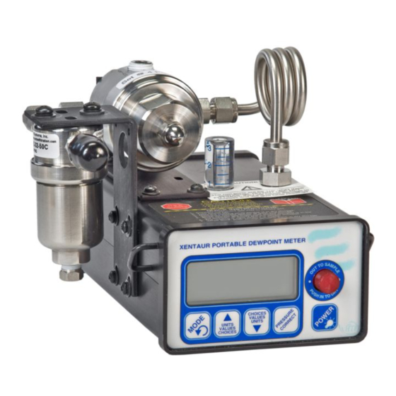
1. Introduction The XPDM is a portable, hand-held, microprocessor controlled, battery operated dew-point meter with built in dry-storage for the sensor. The instrument is ideally suited for all applications, where quick and precise measurements are required. Standard Equipment: Optional Equipment: 1. -
Page 5: Precautions
XTR-65W sensor which is water proof, but has a limited range, and a slower dry down response. . • Avoid high pressure: The XPDM has been designed for operation at pressures slightly above atmospheric, however each sample cell, sensor, piston, dry-storage assembly has been tested for pressures up to 120 PSI. -
Page 6: Principle Of Operation
11.Instrument Case 6. Spring loaded PTFE seals The drawing on the left shows the XPDM with the sensor in dry-storage position. The sen- sor is enclosed in a gas-tight container and surrounded by desiccant. The sample gas passes through the sample chamber and prepares the environment for measurement. - Page 7 A note about dry-storage The dry-storage consist of a stainless steel container filled with desiccant. The elec- tropolished stainless steel sensor guard slides between the dry-storage and the sample cell through a spring energized PTFE seal, assuring maximum possible gas tightness and minimum gas transport between the two chambers when the sensor is moved.
-
Page 8: Operating The Xpdm
4.1. Sample Hook-up 4.1.1. Fittings The XPDM can be hooked up to the sample gas using a variety of fittings, depending on the application. The instruments’ sample ports are 1/4” VCO® female, to assure proper seals for even the lowest dewpoint measurements. Depending on the application and needs, we recommend the use of one of the following methods of attachment: •... - Page 9 • Observe the change in dewpoint indication. The reading will be stable within about 3 minutes, if the dewpoint is increasing. A longer stabilization period will be required, if the dewpoint is decreasing. Make sure the reading has completely stabilized before taking the final reading. After the reading is taken, push the sensor actuator back into the dry-down position.
-
Page 10: The User Interface
5.0 The User Interface The user interface consists of a custom LCD display, an audio indicator, 5 push buttons and a sensor actuator. 5.1 Display Conventions 1. To display letters with the 7 segment numeric display, the following pseudo-alpha-numerics are used: Numbers: Letters: A B C D E F G H I J L N O P Q R S T U X Y Z... -
Page 11: Operating State
5.2 Operating State Refer to Appendix A for a flow diagram of the operating state. The XPDM is powered ON by pressing the ‘Power’ button until a beep is heard; to activate the backlight, continue to depress the ‘Power’ button until the backlight turns on. Keep in mind that with the backlight on the unit consumes about 5 times more power. -
Page 12: Viewing Temperature At The Sensor
correct buttons operate in the same manner as in the Sensor Pressure sub-state. Pressing the ‘Mode’ button changes the unit back to View/Set Sensor Pressure sub-state, and so forth. Note: The units leave the factory in the lock mode and must be unlocked before this procedure can take place (see section 5.3 #7 to unlock). -
Page 13: Set-Up State
5.3 Set-up State To enter the Setup State power-up the unit while depressing the Mode key. Refer to Appendix B for a flow diagram of the Set-up State. The set-up state provides the following nine capabilities: Testing the optional analog output: By pushing the up, down or pressure correct buttons, the user forces the analog output to its low, high and mid values, respectively. -
Page 14: Options
-79.1degC -110.4degF 0.0339LbsH2O/mmscf 0.625ppmV 0.00544g/m3 If an error condition exists the XPDM will respond to the question mark with a phrase describing the error: SensOpen or SensSaturated or SensShorted NOTE: Characters marked in bold are indications of sent or received strings. - Page 15 If the current loop is not being used, it is safe to connect the DB9 connector directly to a PC; pins 1&9 will not be damaged or cause damage. The RS-232 levels are generated by the instrument only when an RS-232 level is detected at the DB9 input. Therefore, when operating from a battery to conserve its power, disconnect the RS-232 cable unless necessary for the operation.
-
Page 16: Operating From An External Power Supply
6.3 Operating from an external Power Supply The external power connector is a 2mm power jack located on the rear of the unit. This input can accept either AC or DC power and is thus polarity independent. The unit requires 13VDC to 25VDC, when operating from external DC power. The unit requires 12VACrms to 25VACrms, when operating from external AC power. -
Page 17: Automatic Calibration
The instrument is calibrated at the factory with the shipped sensor, and does not need to be re-calibrated prior to use. Do not re-calibrate the unit unless you suspect a problem. The XPDM instrument takes advantage of the pre-designed saturation point of COSA XENTAUR HTF™ sensors. Because COSA XENTAUR HTF™ sensors saturate at a factory designed dew-point above +20°... -
Page 18: Changing Desiccant Cartridge And/Or Battery
Move the sensor actuator back and forth to make sure that the sensor moves in and out of the desiccant smoothly. Bottom view of the XPDM with cover open. The sample chamber and desiccant cartridge are shown cut open to facilitate an understanding of the mechanism and how it is assembled. -
Page 19: Changing The Battery
8.1 Changing the battery - When the unit displays “LO BAT” at start up, the battery should be replaced. - Only replace the battery in a safe area. - Never replace the battery when an explosive gas atmosphere is present - The user should observe the correct installation polarity of the battery as shown on the inside of the battery holder. -
Page 20: Special Messages, Warnings And Error Indications
Sensor is neither in nor out of desiccant Pull out or push in the sensor actuator I N . - / O U T Turn on message COSA XENTAUR (Greek “Ξ” = “X” ) X E N Turn off message, good-bye... -
Page 21: Apendix A: Flow Diagram Of User Interface In Operating State
Apendix A: Flow Diagram of User Interface in Operating State... -
Page 22: Appendix B: Flow Diagram Of User Interface In Setup State
Appendix B: Flow Diagram of User Interface in Setup State... -
Page 24: Appendix C: Releationship Of Instrument Reading And 4-20Ma Output When Lds Of H O/Million Standard Cft Or Ppmv Engineering Units Are Selected
Appendix C: Releationship of Instrument Reading and 4-20ma output when lds of H O/million standard cft or ppmv engineering units are selected . -
Page 25: Appendix D: Uncertainty In Lbs And Ppmv Calculations
Appendix D: Uncertainty in LBS and PPMV calculations... -
Page 26: Appendix E: Battery Life
Appendix E: Battery Life Note: The ATEX approved model is supplied with and must use a model GMBPower Battery, ER9V.
Need help?
Do you have a question about the XPDM and is the answer not in the manual?
Questions and answers