
Subscribe to Our Youtube Channel
Related Manuals for Cosa XENTAUR 9610CXc


Summary of Contents for Cosa XENTAUR 9610CXc
- Page 1 INSTALLATION, OPERATION AND MAINTENANCE MANUAL – 9610CXc™ INSTALLATION, OPERATION MAINTENANCE MANUAL 9610CXc™ Version: 1.5.2 Revision date: June 28 , 2024 CAL.01.D.9826 P a g e...
- Page 2 INSTALLATION, OPERATION AND MAINTENANCE MANUAL – 9610CXc™ Process Insights New York Texas Corporate Headquarters, Sales & Service Offices: Manufacturing Offices: 84G Horseblock Rd. Building 6, 14400 Hollister St. Suite 800-B Yaphank, NY 11980 Houston, TX 77066 Tel: 631-345-3434 Tel: 713-947-9591 Fax: 713-947-7549 E-mail: support.hou@process-insights.com...
- Page 3 INSTALLATION, OPERATION AND MAINTENANCE MANUAL – 9610CXc™ Table of Contents 1. INTRODUCTION ............................7 1.1. INTRODUCTION ..........................7 1.1.1. Purpose of the analyzer ......................... 7 1.2. SPECIFIC CONDITIONS OF USE ......................7 1.3. THE 9610CXc™ ANALYZER ........................7 1.3.1. Oven with oxygen sensor ....................... 8 1.3.2.
- Page 4 INSTALLATION, OPERATION AND MAINTENANCE MANUAL – 9610CXc™ 1.8.1 Purpose ............................. 21 1.8.2. Operation ............................22 1.9 Flow alarm ............................... 22 2.0 System maintenance ..........................23 2. INSTALLATION ............................25 2.1. GENERAL ..............................25 2.2. STORAGE ..............................25 2.3. PLACEMENT ............................25 2.3.1.
- Page 5 INSTALLATION, OPERATION AND MAINTENANCE MANUAL – 9610CXc™ 3.3.2. Operation Menu ........................37 3.3.3. Measurement Menu ........................38 3.3.4. Output Menu ..........................39 3.3.5. Communications Menu ......................41 3.3.6. System Menu ..........................42 3.3.7. Reset Alarms Menu ........................44 3.4. TEMPERATURE CONTROLLED OVEN ....................44 3.4.1.
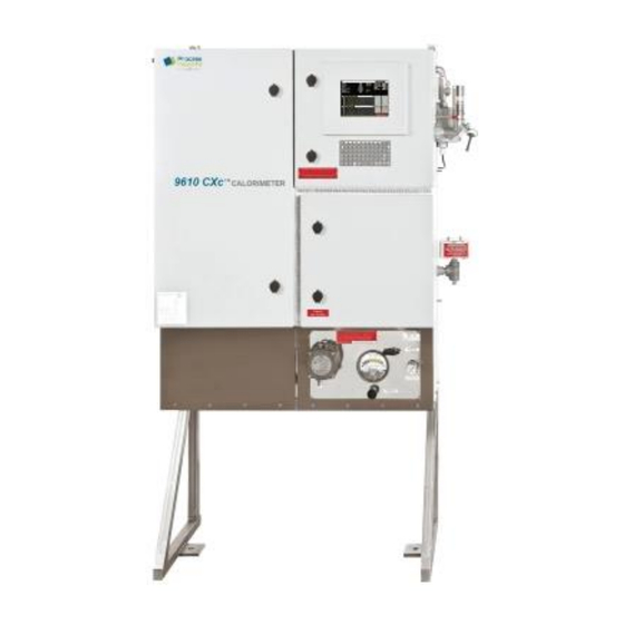
- Page 6 INSTALLATION, OPERATION AND MAINTENANCE MANUAL – 9610CXc™ 1. INTRODUCTION 1.1. INTRODUCTION 1.1.1. Purpose of the analyzer The continuous 9610CXc™ analyzer determines online the Wobbe-index of a gas. The 9610CXc™ can be used both, as feed forward and feedback analyzer for gases mixing or as a feed forward analyzer for burning control.
- Page 7 INSTALLATION, OPERATION AND MAINTENANCE MANUAL – 9610CXc™ • Oven compartment Optionally the 9610CXc™ can be built in an explosion proof execution. In explosion proof execution, the analyzer is protected with a purge system. WARNING - Potential Electrostatic Charging Hazard. Due to the materials construction of the viewing port, there is a potential to build up an electrostatic charge across the surface.
- Page 8 INSTALLATION, OPERATION AND MAINTENANCE MANUAL – 9610CXc™ gas and the air are equalized in a heat exchanger. The gas and air temperature are still at surrounding temperatures, however, as long as gas and air fluctuate to the same extent this hardly influences the mixing proportion. In case of large surrounding temperature fluctuations, the calibration sequence has to be performed more often.
- Page 9 INSTALLATION, OPERATION AND MAINTENANCE MANUAL – 9610CXc™ • Three-point calibration This method uses three calibration gases and is mandatory for a dual range analyzer. The medium range calibration gas must be in the middle of the measuring range. All three calibration methods can be performed both manually and automatically: •...
- Page 10 INSTALLATION, OPERATION AND MAINTENANCE MANUAL – 9610CXc™ The three-point calibration/validation procedure will be executed as followed: 1. Analyzer activates calibration/validation contact. 2. The procedure pauses for the specified “Calibration Start Delay” time for the external host to prepare for calibration/validation. 3.
- Page 11 INSTALLATION, OPERATION AND MAINTENANCE MANUAL – 9610CXc™ Make Process Insights Service Natural gas, fuel-gas, biogas, etc. Wobbe index 0-2730 BTU/scf (0-102 MJ/Nm Ranges span 0-1150 BTU/scf (43 MJ/Nm ) (selectable) CARI 0-20, span 0-10 Accuracy ± 0.4% of measuring value natural gas Repeatability ±0.7 BTU/scf (±0.03 MJ/Nm Drift...
- Page 12 INSTALLATION, OPERATION AND MAINTENANCE MANUAL – 9610CXc™ 1.6.3. Installation Mounting Freestanding Frame. Dimensions 40.8 x 40.8 x 16.3 inches (1000 x 1000 x 400 mm) Weight Up to 450 lbs (204 kg). Shipping weight 750 lbs (340 kg) 50 to 104º F (10 to 40 °C) Extended range to -40 to 140°F (-40 to 60°C) With Heater and Vortex Cooler options in electronics cabinet Ambient temperature...
- Page 13 INSTALLATION, OPERATION AND MAINTENANCE MANUAL – 9610CXc™ 1.7 X-Purge Option 1.7.1. Purpose The 9610CXc™ Calorimeter is protected by a Pepperl & Fuchs X-purge unit. The purge Type X and Ex px purge pressurization system protects general-purpose equipment mounted in a standard enclosure so that it can be located and operated in a hazardous area.
- Page 14 INSTALLATION, OPERATION AND MAINTENANCE MANUAL – 9610CXc™ system such as purge time, flow rates, pressures, and enclosure size are easily programmable. Additional features allow Class I and Class II operation, inputs for system bypass, enclosure power on/off, temperature overload and activation of Rapid Exchange flow for cooling or auxiliary relay for separate cooling source, delay power shutdown, and much more.
- Page 15 INSTALLATION, OPERATION AND MAINTENANCE MANUAL – 9610CXc™ • EPV-6000 vent with spark arrestor screen • 1½” sealing nut with gasket for attachment of vent to customer’s enclosure • One 5 meter, quick disconnect cable; blue (denoting I.S.), for connection to I.S. termination board inside X-Purge control unit The X-Purge control unit and vent are mounted to the calorimeter enclosure.
- Page 16 INSTALLATION, OPERATION AND MAINTENANCE MANUAL – 9610CXc™ there is an internal system fault. 1.7.2.4. Pneumatic Manifold with I.S. Solenoid • Manifold with I.S. solenoid valve: The manifold system is mounted on the 6000 control unit providing a needle valve to set enclosure pressure and an I.S. solenoid valve that is used for purging (Rapid Exchange).
- Page 17 INSTALLATION, OPERATION AND MAINTENANCE MANUAL – 9610CXc™ • 20 SCFM @ 3.1” w.c., (565 l/min @ 77 mm w.c.) • 30 SCFM @ 3.4” w.c., (850 l/min @ 86 mm w.c.) The 9610CXc™ uses the first setting of 5 SCFM @ 1.3” w.c. to establish the purge within the enclosures.
- Page 18 INSTALLATION, OPERATION AND MAINTENANCE MANUAL – 9610CXc™ manually when purging and manually disengage when a successful purging is complete. • SA – Semiautomatic mode requires the operator to engage the manifold solenoid valve manually when purging. The EPCU will automatically disengage when a successful purging is complete.
- Page 19 INSTALLATION, OPERATION AND MAINTENANCE MANUAL – 9610CXc™ 1.7.2.11. EPV-6000 I.S. Relief Vent The EPV-6000 vent exhausts excess pressure from the enclosure if the pressure within the enclosure is above 1.0” w.c. and measures flow and pressure during operation. The X-Purge vent has a pressure transducer and thermal flow sensor that is connected to the 6000 EPCU and is intrinsically safe through the galvanic isolation barrier within the EPCU.
- Page 20 INSTALLATION, OPERATION AND MAINTENANCE MANUAL – 9610CXc™ 1.8 Z-Purge Option 1.8.1 Purpose The 9610CXc™ Calorimeter is protected by a Pepperl & Fuchs’ Bebco EPS system type Z rapid exchange purging system, model 1002. It allows the use of general purpose or nonrated non-rated electrical or electronic devices, with exception to devices that produce excessive heat, utilize combustible gas, or expose arcing contacts to the hazardous atmosphere, in NEMA (National Electrical Manufacturers Association) 4 or 12 enclosures in...
- Page 21 INSTALLATION, OPERATION AND MAINTENANCE MANUAL – 9610CXc™ • Regulator • EXP pressure loss alarm switch 1.8.2. Operation With the inert gas supply connected, enclosure power deenergized and alarm system energized (if utilized). 1. Carefully read start-up instruction nameplate on system. 2.
- Page 22 INSTALLATION, OPERATION AND MAINTENANCE MANUAL – 9610CXc™ The PurgemasterTM meter used in The 9610CXc™ Calorimeter is equipped with a min alarm contact. The alarm sensor is suitable for hazardous location because the sensors are intrinsically safe when used with the switching amplifier. The 9610CXc™...
- Page 23 INSTALLATION, OPERATION AND MAINTENANCE MANUAL – 9610CXc™ for the maintenance schedule. Regular Maintenance Drain the protection system regulator frequently and clean system with nonsolvent cleaning agents only. Long-Term Maintenance Calibrate the enclosure pressure indicator to 0 inches by venting the purge pressure reference port and the protected enclosure to atmosphere and adjusting the calibration screw in the lower center portion of the indicator’s face.
- Page 24 INSTALLATION, OPERATION AND MAINTENANCE MANUAL – 9610CXC™ 2. INSTALLATION 2.1. GENERAL Upon receipt and unpacking of the 9610CXc™ a visual inspection must be carried out to check for any visual damage, caused by transport. Any damage must be reported immediately to: Process Insights CORPORATION Texas Office: Building 6, 14400 Hollister Street Suite 800-B...
- Page 25 INSTALLATION, OPERATION AND MAINTENANCE MANUAL – 9610CXc™ 2.3.2. 9610CXc™ in general purpose execution The 9610CXc™ is mounted to a freestanding stainless-steel frame. Fixing lugs are located on each corner of the cabinet. Fixings used must be suitable for the weight of the 9610CXc™...
- Page 26 INSTALLATION, OPERATION AND MAINTENANCE MANUAL – 9610CXc™ another correct size wrench for 1- 1/4 turn for 1/4" fittings, 3/4 turn for 1/8" fittings. Watch the marks. • Before connecting the tubing to the analyzer they must be blown through with dry nitrogen or instrument air to remove all particles. •...
- Page 27 INSTALLATION, OPERATION AND MAINTENANCE MANUAL – 9610CXc™ 2.4.2. Sample supply The sample supply line must be heat-traced and/or insulated to keep the gas above dew point. Check your sample data for required temperature. Sample inlet connection on the analyzer is identified with a tag-plate. The sample connection on the analyzer is for 1/8”...
- Page 28 INSTALLATION, OPERATION AND MAINTENANCE MANUAL – 9610CXc™ 2.5.2. Analyzer electronics (NEC US application). The power must be connected on the interference filter inside the electronics cabinet. The cable must lead into the analyzer through a suitable approved conduit and conduit adapters.
- Page 29 INSTALLATION, OPERATION AND MAINTENANCE MANUAL – 9610CXc™ side, the connecting fittings can be squirted with soap in order to detect any possible leaks. When bubbles appear, this indicates a leak and the tube concerned must immediately be closed off at the supply point. Inspect the fitting and tube, replace components when necessary.
- Page 30 INSTALLATION, OPERATION AND MAINTENANCE MANUAL – 9610CXc™ adjusted based on the application. After this throttle back the output of the analyzer flow to 40 liter/hr (660 CCM or 1.4 CFH) using the needle valve on flow meter tagged "Analyzer flow". 3.1.6.
- Page 31 INSTALLATION, OPERATION AND MAINTENANCE MANUAL – 9610CXc™ After this adjustment, the plug must be re-installed, and the offset can be checked. The offset adjustment can be checked by reading the air and gas pressure indicators. This operation must be repeated until the desired residual oxygen concentration is reached.
- Page 32 INSTALLATION, OPERATION AND MAINTENANCE MANUAL – 9610CXc™ ESC. Then To enter the main menu screen, press screen now presents some functions that can be selected by the cursor keys or by typing the number associated to the menu item. To resume normal operation, press until the main screen to appear.
- Page 33 INSTALLATION, OPERATION AND MAINTENANCE MANUAL – 9610CXc™ cal gas 3 Digital output driving high value calibration gas air actuator range 1 (optional) Extended range execution indicating second mixing chamber is selected for dual range option stream 1 (Standard) Indicating process stream 1 selected stream 2 (optional) Indicating process stream 2 selected Stream sw...
- Page 34 INSTALLATION, OPERATION AND MAINTENANCE MANUAL – 9610CXC™ 35 | P a g e...
- Page 35 INSTALLATION, OPERATION AND MAINTENANCE MANUAL – 9610CXC™ 36 | P a g e...
- Page 36 INSTALLATION, OPERATION AND MAINTENANCE MANUAL – 9610CXC™ 3.3. P ROGRAMMING ENUS The paragraph numbers correspond with the key sequence from the ‘menu tree’. In this way it is easy to see how a specific menu is reached. One exception is the measuring menu, this is reached from the main screen by either the ENTER key.
- Page 37 INSTALLATION, OPERATION AND MAINTENANCE MANUAL – 9610CXc™ 3.3.3. Measurement Menu 38 | P a g e...
- Page 38 INSTALLATION, OPERATION AND MAINTENANCE MANUAL – 9610CXc™ 3.3.4. Output Menu 39 | P a g e...
- Page 39 INSTALLATION, OPERATION AND MAINTENANCE MANUAL – 9610CXc™ 40 | P a g e...
- Page 40 INSTALLATION, OPERATION AND MAINTENANCE MANUAL – 9610CXc™ 3.3.5. Communications Menu Submenus 1-3 with default communication settings 41 | P a g e...
- Page 41 INSTALLATION, OPERATION AND MAINTENANCE MANUAL – 9610CXc™ 3.3.6. System Menu 42 | P a g e...
- Page 42 INSTALLATION, OPERATION AND MAINTENANCE MANUAL – 9610CXc™ Passwords: • USER: 1234 ADMIN: 9999 • Display Menu 43 | P a g e...
- Page 43 INSTALLATION, OPERATION AND MAINTENANCE MANUAL – 9610CXc™ 3.3.7. Reset Alarms Menu 3.4. TEMPERATURE CONTROLLED OVEN 3.4.1. Furnace temperature control unit The zirconia cell must operate at a temperature above 600ºC. For optimal performance, a set-point temperature of 812ºC was chosen. The oven that serves as the heating device for the zirconia cell is made of a metal wire-wound heating element.
- Page 44 INSTALLATION, OPERATION AND MAINTENANCE MANUAL – 9610CXc™ temperature set-point. The oven needs about half an hour to heat up to 812ºC. Normal on/off-ratio is about 85%. This allows for a stable temperature control and long lifetime of the oven (typically 2 – 8 years). NOTE: Set oven temp to 812ºC &...
- Page 45 INSTALLATION, OPERATION AND MAINTENANCE MANUAL – 9610CXc™ 4. PREVENTIVE MAINTENANCE 4.1. WEEKLY, MONTHLY, THREE (3) MONTH MAINTENANCE 4.1.1. Filters Inspect three (3) filters, the pressure regulator air filter, gas filter, and coalescing filters, for signs of moisture, water, or liquids. If there is anything that indicate signs of moisture and/or liquids, these filters should be replaced.
- Page 46 INSTALLATION, OPERATION AND MAINTENANCE MANUAL – 9610CXc™ 4.3. T ROUBLESHOOTING Breakdown -> fault report Test Action No air pressure -> flow alarm tube fracture, leak in the system Check for leak Replace tube Measuring pressure behind Open valve for reducing valve For Z-purge reducing valve (for z-purge) tagged “air supply”...
- Page 47 INSTALLATION, OPERATION AND MAINTENANCE MANUAL – 9610CXc™ 4.4. REPLACEMENT OF RESIDUAL OXYGEN SENSOR AND CELL HOUSING Before going any further make sure that the oven has been disconnected and cooled off so that no physical injury can occur caused by coming into contact with any parts which may still be hot.
- Page 48 INSTALLATION, OPERATION AND MAINTENANCE MANUAL – 9610CXc™ 3. Loosen ½” x ½” x ¼” Reducing Union Tee and remove four (4) #10-32 screws. 4. Slowly remove the oven together with the thermal couple, cell housing, oxygen sensor, and wiring. Lay the oven down on the bottom of the oven compartment. ! Caution Care must be taken as it may damage the wire connectors.
- Page 49 INSTALLATION, OPERATION AND MAINTENANCE MANUAL – 9610CXc™ 6. Remove the 1/8” T x 1/8” FNPT elbow fitting and then slide the cell housing out of the oven. Caution O2 sensor and cell housing may be melted together due to the excessive heat inside the oven.
- Page 50 INSTALLATION, OPERATION AND MAINTENANCE MANUAL – 9610CXc™ 8. Mark the ½” tube at the internal shoulder of ½” x ½” x ¼” Reducing Union Tee. 51 | P a g e...
- Page 51 INSTALLATION, OPERATION AND MAINTENANCE MANUAL – 9610CXc™ 9. Remove the oven together with the cell housing from the oven compartment back plate. Remove the cell housing out of the oven. Use an appropriate cutting tool to trim off the ½” tube of the cell housing at the mark. Caution Burrs created during the cutting process must be removed using the deburring tool or a file prior to assemble the cell housing.
- Page 52 INSTALLATION, OPERATION AND MAINTENANCE MANUAL – 9610CXc™ 12. Continue to assemble the rest of components in the reverse order. 53 | P a g e...
- Page 53 INSTALLATION, OPERATION AND MAINTENANCE MANUAL – 9610CXc™ 5. MODBUS REGISTER LIST 5.1. COIL REGISTERS 54 | P a g e...
- Page 54 INSTALLATION, OPERATION AND MAINTENANCE MANUAL – 9610CXc™ 5.2. DISCRETE INPUT REGISTERS 55 | P a g e...
- Page 55 INSTALLATION, OPERATION AND MAINTENANCE MANUAL – 9610CXc™ 5.3. INPUT REGISTERS 56 | P a g e...
- Page 56 INSTALLATION, OPERATION AND MAINTENANCE MANUAL – 9610CXC™ 5.4. H OLDING EGISTERS 57 | P a g e...
- Page 57 INSTALLATION, OPERATION AND MAINTENANCE MANUAL – 9610CXc™ 58 | P a g e...
- Page 58 INSTALLATION, OPERATION AND MAINTENANCE MANUAL – 9610CXc™ 59 | P a g e...
- Page 59 INSTALLATION, OPERATION AND MAINTENANCE MANUAL – 9610CXc™ 60 | P a g e...
- Page 60 INSTALLATION, OPERATION AND MAINTENANCE MANUAL – 9610CXc™ 61 | P a g e...
- Page 61 INSTALLATION, OPERATION AND MAINTENANCE MANUAL – 9610CXc™ 62 | P a g e...
- Page 62 INSTALLATION, OPERATION AND MAINTENANCE MANUAL – 9610CXc™ 63 | P a g e...
- Page 63 INSTALLATION, OPERATION AND MAINTENANCE MANUAL – 9610CXc™ 64 | P a g e...
- Page 64 INSTALLATION, OPERATION AND MAINTENANCE MANUAL – 9610CXc™ 65 | P a g e...
- Page 65 INSTALLATION, OPERATION AND MAINTENANCE MANUAL – 9610CXc™ 66 | P a g e...
- Page 66 INSTALLATION, OPERATION AND MAINTENANCE MANUAL – 9610CXc™ 67 | P a g e...
- Page 67 INSTALLATION, OPERATION AND MAINTENANCE MANUAL – 9610CXc™ 68 | P a g e...
- Page 68 INSTALLATION, OPERATION AND MAINTENANCE MANUAL – 9610CXC™ 5.4. VARIABLE LIST 69 | P a g e...
- Page 69 INSTALLATION, OPERATION AND MAINTENANCE MANUAL – 9610CXC™ 6. INSTALLATION DRAWING 70 | P a g e...
- Page 70 INSTALLATION, OPERATION AND MAINTENANCE MANUAL – 9610CXC™ 7. ORDERING OF SPARE PARTS All spare parts may be ordered quoting number and specification from: PROCESS INSIGHTS CORPORATION New York Texas Corporate Headquarters, Manufacturing Offices: Sales & Service Offices: 84G Horseblock Rd. Building 6, 14400 Hollister Street Yaphank, NY 11980 Suite 800-B...
- Page 71 INSTALLATION, OPERATION AND MAINTENANCE MANUAL – 9610CXC™ 3-5 Year CAL.98.M.0009 Tee filter 1 Year CAL.98.M.0025 Filter Element for Tee Filter 1 Year XD0.98.M.5023 Coalescing Filters 10/Pack SPECIFIC GRAVITY CELL Low Temp Density Cell Assembly 5+ Year CAL.S4.M.10003 c/w Density Cell Converter Board GAS &...
- Page 72 INSTALLATION, OPERATION AND MAINTENANCE MANUAL – 9610CXC™ 5 Year CAL.98.E.0022 I/O module 5 Year CAL.98.E.0023 I/O module 5 Year CAL.70.M.0032 Heater 200 Watt for electronics CPU Vortex (required to order CAL.98.E.0097 5 Year CAL.10.E.0010 & CAL98.E.0106 with this CPU) Flash Disk Module (required to order CAL.98.E.0106 programming with flash 5 Year CAL.98.E.0097...
- Page 73 INSTALLATION, OPERATION AND MAINTENANCE MANUAL – 9610CXC™ 3 Year CAL.98.M.0055 Pressure Gauge, 0-60PSIG, mid-temp 5 Year CAL.98.M.0237 Manifold Block 3-Module 3-5 Year CAL.98.M.0315 Flow Indicator 10-1000 CCM 3-5 Year CAL.98.M.0316 Flow Indicator 1-30LPM SS Valve 3-5 Year CAL.98.M.0008 Flame Arrestor for SCS 5 Year CAL.98.M.0117 Relief Valve, 0.2-3.5 Bar...
- Page 74 INSTALLATION, OPERATION AND MAINTENANCE MANUAL – 9610CXC™ Cell Housing with screens ½” vent tube 3-5 Year CAL.98.M.9765 Cell Housing with screens 1/4” vent tube – 3-5 Year CAL.98.M.0030 9600 only 5 Year CAL.18.E.0003 Inner cell connector cable 5 Year CAL.18.E.0004 Outer cell connector cable 5 Year CAL.98.M.0343...
- Page 75 INSTALLATION, OPERATION AND MAINTENANCE MANUAL – 9610CXC™ 8. LABELS 76 | P a g e...
Need help?
Do you have a question about the XENTAUR 9610CXc and is the answer not in the manual?
Questions and answers