
Related Manuals for Awite AWIECO


Summary of Contents for Awite AWIECO
- Page 1 Original Instruction Manual Original Instruction Manual (Version: 12.0) (Version: 12.0)
- Page 2 Awite Bioenergie GmbH Grünseiboldsdorfer Weg 5 85416 Langenbach/Niederhummel, Germany Phone: +49 8761 / 72 162 - 0 Fax: +49 8761 / 72 162 - 11 Email: info@awite.com http://www.awite.com © 2020 Awite Bioenergie GmbH Errors and changes reserved...
-
Page 3: Table Of Contents
5.2.1 Main Switch Mains Disconnection Facility............. 21 5.2.2 Terminal boxes for electrical connections.............. 21 5.2.2.1 Terminal box AwiECO.................... 22 5.2.2.2 Connection Cable 100–240 V for Power Supply............22 5.2.2.3 Connection cable for DI (digital inputs) and DO (digital outputs)......22 5.2.2.4 Connection cable for AI (analogue inputs) and AO (analogue outputs).... - Page 4 Analogue outputs....................25 5.2.5 Information on Cable and Lines Routing..............25 5.2.6 Connection of analysis gas lines................26 5.2.6.1 Gas Inlets AwiECO....................26 5.2.6.2 Extraction Points for Analysis Gas.................27 5.2.6.3 Laying of Analysis Gas Lines.................28 5.2.6.4 Exhaust air – Discharge of the Measuring Gas............. 28 5.2.7...
-
Page 5: Preface
Instruction Manual. Please operate and service your gas analysis system based on the information in this Instruction Manual. The Instruction Manual for the Awite – Gas Analysis System consists of two parts: Part A: Product Description, Installation and Operation... -
Page 6: Identification
Identification Identification This Instruction Manual is intended for Awite Bioenergie GmbH gas analysis systems of the respective series specified on the cover sheet. The type plate on the right hand side panel of the device indicates the device type, the required voltage supply and the rated output. -
Page 7: Safety Instructions Part A
Safety Instructions Part A Safety Instructions Part A The device is only designed for situations of intended use. A non-intended use can lead to personal injury and property damage. Only use the device as intended. The device measures combustible or explosive gases and is installed in their environment. There is a potential risk of spread or ignition of a hazardous atmosphere. - Page 8 In the event of the error messages "potentially dangerous atmosphere" or "risk of explosion" as well as with loose hose ends, porous hoses or other leaks that lead to an explosion hazard, disconnect the device from the gas supply and shut it down. Contact Awite or an Awite contract partner.
- Page 9 Safety Instructions Part A The device contains fuses that are under electrical voltage. Danger to life by electric shock. Replace the fuses only in a non-energized state. Observe electrical safety regulations. Leakages in the AwiCONTAINER may create a hazardous atmosphere. The ventilation grilles are important in order to dilute the air in case of leakages.
-
Page 10: Product Description
They are used without any additional pressure reducing measures for measuring biogas with a maximum of 20 mbar of underpressure or overpressure. The suitability for use in safety- critical applications must be assessed by the user for each case. Reliability data can be provided by Awite if required. -
Page 11: Device Category According To Atex Classification
Product description Device Category According to ATEX Classification Applies only within the EU and in countries in which the ATEX Directive (2014/34/EU) also applies. The ATEX marking is located on the left outside of the casing. 4.2.1 Device category not intended for installation in an Ex-zone Marking per ATEX with II 2/- G IIA Gas-carrying pipes with inflammable or explosive gas of explosion group IIA (e.g. -
Page 12: Safety Device For Monitoring The Interior Space
The measuring head is integrated in Awite Process Analysis. The evaluation unit which delivers the shutdown signal must be installed outside of an Ex-zone. The disconnection of the power supply to the Awite process analysis device takes place on site. The gas warning device is supplied with 24 VDC on site. -
Page 13: Description Of The Gas Analysis System And Dimensions
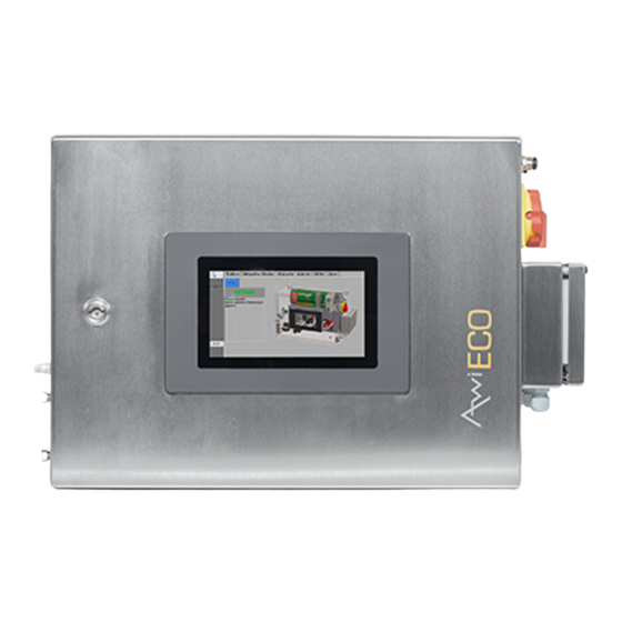
Mounting dimensions [mm] Width Height Depth AwiECO The analysis gas lines are routed to the system from the left hand side via the condensate traps for the manual emptying of the system. Pressure-resistant pipes are recommended as analysis gas lines: –... - Page 14 Product description Figure 1: AwiECO including condensate traps on the outside The equipment shown here serves as an example, as the components are individually assembled according to customer requirements. 1. Main switch 9. Exhaust air 2. Terminal box 10. Supply of analysis gas 3.
- Page 15 Product description Figure 2: Assemblies in the gas analysis system AwiECO The equipment shown here serves as an example, as the components are individually assembled according to customer requirements. 1. Main switch 11. Terminals shielding sensors 2. Line filter 12. Water sensor AwiH 3.
-
Page 16: Ambient Conditions And Limits For Operation And Storage
Ambient Conditions and Limits for Operation and Storage Although the Awite gas analysis systems are designed for use under rough conditions, some requirements concerning the location and environmental conditions should be met in order to obtain a high accuracy of measurement and to avoid damaging the system. -
Page 17: Measuring Gas, Fresh Air And Exhaust Air Requirements
For AwiECO, the following applies: If there is a possibility of larger amounts of condensate in the measuring gas pipe and if the condensate traps cannot be checked on a regular basis, an additional gas cooler must be installed. -
Page 18: Zone Division
Product description 4.5.1 Zone division Inside the measuring gas pipes and inside the gas analysis system there are only very small amounts of gas, whose volume is far below hazardous amounts. Therefore no Ex-zone obtains in this case. Whether there is an Ex-zone around the gas analysis system or its pipes or not depends on the probability of the occurrence of an explosive gas mixture. -
Page 19: Release Of Potentially Toxic And Harmful Gases
Product description The pipes inside are considered to be technically leak-tight. Due to the way they are constructed, some sensors can only be used with plug connections which are secured with spring terminals. As an additional safety measure, the high-quality methane sensor that is integrated in the gas analysis system is used to track down possible leaks. -
Page 20: Preparing The Gas Analysis System For Use
Preparing the Gas Analysis System for Use Preparing the Gas Analysis System for Use WARNING This is a complex measuring and control system. Incorrectly performed installation, electrical installation, initial operation, or maintenance can lead to hazards and possibly even to death due to electric shock or risk of explosion. -
Page 21: Main Switch Mains Disconnection Facility
Check the connections afterwards. The Awite gas analysis system includes a terminal box for external connection. The terminal box offers connections for the following components: –... -
Page 22: Terminal Box Awieco
Preparing the Gas Analysis System for Use 5.2.2.1 Terminal box AwiECO Figure 3: Terminal box Gas Analysis System AwiECO The terminal box illustrated here serves as an example only, as the number of feed-through terminals depends on the respective system setup. -
Page 23: Connection Cable For Ai (Analogue Inputs) And Ao (Analogue Outputs)
Preparing the Gas Analysis System for Use 5.2.2.4 Connection cable for AI (analogue inputs) and AO (analogue outputs) Speci cations Connection Cable: AWG21 (metric equivalent 0.5mm²) • 75°C / copper wire only (75°C / copper) • shielded / twisted in pairs •... -
Page 24: Data Transmission Of Signals
Preparing the Gas Analysis System for Use 5.2.4 Data transmission of signals There are various possibilities for data transmission. If the connection to the process control is done via a bus connection (e.g. Ethernet, Profibus DP, serial interface), the corresponding interface is found on the right hand side of the device casing. -
Page 25: Analogue Outputs
Preparing the Gas Analysis System for Use – Set switch on connector to ON/OFF. – Plug connector back into Profibus module, tighten safety screws, close device door 5.2.4.2 Analogue outputs The voltage supply for the analogue outputs takes place via the gas analysis system. A galvanic separation of the potentials at the recipient's end is necessary. -
Page 26: Connection Of Analysis Gas Lines
The exhaust air and condensate lines are also connected by hose screw or pipe screw connections. Fig. 5 show the allocation of the gas inlets. 5.2.6.1 Gas Inlets AwiECO Figure 5: Allocation of the gas inlets and exhaust air and for AwiECO Connection no. Description Connection to measuring point 1 2 (optional) -
Page 27: Extraction Points For Analysis Gas
Pressure: If the system pressure at the extraction point exceeds 20 mbar of relative high pressure, then additional fine pressure regulators have to be used (provided by Awite) which produce a stable output pressure of approx. 5 mbar of relative high pressure at a maximum of 400 mbar of relative high pressure at... -
Page 28: Laying Of Analysis Gas Lines
Preparing the Gas Analysis System for Use The analysis gas lines are led from the extraction point to the condensate traps in front of the gas analysis system (Fig. Figure 7: Schematic layout of the extraction points for analysis gas – Exemplary representation 5.2.6.3 Laying of Analysis Gas Lines... - Page 29 Preparing the Gas Analysis System for Use duct, which could lead to blockage by freezing in winter. The customer must prepare a corresponding feed through the wall above the gas analysis system (diameter of approx. 25mm). CAUTION The exhaust gas may be combustible and toxic. This may lead to fire, explosion and poisoning. Do not release the exhaust inside the building unless an appropriate controlled ventilation facility exists.
-
Page 30: Installation Of Humidity And Flow Sensor Awiflow
For details and prices please contact Awite. There must also be sufficient space (approx. 600mm from the pipe) for installation or removal of the sensor. The sensor should be positioned in such a way that the measuring tips are centered in the pipe, the flow direction arrow points in the flow direction of the gas, and the flattenings on the sensor shaft are parallel to the pipeline. - Page 31 But there is always the possibility of changed circumstances, which might require other factors. Therefore Awite shall not be liable for any deviations of the ow pro les. Figure 10: Inlet and Outlet Sections Flow Sensor AwiFLOW...
-
Page 32: Initial Operation
Preparing the Gas Analysis System for Use with flow conditioner 9 x pipe Ø 2 x pipe Ø Recommendation for a Setup with an Extension in the Inlet or Outlet Section < 150mm 20 x pipe Ø 10 x pipe Ø Fig. -
Page 33: Handling Of The Gas Analysis System
Handling of the Gas Analysis System Handling of the Gas Analysis System The gas analysis system may only be operated by personnel who have been authorized and instructed by the operator of the system. The instructions of this Instruction Manual have to be strictly adhered to. The state of the device has to be checked on a regular basis and error messages need to be addressed. -
Page 34: Calibration
3–6 months is recommended. The calibration can be carried out directly on-site by Awite or an Awite partner. Please contact Awite for further information. -
Page 35: Condensate Traps
The operating safety of the gas analysis system can only be maintained by using original parts or approved spare parts for every repair operation that is carried out and by adhering closely to the instructions in this manual and the repair instructions. Spare parts lists are available at Awite. -
Page 36: Disposal
Handling of the Gas Analysis System Disposal For a small fee, Awite is prepared to take back any Awite devices that need to disposed off and use them for further industrial processing. Product Liability Awite does not assume liability for damages caused by faulty measuring values. -
Page 37: Technical Data And Sensor Accuracy
From these figures it is possible to calculate the measurement uncertainties based on the uncertainty of the calibration gases, the calibration intervals, and the ambient temperature. If required, more comprehensive material on the subject of measurement accuracy is available at Awite. - Page 38 Technical Data and Sensor Accuracy Table 3: Measuring uncertainties without uncertainty of the calibration gas. The uncertainty wasdetermined at the calibration point. Values that have been conservatively extrapolated to themeasuring range end value are indicated in brackets (worst case) Measured physical Calibration Standard un-...
- Page 39 Technical Data and Sensor Accuracy Measured physical Calibration Standard un- Standard un- Standard uncer- component unit point (measur- certainty u2 certainty u3 tainty u4 right ing range end at delivery after 1 year after calibration value) +/– 10°C +/– 10°C +/–...
-
Page 40: Annex
Annex Annex CE Declarations of Conformity The gas analysis system can optionally be designed to be installed in the potentially explosive zone 2. Which declaration applies to the respective device can be determined using the marking on the left side of the device. - Page 41 Prozessanalyse-System, Process analysis system Typenbezeichnung, Type designation: Serie 10, Series 10 (AwiFLEX Cool+, AwiFLEX Cool+ XL und AwiECO) Das bezeichnete Gerät inklusive Zubehör entspricht den aufgeführten EU-Richtlinien und Normen. The denoted device including accessories corresponds to the listed EU guidelines and standards.
-
Page 42: Zone
Prozessanalyse-System, Process analysis system Typenbezeichnung, Type designation: Serie 10, Series 10 (AwiFLEX Cool+, AwiFLEX Cool+ XL und AwiECO) Das bezeichnete Gerät inklusive Zubehör entspricht den aufgeführten EU-Richtlinien und Normen. The denoted device including accessories corresponds to the listed EU guidelines and standards. -
Page 43: Iec - Conformity Declaration
Such pipes are used inside the Awite process analysis systems. For gases of group IIA (Methane) it is recommended to attach only pipes to the designated and appropriate place of the Awite de- vice with an inner diameter of maximal 4 mm and a minimal length of 11 cm. This pipe section can be defined as "no zone" ac- cording to IEC 60079-10. -
Page 44: Certificat Tüv Süd Ul - Csa 61010-1-2012
Annex Certificat TÜV SÜD UL - CSA 61010-1-2012...
Need help?
Do you have a question about the AWIECO and is the answer not in the manual?
Questions and answers