Advertisement
Quick Links
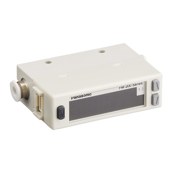
Integrated Indicator Type for Gas Flow Sensor
FM-200 Series
D2-255025-A
Thank you very much for purchasing Panasonic products. Please read this Instruc-
tion Manual carefully and thoroughly for the correct and optimum use of this product.
Kindly keep this manual in a convenient place for quick reference.
Never use this product in a device for personnel protection.
In case of using devices for personnel protection, use products which meet laws
and standards, such as OSHA, ANSI or IEC etc., for personnel protection appli-
cable in each region or country.
This product is used for noncorrosive gas. The product shall not be used for liq-
fect the human body, either.
1
PART DESCRIPTION
Main display
(Green / Red)
MODE key
Sub display (Green / Red)
Connector area for
cable with connector
Connector area
for piping
(Note 2)
fer to "Flow direction setting" in "
PRO MODE."
9
2) ø4 push-in joint / ø8 push-in joint is incorporated into
is not incorporated into the aluminum body type.
2
PIPING
Material of tube
Tube diameter
Polyamid
Polyurethane
side (upstream) of the product since the compressed air from the compressor
Pneumatics
Air dryer
Filter
pressure
source
tion valve. The product may malfunction or break if subject to splattering grease or oil, etc.
of foreign materials and water. Furthermore, consider atmospheric dew point and
ambient temperature of the product, use the product under the conditions that
dew condensations will not be formed in the inside of pipe.
In case of mounting commercial joint to the aluminum body type, apply a spanner on
the metal part of this product and tighten by the tightening torque of 16 to 18N·m. If
When piping, care must be taken that foreign materials such as sealing tape and
adhesive must not enter into the inside. If the foreign materials are entered, the
product may malfunction or break.
Make sure to mount the joint when using the product with its secondary side (downstream)
3
WIRING
Connection method
Insert the cable with connector CN-F15-C1 (accesso-
ry) into the connector area of this product and mount
the connector cover.
Disconnection method
Remove the connector cover and pressing the release
lever of the cable with connector, pull out the connector.
Note: Do not pull by holding the cable without pressing the release lever, as this can cause cable break or connector break.
<Terminal arrangement> (Sensor body)
Color code of the
Terminal No.
cable with connector
1
2
3
1 2 3 4 5
4
5
INSTRUCTION MANUAL
ME-FM200 No.0071-73V
WARNING
Comparative output 1 indicator (Green)
Comparative output 2 indicator (Green)
UP key
DOWN key
Forward direction display
(Note 1)
Connector area
for piping
(Note 2)
(-P) /
(-P), respectively. The push-in joint
Allowable diameter
ø4, ø8
Within ±0.1mm
ø4
Within ±0.1mm
ø8
Within +0.1 / -0.15mm
Regulator
Oil mist filter
Flow sensor
(Micro-alescer)
(This product)
Connector
cover
Terminal name
Brown
+V
Black
CH1 (comparative output 1)
White
Gray
Analogue voltage output
Blue
0V
MOUNTING
Horizontal mounting
Use M3 screw and the tightening torque should be 0.5N·m.
<Resin body type>
M3 screw
(Please arrange separately.)
17mm
Vertical mounting
Use M3 screw and the tightening torque should be 0.5N·m.
<Resin body type>
-
Dimension
2-M3
depth 5
M3 screw
(Please arrange separately.)
When using sensor mounting bracket
When mounting the product on the sensor mounting bracket MS-FM2-1 (optional)
or MS-FM2-2 (optional), use the M3 screw (length 6mm) attached to the sensor
mounting bracket. The tightening torque should be 0.5N·m.
Use M3 screw to mount the sensor mounting bracket on a sensing surface.
<Resin body type>
Use MS-FM2-1
Dimension
-
-
M3 screw
(Please arrange separately.)
M3 screw (length 6mm)
(Attached to MS-FM2-1)
5
I/O CIRCUIT DIAGRAMS
NPN output type
Terminal No.
(Note)
Internal circuit
PNP output type
-
Terminal No.
(Note)
Internal circuit
*1: When using CH2 as a comparative output 2
Non-voltage contact, NPN transistor or
DC 2-wire output
or
High (+5 to +V or Open): Invalid
Low (0 to +0.4V): Valid
internal power circuit and the metal body to prevent breakdown of the sensor. Connect the metal body to +V
of power supply or frame ground (F.G.) of a device that is connected to 0V. High potential and insulation re-
sistance tests between the internal power circuit and the metal body must not be done.
2) Short-circuit protection is not incorporated into the analogue voltage output.
Do not connect the power supply or capacitive load directly to the analogue voltage output.
6
OUTPUT MODE
The output OFF mode, window comparator mode, hysteresis mode, integrated
output mode or integrated pulse output mode can be selected as the output mode
for comparative output 1 and comparative output 2. Refer to "Output mode and
threshold value setting mode" in "
Output OFF mode
In this mode, the comparative output can always be OFF.
Dimension
(Unit: mm)
2-ø3.4
through-hole
27
<Aluminum body type>
(Unit: mm)
9.5
15.5
M3 screw
(Please arrange separately.)
<Aluminum body type>
Use MS-FM2-2
(Unit: mm)
30
6
3.5
Color code of cable with connector
(Brown) +V
(Black) CH1
Load
(Comparative output 1)
50mA max.
(White) CH2 (Comparative output 2 / External input)
(Gray) Analogue voltage output
50mA max.
(Note 2)
(Blue) 0V
Users' circuit
Color code of cable with connector
(Brown) +V
50mA max.
(Black) CH1
50mA
(*3)
(Comparative output 1)
max.
(White) CH2 (Comparative output 2 /
External input)
Load
(Gray) Analogue voltage output
(Note 2)
(Blue) 0V
Users' circuit
Non-voltage contact, PNP transistor or
DC 2-wire output
High (+5 to +V): Valid
Low (0 to +0.6V or Open): Invalid
MENU SETTING MODE" for details.
Dimension
(Unit: mm)
13
30
2-M3 depth 5
Dimension
(Unit: mm)
30
6
3.5
40
M3 screw
(Please arrange separately.)
M3 screw (length 6mm)
(Attached to MS-FM2-2)
(*1)
Load
+
12 to 24V DC
±10%
-
(*2)
+
12 to 24V DC
±10%
-
Load
(*1)
or
Advertisement

Related Manuals for Panasonic FM-200 Series


Summary of Contents for Panasonic FM-200 Series
- Page 1 FM-200 Series M3 screw D2-255025-A ME-FM200 No.0071-73V (Please arrange separately.) Thank you very much for purchasing Panasonic products. Please read this Instruc- Dimension (Unit: mm) tion Manual carefully and thoroughly for the correct and optimum use of this product. 17mm Kindly keep this manual in a convenient place for quick reference.
- Page 2 2) For details of the output mode, refer to “Output mode and threshold value setting mode” in “ MENU SETTING MODE.” Window comparator mode Peak / bottom hold function The peak / bottom hold function displays the peak value and bottom value of the <Within setting range ON>...
- Page 3 Zero-point adjustment function Display Response time 50ms 80ms 120ms 200ms 400ms 800ms 1,500ms The zero-point adjustment function is used to adjust the gap of the zero-point be- tween the display and the analogue voltage output. Note: The response time is applied to the sensor itself. Take care that the response time changes depending on piping. (Zero-point adjustment function) (RUN mode) Display speed setting...
- Page 4 Standby time (5 Please visit our website for inquiries and about our sales network. min. or more after applying current) should be taken when using the product. PRINTED IN JAPAN © Panasonic Industrial Devices SUNX Co., Ltd. 2020...
Need help?
Do you have a question about the FM-200 Series and is the answer not in the manual?
Questions and answers