Table of Contents
Advertisement
Quick Links
Advertisement
Table of Contents

Related Manuals for MattairTech MT-D21E


Summary of Contents for MattairTech MT-D21E
- Page 1 User Guide MT-D21E July 11, 2016 http://www.mattairtech.com/...
-
Page 2: Table Of Contents
User Guide Table of Contents Table of Contents Overview........................4 Introduction............................4 Board Features..........................5 ATSAMD21ExxA Features........................6 MTD21E Hardware.......................7 Top View / Pinout..........................7 Main Header Pins (Power)........................8 Main Header Pins (Signal)........................9 Solder Jumpers..........................11 MattairTech Arduino SAMD Core................13 What's New (1.6.6mt1, November 24, 2015)..................13 Summary............................14 Special Notes..........................15 Pin Configurations........................... 16 Pin Capabilities..........................17 MTD21E and MTD11 Board Configuration...................18 Serial Monitor..........................19 Code Size and RAM Usage (1.6.5mt2)..................19 Detailed Memory Usage Output After Compilation................20 Installation............................21 Driver Installation..........................21 SAMD Core Installation........................22 New PinDescription Table....................... - Page 3 MT-D21E User Guide July 11, 2016 http://www.mattairtech.com/...
-
Page 4: Overview
MT-D21E User Guide Overview Overview Introduction The MTD21E is a development board for the 32pin Atmel SAM D21E ARM Cortex M0+ USB microcontroller. It can be powered from USB or from the Vin pin. Two schottky diodes facilitate simple switching (and reversepolarity protection) between the two power sources. This voltage is regulated to 3.3V by the onboard 250mA, extremely low quiescent current (2uA) LDO regulator that supports up to 16V DC input voltage. Overcurrent protection is provided by a 180mA hold (400mA trip) PTC resettable fuse. Also mounted is a mini USB connector, blue LED, 16MHz crystal, 32.768KHz crystal, and two buttons. A USB CDC bootloader (Atmel SAMBA) can be preinstalled for device programming without an external programmer. It is compatible with Arduino, and core files are provided to support Arduino 1.6.5+. A USB Mass Storage Class bootloader can optionally be installed for device programming (see caveats). The Cortex debug header (10pin, 50mil) can be used with an external debugger/programmer. The board has 40 main dual inline header pins with 100 mil pin spacing and 700 mil row spacing which allows for mounting on a breadboard or perfboard. There are 2 3mm mounting holes. The PCB measures approx. 2.1” x 0.9” x 0.062” (52mm x 23mm x 1.6mm). July 11, 2016 http://www.mattairtech.com/... -
Page 5: Board Features
Two 4.7Kohm resistors can be connected to pins A16 and A17 for use with I2C ● USB SAMBA (CDC) bootloader (optional) ● Arduino compatible (use the Arduino IDE to upload) ● Bossa command line utility (Windows, Linux, limited OS X) ● Arduino 1.6.5+ compatible core (1.6.6 support now available) ● USB Mass Storage Device (MSD) bootloader (optional, see caveats) ● Mini USB connector ● ESD protection on USB D+ and D lines ● USB pins routed to header pins (for panelmount USB connector) ● Powered by USB or external power source (up to 16V) on Vin ● Ferrite bead and 2 capacitors on analog supply ● Two capacitors each can be enabled for pins A3 and/or A4 for use with external references ● 19 solder jumpers on PCB bottom for configuration flexibility ● All PORT pins routed to headers ● 2 main headers are on 0.1” spacing (breadboard/perfboard mounting) ● Two 3mm mounting holes (~5mm pad) ● Highquality PCB with goldplated finish ● Measures approx. 2.1” x 0.9” (52mm x 23mm) and 0.062” (1.6mm) thick. ● July 11, 2016 http://www.mattairtech.com/... -
Page 6: Atsamd21Exxa Features
Oversampling and decimation in hardware to support 13-, 14-, 15- or 16-bit resolution ● ● 10-bit, 350ksps Digital-to-Analog Converter (DAC) ● Two Analog Comparators (AC) with window compare function Peripheral Touch Controller (PTC) ● ● Up to 52 programmable I/O pins ● July 11, 2016 http://www.mattairtech.com/... -
Page 7: Mtd21E Hardware
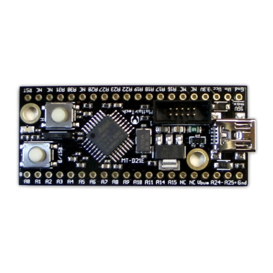
MT-D21E User Guide MTD21E Hardware MTD21E Hardware Top View / Pinout July 11, 2016 http://www.mattairtech.com/... -
Page 8: Main Header Pins (Power)
MT-D21E User Guide ============================= MattairTech MT-D21E (ATsamd21eXXa) ======================== Other Digital Analog Digital Other ========================================================================================= ------------------- Xin32 | A0 RST | Reset Xout32 | A1 2(ADC0) | A2 3(ADC1) | A3 A31 | 31 31(TCC11) 31(INT11) SWDIO* 4(INT4) 4(ADC4) | A4... -
Page 9: Main Header Pins (Signal)
PTC trip and hold currents. Main Header Pins (Signal) Description A0, A1 (Xin32, Xout32) These can be used for analog or digital functions. Alternatively, jumpers J16 and J17 can be set to route A0 and A1 to the 32.768KHz crystal. A2, A5, A6 These can be used for analog or digital functions. Pin A2 can be used as a DAC output. A3, A4 These can be used for analog or digital functions. Alternatively, jumpers J19 and/or J18 can be set to enable both a 100nF capacitor and a 1uF capacitor so that the pin can be used with an external voltage reference. A7 / Voltage Divider This can be used for analog or digital functions. Additionally, this pin can be connected to the voltage divider for measurement of Vin or Vbus by setting J3 and J12 appropriately. A8 A11 These can be used for analog or digital functions. A14, A15 (Xin, Xout) These can be used for digital functions. Pin A14 can be used with an external clock. Alternatively, jumpers J10 and J11 can be set to route A15 and A14 to the 16MHz crystal. A24, A25+ These can be used for digital functions. By default, these pins are also (USB D and D+) connected to pins D and D+ of the USB connector through jumpers J7 and J4. These header pins, along with the adjacent Vbus and Ground pins can be used for a panelmount USB connector. July 11, 2016 http://www.mattairtech.com/... - Page 10 User Guide A16, A17 (I2C) These can be used for digital functions. Additionally, jumpers J8 and J9 can be enabled, which will connect two 4.7Kohm pullup resistors for use with I2C. A18, A19, A22, A23 These can be used for digital functions. A27 / Button A This can be used for digital functions. By default, this pin is connected to Button A through jumper J13. This button is debounced using a 249ohm resistor and a 100nF capacitor. The pin is brought to ground when the button is pressed. The button is used for bootloader entry (optional) or can be for general purpose use. A28 / LED This can be used for digital functions. By default, this pin is connected to a blue LED through jumper J14 and a 499ohm resistor. The LED circuit should consume around 1mA. Drive the pin high to turn on the LED. A30 / SWD CLK This can be used for digital functions. Additionally, this pin is connected to the Cortex debug header where it is used as SWD CLK. A31 / Button B / SWD This can be used for digital functions. Additionally, the pin is routed to the Cortex debug header where it is used as SWD IO. Alternatively, this pin can be connected to Button B through jumper J15 (note that this button can also be used for RST). This button is debounced using a 249ohm resistor and a 100nF capacitor. The pin is brought to ground when the button is pressed. The button can be can be for general purpose use. RST connects to the reset pin of the microcontroller, to Button B through jumper J15 ( note that this button can also be for general purpose use; see A31 above), and to the Cortex debug header. A 10K pullup resistor is connected as well. These pins are not connected to anything. There are 7 pins marked NC. Cortex Debug Header This 10pin, 50mil header can be connected to an external programmer/debugger. July 11, 2016 http://www.mattairtech.com/...
-
Page 11: Solder Jumpers
J4: USB D+ / Pin A25 Microcontroller pins A24 and A25 are connected to header pins A24 and A25+. By default, these pins are also connected to pins D and D+ of the USB connector through jumpers J7 and J4. The header pins, along with the adjacent Vbus and Ground pins can be used for a panelmount USB connector. J5: Vcc – 3.3V This connects the 3.3V regulator output rail to Vcc. Open J5 if supplying a regulated voltage (3.6V or less) externally on the Vcc pin. J6: Vbus Power This routes Vbus to the regulator input circuitry. There are two schottky diodes, one for Vin and one for Vbus. They facilitate automatic power switching between these two sources. If only external power will be used (Vin), open J6. This will prevent Vbus power from being used when a USB cable is plugged in for communications. J7: USB D / Pin A24 See J4. J8: I2C pullup resistor Close J8 to connect pin A16 through a 4.7Kohm resistor to Vcc for use with I2C. J9: I2C pullup resistor Close J9 to connect pin A17 through a 4.7Kohm resistor to Vcc for use with I2C. J10: 16MHz crystal J10 and J11 determine whether microcontroller pins A15 and A14 connect to header pins A15 and A14 or to the 16MHz crystal. When the SAMBA bootloader is selection installed, the header pins are connected. If the MSD bootloader or no bootloader are installed, the alternate position is used by default(16MHz crystal connected). Note that the MSD bootloader does not use an external crystal, as it uses USB clock recovery (DFLL tuned using the USB SOF signal). J11: 16MHz crystal See J10. The image below shows connection to the header pins. selection J12: Voltage divider See J3. July 11, 2016 http://www.mattairtech.com/... - Page 12 J15: Button B function This jumper connects button B to either the RST pin, which is the default as shown in the image below, or to pin A31 for general purpose use. This button is debounced selection using a 249ohm resistor and a 100nF capacitor. The pin is brought to ground when the button is pressed. Note that pin A31 is also used by the Cortex debug header (SWD IO). The button can be completely disconnected by removing solder from all three pads. J16: 32.768KHz crystal J16 and J17 determine whether microcontroller pins A0 and A1 connect to header pins A0 and A1 or to the 32.768KHz crystal. When the SAMBA bootloader is selection installed, they are routed to the crystal. If the MSD bootloader or no bootloader is installed, they are routed to the header pins by default. Note that the MSD bootloader does not use an external crystal, as it uses USB clock recovery (DFLL tuned using the USB SOF signal). J17: 32.768KHz crystal See J16. selection J18: VREF capacitors When using pin A4 as VREF, close J18 to enable both a 100nF capacitor and a 1uF capacitor from A4 to ground. J19: VREF capacitors When using pin A3 as VREF, close J19 to enable both a 100nF capacitor and a 1uF capacitor from A3 to ground. Image note: The solder jumper configuration shows BOTH crystals disconnected. July 11, 2016 http://www.mattairtech.com/...
-
Page 13: Mattairtech Arduino Samd Core
MT-D21E User Guide MattairTech Arduino SAMD Core MattairTech Arduino SAMD Core Please visit https://github.com/mattairtech/ArduinoCoresamd for updated documentation and information on the new 1.6.7beta release with support for OS X and many updates. This is a fork from arduino/ArduinoCoresamd on GitHub. This will be used to maintain Arduino support for SAMD boards including the MattairTech MTD21E and the MTD11 (see https://www.mattairtech.com/). It primarily adds support for new devices as well as a more flexible pin configuration / mapping system. It also adds some size optimizations, including the ability to select any combination of CDC, HID, or UART through the menu (~7.5KB for blink sketch with CDC+HID+UART, ~2.5KB without USB or UART). This core is intended to be installed using Boards Manager (see below). To update from a previous version, click on MattairTech SAMD Boards in Boards Manager, then click Update. What's New (1.6.6-mt1, November 24, 2015) New documentation section 'Special Notes'. Please read! ● Updated ASCII pinouts to be more readable and less ambiguous. ● Updated the Signed driver for Windows (extras directory). ● adds CDC/MIDI/HID, CDC/MSD/HID, and CDC/MSD/MIDI/HID composite USB devices. Of the above, currently only CDC/MIDI/HID is usable (see MIDIUSB library). Merged in changes from upstream past SAMD CORE 1.6.2 release ● Added SPI.transfer16(..) method Bugfix: added missing Serial.begin(baud, config) method. Thanks @tuxedo0801 the pin mode is changed to INPUT mode, arduino/ArduinoCoresamd#28 ... -
Page 14: Summary
16 KB (4KB used by USB SAM Flash Memory 64 KB (D21E16A) / 32 KB (D21E15A) BA bootloader) 32 KB (D21E18A) / 16 KB (D21E17A) / 8 SRAM 4 KB KB (D21E16A) / 4 KB (D21E15A) None (emulation may be available in the None (emulation may be available EEPROM future) in the future) Digital Pins Analog Input Pins 10, 12bit ADC channels 10, 12bit ADC channels Analog Output Pins 1, 10bit DAC 1, 10bit DAC PWM Output Pins External Interrupts 15 (1 NMI) 9 (1 NMI) Device and Host (CDC and HID) Device and Host (CDC and HID) UART (Serial) I2C (TWI) 3.3V (Do not connect voltages higher than 3.3V (Do not connect voltages Operating Voltage 3.3V!) higher than 3.3V!) DC Current per I/O 7 mA 7 mA July 11, 2016 http://www.mattairtech.com/... -
Page 15: Special Notes
MT-D21E User Guide Special Notes Boards Manager must be opened twice to see some updates ● Errors when compiling, uploading, or burning the bootloader ● Be sure to install the Arduino samd core before installing the MattairTech samd core. If you have problems upgrading the IDE to 1.6.6, you may need to uninstall both the Arduino and MattairTech cores, then reinstall in the proper order. Use Arduino core 1.6.2 or above. Tools>Communications menu ● Currently, the Tools>Communications menu must be used to select the communications configuration. This configuration must match the included libraries. For example, when including the HID and Keyboard libraries, you must select an option that includes HID (ie: CDC_HID_UART). This menu is currently needed to select the USB PID that matches the USB device configuration (needed for Windows). This may become automatic in a future release. Be sure that the Tools>Communications menu matches the sketch and ➢ libraries you are compiling. Different combinations of USB devices will result in different COM port ➢ assingments in Windows. Incude platform specific libraries ● You may need to manually include platform specific libraries such as SPI.h, Wire.h, and HID.h. Differences from Arduino in versioning ● The MattairTech ArduinoCoresamd version currently tracks the IDE version. In some cases, it may indicate the minimum IDE version. This is the case for both ... -
Page 16: Pin Configurations
MT-D21E User Guide Pin Configurations Most pins have multiple configurations available (even analog pins). For example, pin A10 on the MT D21E can be an analog input, a PWM output, Digital I/O, or the TX pin of 'Serial1'. These always reference the pin number printed on the board but without the 'A' (with the usable pins starting at 2). DO NOT connect voltages higher than 3.3V! SAMD21 (MT-D21E) ============================= MattairTech MT-D21E (ATsamd21eXXa) ======================== Other Digital Analog Digital Other ========================================================================================= ------------------- Xin32 | A0 RST | Reset Xout32 | A1 2(ADC0) | A2 3(ADC1) | A3 A31 | 31... -
Page 17: Pin Capabilities
● External Interrupts: 15 pins (MTD21E) or 9 pins (MTD11) can be configured with ● external interrupts. Available using the attachInterrupt() function. ● Serial: 2 pairs of pins (MTD21E) or 1 pair (MTD11) can be configured for TTL serial I/O. ● MTD21E: Serial1: pin 11 (RX) and pin 10 (TX). Serial2: pin 15 (RX) and pin 14 (TX). ● MTD11: Serial1: pin 31 (RX) and pin 30 (TX). ● SPI: 3 or 4 pins can be configured for SPI I/O (SPI). ● MTD21E: Pin 18 (MOSI), pin 19 (SCK), pin 22 (MISO), and optionally pin 23 (SS, not ● currently used). MTD11: Pin 10 (MOSI), pin 11 (SCK), pin 14 (MISO), and optionally pin 15 (SS, not ● currently used). SPI communication using the SPI library. ● Note that the SPI library will set SS as an output. ● On the MTD11, the button must be configured as reset (default) when using SPI. ● TWI (I2C): 2 pins can be configured for TWI I/O (Wire). ● MTD21E: Pin 16 (SDA) and pin 17 (SCL). ● MTD11: Pin 22 (SDA) and pin 23 (SCL). ● TWI communication using the Wire library. ● LED: One pin can be configured to light the onboard LED (LED_BUILTIN). ● July 11, 2016 http://www.mattairtech.com/... -
Page 18: Mt-D21E And Mt-D11 Board Configuration
The upper end of the analog measurement range can be changed using the ● analogReference() function. Reset: Bring this line LOW to reset the microcontroller. ● MT-D21E and MT-D11 Board Configuration The 32.768KHz crystal is used by the Arduino core, so it MUST be connected via the ● solder jumpers. Note that the sketch may still run without the crystal attached, but the clock speed will ● be very inaccurate. The 16MHz crystal is not used. It should be disconnected via the solder jumpers. ● The I2C (TWI) pullup resistors should be enabled via the solder jumpers. ● The LED should be enabled via the solder jumper. ● Button A should be connected via the solder jumper. The debouncing capacitor should ● also be connected. Button B (MTD21E only) is connected to the Reset pin by default, but can be ● connected to pin 31 via the solder jumper. A reference voltage can be connected to AREF. In this case, the capacitors should be ● enabled via the solder jumper. On the MTD11, BTN is shared with SPI SS, so the button must be configured as reset ● (default) when using SPI. July 11, 2016 http://www.mattairtech.com/... -
Page 19: Serial Monitor
MT-D11 (Code + RAM) Blink (CDC + HID + UART) 7564 + 1524 7452 + 1424 Blink (CDC + UART) 6588 + 1496 6484 + 1396 Blink (CDC Only) 5248 + 1304 5192 + 1300 Blink (UART Only) 3828 + 336 3716 + 236 Blink (No USB or UART) 2472 + 144 2416 + 140 Datalogger (No USB or UART) 10340 + 948 10260 + 944 180 bytes of flash can be saved on the MTD11 by using PIN_MAP_COMPACT (see 'New ● PinDescription Table' below). Datalogger compiled without USB or UART support, but with SPI and SD (with FAT filesystem) ● support. Serial output was disabled. Note that USB CDC is required for autoreset into the bootloader to work (otherwise, manually ● press reset twice in quick succession). USB uses primarily 3 buffers totaling 1024 bytes. The UART uses a 96 byte buffer. The ● banzai() function (used for autoreset) resides in RAM and uses 72 bytes. Any combination of CDC, HID, or UART can be used (or no combination), ● by using the Tools>Communication menu. July 11, 2016 http://www.mattairtech.com/... -
Page 20: Detailed Memory Usage Output After Compilation
MT-D21E User Guide Detailed Memory Usage Output After Compilation The flash used message at the end of compilation is not correct. The number shown represents the .text segment only. However, Flash usage = .text + .data segments (RAM usage = .data + .bss segments). In this release, two programs are run at the end of compilation to provide more detailed memory usage. To enable this output, go to File >Preferences and beside "Show verbose output during:", check "compilation". Just above the normal flash usage message, is the output from the size utility. However, this output is also incorrect, as it shows .text+.data in the .text field, but 0 in the .data field. However, the .text field does show the total flash used. The .data field can be determined by subtracting the value from the normal flash usage message (.text) from the value in the .text field (.text+.data). The .bss field is correct. Above the size utility output is the output from the nm utility. The values on the left are in bytes. The letters stand for: T(t)=.text, D(d)=.data, B(b)=.bss, and everything else (ie: W) resides in flash (in most cases). July 11, 2016 http://www.mattairtech.com/... -
Page 21: Installation
MT-D21E User Guide Installation Driver Installation Windows There are currently four USB composite device combinations that include CDC as well as a CDC only device. Drivers are required for each of these five devices. The CDC only driver is required by the bootloader. The drivers are signed and support both 32 and 64 bit versions of Windows XP (SP3), Vista, 7, 8, and 10. 1. If you do not already have the SAMBA bootloader installed, see below. 2. Download https://www.mattairtech.com/software/MattairTech_CDC_Driver_Signed.zip and unzip into any folder. 3. Plug in the board while holding down button A to enter the bootloader. The LED should light. 4. Windows will detect the board. Point the installer to the folder from above to install the bootloader driver. 5. If you don't intend on using Arduino, you can skip the rest of this list. See Using Bossac Standalone below. 6. If you do not already have the test firmware installed, see Using Bossac Standalone below. 7. Press the reset button to run the test firmware (blink sketch with CDCHID). 8. Windows will detect the board. Point the installer to the folder from above to install the sketch driver. 9. Continue with SAMD Core Installation below. Linux 1. No driver installation is needed. 2. On some distros, you may need to add your user to the same group as the port (ie: dialout) ... -
Page 22: Samd Core Installation
4. No driver installation is needed. You may get a dialog box asking if you wish to open the “Network Preferences”: Click the "Network Preferences..." button, then click "Apply". ● The board will show up as “Not Configured”, but it will work fine. ● 5. Continue with SAMD Core Installation below. SAMD Core Installation To update from a previous version, click on MattairTech SAMD Boards in Boards Manager, then click Update. Boards Manager may require opening twice (with possibly a delay in between) to see some updates. 1. The MattairTech SAMD Core requires Arduino 1.6.6+ (1.6.5mtX required IDE 1.6.5). 2. In the Arduino IDE, click File>Preferences. 3. Click the button next to Additional Boards Manager URLs. 4. Add https://www.mattairtech.com/software/arduino/package_MattairTech_index.json. 5. Save preferences, then open the Boards Manager. 6. Install the Arduino SAMD Boards package. Use version 1.6.2 or higher with 1.6.6mtX. 7. Install the MattairTech SAMD Boards package (1.6.6mtX). 8. Close Boards Manager, then click Tools>Board>MattairTech MTD21E (or MTD11). 9. Select the processor with the now visible Tools>Processor menu. 10.If you do not already have the bootloader or blink sketch installed, see SAMBA USB CDC Bootloader below. 11.Plug in the board. The blink sketch should be running. 12.Click Tools>Port and choose the COM port. 13.You can now upload your own sketch. ... - Page 23 (in the pinDescription table) per TC channel. See WVariant.h for valid entries. The tone library uses TC5 (MT-D21E) or TC2 (MT-D11). ADCChannelNumber This is the ADC channel (if any) assigned to the pin. See WVariant.h for valid entries. July 11, 2016 http://www.mattairtech.com/...
-
Page 24: Possible Future Additions
● TFT LCD Motor controller ➢ IR decoder ➢ I2S DAC/AMP and I2S MEMS microphone ➢ Battery management IC ➢ XBee/Xbee Pro devices ➢ RS485 ➢ Several I2C (Wire) sensor devices: ● Accelerometer/gyro/magnetometer ➢ Barometer/altimeter ➢ Humidity/temperature ➢ Light/color sensor ➢ ChangeLog 1.6.6mt1: ● See 'What's New' above. ➢ 1.6.5mt2: ● Added support for the MTD11 (ATSAMD11D14AM). ➢ Reduced code size (see 'Code Size and RAM Usage' below). ➢ Any combination of CDC, HID, or UART can be used (or no combination), by ➢ July 11, 2016 http://www.mattairtech.com/... - Page 25 MT-D21E User Guide using the Tools>Communication menu. Note that switching between CDC and CDC+HID will require reselecting the ➢ COM port. More detailed memory usage at end of compilation (see below). ➢ Merged in upstream updates. Fixed Wire interrupt. ➢ Tested all ADC, DAC, external interrupts, PWM outputs, serial, SPI, and Wire ➢ instances/pins. 1.6.5mt1: ● Initial release ➢ July 11, 2016 http://www.mattairtech.com/...
-
Page 26: Samba Usb Cdc Bootloader (Arduino Compatible)
MT-D21E User Guide SAMBA USB CDC Bootloader (Arduino Compatible) SAMBA USB CDC Bootloader (Arduino Compatible) The SAMBA bootloader has both a CDC USB interface, and a UART interface (MTD21E: TX: pin 10, RX: pin 11). It is compatible with the Arduino IDE (Zero compatible), or it can be used with the Bossac tool standalone. Under Arduino, autoreset is supported (automatically runs the bootloader while the sketch is running) as well as automatic return from reset. The SAMBA bootloader described here adds to the Arduino version, which in turn is based on the bootloader from Atmel. The Arduino version added several features, including three new commands (Arduino Extended Capabilities) that increase upload speed. The bootloader normally requires 8 KB FLASH, however, a 4 KB version can be used for the D11 chips. Bossac is a command line utility for uploading firmware to SAMBA bootloaders. It runs on Windows. Linux, and OS X. It is used by Arduino to upload firmware to SAM and SAMD boards. The version Bossac described here adds to the Arduino version (https://github.com/shumatech/BOSSA, Arduino branch), which in turn is a fork from the original Bossa (http://www.shumatech.com/web/products/bossa). It adds support for more SAMD chips (both D21 and D11). Note that only the Arduino or Mattairtech versions of bossac are currently supported for SAMD chips. Neither the stock bossac (or Bossa) nor the Atmel SAMBA upload tool will work. Arduino Extended Capabilities: X: Erase the flash memory starting from ADDR to the end of flash. ● Y: Write the content of a buffer in SRAM into flash memory. ● Z: Calculate the CRC for a given area of memory. ● The bootloader can be started by: Tapping reset twice in quick succession (BOOT_DOUBLE_TAP). ● Holding down button A (BOOT_LOAD_PIN) while powering up. ● Clicking 'Upload Sketch' in the Arduino IDE, which will automatically start the bootloader. ● If the application (sketch) area is blank, the bootloader will run. ● Otherwise, it jumps to application and starts execution from there. The LED will light during bootloader execution. Note that the 4KB bootloader does not support the Arduino Extended ... -
Page 27: Bootloader Firmware Installation
User Guide any reason, the erase procedure will likely fail. 3. The board is reset. The bootloader (which always runs first) detects the blank flah row, so bootloader operation resumes. 4. Opening and closing the port at a baud rate other than 1200bps will not erase or reset the SAMD. Bootloader Firmware Installation Bootloader Installation Using the Arduino IDE 1. If you do not already have the MattairTech SAMD core installed, see SAMD Core Installation above. 2. Plug an Atmel ICE into USB, then connect it to the powered SAMD board. A green LED should light on the Atmel ICE. 3. Click Tools>Programmer>Atmel ICE. 4. Click Tools>Board>MattairTech MTD21E (or MTD11). 5. Click Tools>Burn Bootloader. Ignore any messages about not supporting shutdown or reset. 6. Continue with driver installation above. Bootloader Installation Using Another Tool (ie: Atmel Studio, openocd) Download the bootloader from https://www.mattairtech.com/software/arduino/SAMBA... -
Page 28: Using Bossac Standalone
MT-D21E User Guide Using Bossac Standalone When using Bossac standalone, you will need to ensure that your application starts at 0x00002000 for 8 KB bootloaders, and 0x00001000 for 4 KB bootloaders. This is because the bootloader resides at 0x00000000. This can be accomplished by passing the following flag to the linker (typically LDFLAGS in your makefile; adjust for your bootloader size): Wl,sectionstart=.text=0x2000 You may also use a linker script. See the MattairTech SAMD package for examples. Be sure to generate and use a binary file. Many makefiles are set up to generate an elf, hex, and bin already. Download Bossac from: https://www.mattairtech.com/software/arduino/bossac1.5arduinomattairtech1mingw32.zip ● (Windows 32 bit and 64 bit) https://www.mattairtech.com/software/arduino/bossac1.5arduinomattairtech1x86_64linux ● gnu.tar.bz2 (Linux 64 bit) https://www.mattairtech.com/software/arduino/bossac1.5arduinomattairtech1i686linux ● gnu.tar.bz2 (Linux 32 bit) Use the bossac command from the Arduino SAMD package for OS X support. Only the 256 KB ● chip versions are supported As an example, bossac will be used to upload the test firmware (blink sketch): Download firmware from https://www.mattairtech.com/software/SAMBAbootloadertest firmware.zip and unzip. 2. If you have not already installed the bootloader driver, see Driver Installation above. 3. Be sure there is a binary that matches your chip. On the command line (change the binary to match yours): 4. On Linux port might be /dev/ttyACM0. If the device is not found, remove the port argument for autodetection. bossac.exe -d --port=COM5 -U true -i -e -w -v Blink_Demo_ATSAMD21E18A.bin -R 1. -
Page 29: Usb Mass Storage Bootloader
MT-D21E User Guide USB Mass Storage Bootloader USB Mass Storage Bootloader Source code and binaries available at https://github.com/mattairtech/SAMDMSDBootloader A USB Mass Storage Class device (MSC or MSD) bootloader can be optionally installed. This will allow programming of the FLASH without an external programmer. Additionally, no special software is required on the host computer. The bootloader occupies the first 16KB of FLASH, leaving the rest for the user firmware. The BOOTPROT fuse bits (2:0) are set 0x01, which will protect the first 16KB of FLASH from internal or external programming (from 0x00000000 to 0x00004000). Note that the MSD bootloader does not use an external crystal, as it uses USB clock recovery (DFLL tuned using the USB SOF signal). Special Requirements when Compiling Software Because the user firmware will begin executing at FLASH byte address 0x00004000, you must ● pass the following flag to the linker (typically LDFLAGS in your makefile): Wl,sectionstart=.text=0x4000 Be sure to generate a binary file. Most makefiles are set up to generate an elf, hex, and bin ● already. You will need the bin file. You will need to rename the binary file to FLASH.BIN. ● Entering the bootloader and programming the firmware Enter the bootloader by pressing button A while powering up the board from USB. Or, hold ● button A while pressing and releasing button B (if configured as RST). Button A must be connected to pin A27 via solder jumper J13 (this will already be soldered if you ordered the bootloader option). Note that when no user firmware is installed, the bootloader will not ... - Page 30 MT-D21E User Guide Be sure to unmount the volume before running your new firmware, so that any disk caches are ● flushed. To run your firmware, simply reset or cycle power without pressing button A. ● Technical notes: The startup portion of the bootloader will run prior to executing your firmware. ● This startup code will enable the button A pullup resistor, wait 8ms for the debouncing capacitor to charge, then test the state of the button. If it is not pressed, the user firmware will be executed as follows: The stack pointer location will be rebased to 0x00004000 ● The interrupt vector table will be rebased to (0x00004000 & ● SCB_VTOR_TBLOFF_Msk) A jump will be perfomed to the user firmware reset vector. ● July 11, 2016 http://www.mattairtech.com/...
-
Page 31: Schematic
MT-D21E User Guide Schematic Schematic July 11, 2016 http://www.mattairtech.com/... -
Page 32: Fuse And Lock Settings
With Mass Storage Bootloader The Mass Storage Bootloader was preinstalled with the following commands (ATSAMD21E17A shown): atprogram t atmelice i SWD d atsamd21e17a cl 500khz program c verify f c:\msd_bootloader_128_flash.hex atprogram t atmelice i SWD d atsamd21e17a cl 500khz write fs o 0x00804000 values f9 Neither the region lock bits or the security bit is set. The three BOOTPROT fuse bits (2:0) are set to 0x01 (16KB). The blink program (compiled with an offset of 0x00004000) was then installed using the Mass Storage Bootloader. Without Bootloader The Blink program was preinstalled with the following commands (ATSAMD21E17A shown): atprogram t atmelice i SWD d atsamd21e17a cl 500khz program c verify f c:\MT_D21E_Blink_128_no_offset_flash.hex Neither the region lock bits or the security bit is set. The fuses are left at default settings. Blink Demo Blink Demo With SAM-BA (CDC) Bootloader The blink sketch comes preinstalled using the Arduino IDE. With MSD Bootloader or Without Bootloader A demo program comes preinstalled. It simply blinks the LED at 1Hz using an internal clock source. The hex files can be found on the MTD21E product page at https://www.mattairtech.com/. The blink demo was compiled using the Atmel Standalone Toolchain for Linux. It makes use of Atmel Software Framework (ASF) so it is rather large for a blink program. I can send the source upon request. I will post source if I ever recompile a simpler version that does not depend on ASF. July 11, 2016 http://www.mattairtech.com/... -
Page 33: Troubleshooting / Faq
On October 6, 2014, the old PTC fuse was replaced with a 180mA hold (400mA trip) 16V PTC ● fuse. Prior to November 16, 2014, the 16MHz crystal (18pF) was 20C 70C and the capacitors ● were 27pF. The new crystal (12pF) is 40C – 85C and the new capacitors are 13pF. Prior to January 31, 2016, there was a documentation error regarding J16 and J17, the solder ● jumpers associated with the 32.768KHz crystal. The image of the PCB bottom shows BOTH crystals disconnected (pins routed to the main headers). The text incorrectly indicated that J16 and J17 were set such that the 32.768KHz crystal was connected. I wrote the text with the intent to use an image with the 32.768KHz connected (SAMBA bootloader configuration), but I used the wrong image. Note that if the 32.768KHz crystal is disconnected, the crystal oscillator circuitry may still run at around 32KHz, but it will be unreliable and very inaccurate (USB may work intermittently). Support Information Support Information Please check the MattairTech website (http://www.MattairTech.com/) for firmware and software updates. Email me if you have any feature requests, suggestions, or if you have found a bug. If you need support, please contact me (email is best). You can also find support information at the MattairTech website. A support forum is planned. Support for Atmel ARM in general can be found at http://www.at91.com/. Justin Mattair MattairTech LLC PO Box 1079 Heppner, OR 97836 USA 541-626-1531 justin@mattair.net http://www.mattairtech.com/ July 11, 2016 http://www.mattairtech.com/... -
Page 34: Legal
Legal Legal Copyright / Licenses Arduino core files: This core has been developed by Arduino LLC in collaboration with Atmel. This fork developed by Justin Mattair of MattairTech LLC. Copyright (c) 2015 Arduino LLC. All right reserved. This library is free software; you can redistribute it and/or modify it under the terms of the GNU Lesser General Public License as published by the Free Software Foundation; either version 2.1 of the License, or (at your option) any later version. - Page 35 The author disclaims all warranties with regard to this software, including all implied warranties of merchantability July 11, 2016 http://www.mattairtech.com/...
- Page 36 * MERCHANTABILITY AND FITNESS FOR A PARTICULAR PURPOSE APPLY TO THIS SOFTWARE. * ARM SHALL NOT, IN ANY CIRCUMSTANCES, BE LIABLE FOR SPECIAL, INCIDENTAL, OR * CONSEQUENTIAL DAMAGES, FOR ANY REASON WHATSOEVER. ATSAMD21E Features (page 5) taken from Atmel datasheet. July 11, 2016 http://www.mattairtech.com/...
- Page 37 Further, the user indemnifies MattairTech LLC from all claims arising from the handling or use of the goods. Due to the open construction of the product, it is the user's responsibility to take any and all appropriate precautions with regard to electrostatic discharge and any other technical or legal concerns.
-
Page 38: Appendix A: Precautions
(ie: benchtop power supply leads). Inrush current is normally controlled by the PTC fuse, which has a small series resistance. CAUTION The MT-D21E contains static sensitive components. Use the usual ESD procedures when handling. July 11, 2016 http://www.mattairtech.com/... -
Page 39: Appendix B: Other Mattairtech Products
MT-D21E User Guide Appendix B: Other MattairTech Products Appendix B: Other MattairTech Products MTD11 USB ARM Cortex M0+ board ● ATSAMD11D14AM (24pin) ● 16KB FLASH, 4KB SRAM ● Onboard 3.3V, 250mA LDO regulator (2uA quiescent) ● 16MHz and 32.768KHz crystals ● USB connector (power by USB or external up to 16V) ● Blue LED, 10pin Cortex header, button, I2C pullups ● USB CDC Bootloader (no programmer required) ● Arduino 1.6.5+ support (core and bootloader) ● MTDBX3 USB AVR XMEGA board ● XMEGA A3U, A3BU, C3, and D3 (64pin) ● 32KB 384KB FLASH, 4KB – 32KB SRAM ● 3.3V 250mA regulator (2uA quiescent current) ● Optional 5V 500mA regulator (23uA quiescent current) ● Optional autodirection sensing level shifter ● 16MHz and 32.768KHz crystals, optional coin cell holder ● LED, boot jumper, PDI header, button, TWI pullups ● USB DFU bootloader preinstalled (except D variant) ●...
Need help?
Do you have a question about the MT-D21E and is the answer not in the manual?
Questions and answers