Table of Contents
Advertisement
Quick Links
Advertisement
Table of Contents

Related Manuals for MattairTech MT-DB-U1


Summary of Contents for MattairTech MT-DB-U1
- Page 1 Manual MTDBU1 December 30, 2015 http://www.mattairtech.com/...
-
Page 2: Table Of Contents
Externally Powered – 3.0V to 3.6V....................13 USB Shield............................13 Arduino Compatibility (IDE 1.6.7)................14 What's New............................. 14 Summary............................14 Special Notes..........................15 Pin Configurations........................... 15 MTDBU6 (AT90USB64/AT90USB128)..................16 MTDBU4 (ATmega32U4)......................17 MTDBU1/MTDBU2 (AT90USB162/ATmega32U2)..............17 Pin Capabilities..........................18 Using Arduino with MattairTech USB boards..................19 Serial Monitor..........................19 Updated Tone.cpp........................... 19 Detailed Memory Usage Output After Compilation................20 USB Technical Notes........................20 Installation............................21 Driver Installation..........................21 Windows............................21 Linux............................... 22 OS X............................... 22 AVR Core Installation........................22 Uploading the First Sketch......................23 USB CDC Bootloader (Arduino compatible)..................23... - Page 3 MT-DB-U1 Manual Possible Future Additions........................ 24 ChangeLog............................. 24 License and credits......................... 25 CDC Bootloader (Arduino/AVRDUDE)..............26 CDC Serial Driver..........................26 CDC Bootloader..........................26 DFU Bootloader (FLIP/dfuprogrammer)..............28 FLIP..........................29 dfuprogrammer..........................31 Running Demo Program....................32 Schematic........................33 Troubleshooting / FAQ....................34 Support Information....................34 Acknowledgments......................34 Legal..........................35 Appendix A: Precautions...................36 Appendix B: Other MattairTech Products..............37 December 30, 2015 http://www.mattairtech.com/...
-
Page 4: Overview
● 2 timers with 5 PWM channels ● Arduino compatib le (now supports IDE 1.6.7 and boards manager) ● CDC (Arduino/AVRDUDE) or DFU (FLIP) bootloader preinstalled ● ISP header pads (program chip using external programmer) ● 16MHz crystal ● Green Status LED ● 3 RC PWM filters on each output compare pin of 16bit timer 1 (can be disconnected) ● Reset button ● Bootloader selection jumper ● Mini USB connector ● Can be powered via USB at 5V (Vbus) or 3.3V (AT90usb162 internal regulator) ● Can be powered externally at 3V to 3.6V or 4V to 5.5V ● All programmable IO pins routed to headers (including those used by onboard hardware) ● USB pins routed to header pins (for panelmount USB connector) ● Highquality PCB with goldplated finish and red soldermask ● DIL32 board, standard 0.1" pin spacing. Can be mounted on a breadboard ● Measures approx. 1.7” x 0.8” (42mm x 20mm) and 0.062” (1.6mm) thick. ● December 30, 2015 http://www.mattairtech.com/... -
Page 5: At90Usb162 Features
USB 2.0 Fullspeed Device with Interrupt on Transfer Completion ● Complies fully with Universal Serial Bus Specification REV 2.0 48 MHz PLL for Fullspeed Bus Operation: 12 Mbit/s data rate Fully independant 176 bytes USB DPRAM for endpoint memory Endpoint 0 for Control Transfers: from 8 up to 64bytes 4 Programmable Endpoints: IN or Out Directions Bulk, Interrupt and IsochronousTransfers Programmable maximum packet size from 8 to 64 bytes Programmable single or double buffer Suspend/Resume Interrupts Microcontroller reset on USB Bus Reset without detach USB Bus Disconnection on Microcontroller Request Peripheral Features ● One 8bit Timer/Counters with Separate Prescaler and Compare (two 8bit PWM channels) One 16bit Timer/Counter with Prescaler, Compare and Capture (three 8bit PWM channels) USART with SPI master mode and hardware flow control (RTS/CTS) Master/Slave SPI Serial Interface Programmable Watchdog Timer with Separate Onchip Oscillator Onchip Analog Comparator Interrupt and Wakeup on Pin Change On Chip Debug Interface (debugWIRE) ● Special Microcontroller Features ● PowerOn Reset and Programmable Brownout Detection Internal Calibrated Oscillator External and Internal Interrupt Sources 5 Sleep Modes: Idle, Powersave, Powerdown, Stby., and Ext. Stby. I/O and Packages ● 22 Programmable I/O Lines December 30, 2015 http://www.mattairtech.com/... - Page 6 MT-DB-U1 Manual QFN32 (5x5mm) / TQFP32 packages Operating Voltages ● 2.7 – 5.5V Operating temperature ● Industrial (40 C to +85 C) Maximum Frequency ● 8 MHz at 2.7V Industrial range 16 MHz at 4.5V Industrial range December 30, 2015 http://www.mattairtech.com/...
-
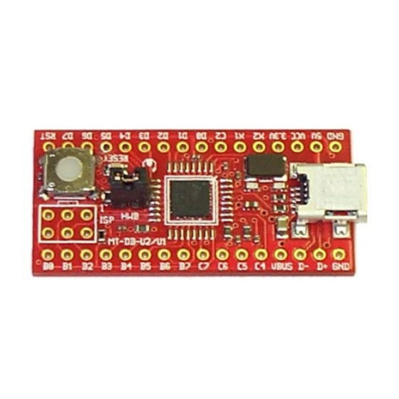
Page 7: Mtdbu1 Hardware
MT-DB-U1 Manual MTDBU1 Hardware MTDBU1 Hardware Layout / Header Pins December 30, 2015 http://www.mattairtech.com/... -
Page 8: Solder Jumpers
MT-DB-U1 Manual Solder Jumpers December 30, 2015 http://www.mattairtech.com/... -
Page 9: Pin Descriptions
X2 (C0) This pin can be connected to the XTAL2 pin of the microcontroller using jumper J7. This is useful if pin C0 is used as GPIO (if external clock is used). This pin is disconnected by default (onboard crystal is used). This pin can be connected to the XTAL1 pin of the microcontroller using jumper J7. This is useful if an external clock is used. This is also useful for HV programming or recovery from incorrectly set fuses. This pin is disconnected by default (onboard crystal is used). GPIO pin (Port C) Consult datasheet for functionality. D0 D7 GPIO pins (Port D) Consult datasheet for functionality. D0 / LED The green status LED is connected to this pin when solder jumper J2 is set. The LED is connected to ground through a 240 ohm resistor. The user application is free to use this LED. Drive the pin high to turn on the LED. D7 / HWB This pin is connected to the bootloader jumper (HWB). The jumper is connected to ground through a 240 ohm resistor. The pin is sampled after all reset sources, including powerup. If the pin is low (HWB jumper installed), then the bootloader is run. If the pin is high (HWB jumper removed), then the user application is run. This pin functions as a normal GPIO pin at all other times. The 240 ohm resistor provides shortcircuit protection in case the pin is used as an output and the jumper is installed. Connects to reset pin of microcontroller as well as the reset button. A 10K pullup resistor and 100nF capacitor are connected to this pin. If jumper J1 is set to ISP In, then RST is also connected to pin 5 of the ISP header. B0 B6 GPIO pins (Port B) Consult datasheet for functionality. PWM filter C output (OC.1C) or pin B7, depending on jumper configuration. C4, C7 GPIO pins (Port C) Consult datasheet for functionality. PWM filter B output (OC.1B) or pin C5, depending on jumper configuration. PWM filter A output (OC.1A) or pin C6, depending on jumper configuration. December 30, 2015 http://www.mattairtech.com/... -
Page 10: Pwm Filters
The filters consist of a 1K resistor and 100nF capacitor. The cutoff frequency is: =1/2 RC =1/2 1K∗100nF=1/2 0.0001=1600Hz This is a firstorder lowpass filter that can output levels from 0V to Vcc. All three filter inputs are connected to the 16bit timer 1 output compare pins ( OC.1A, OC.1B, and OC.1C). The filter inputs are always connected to the microcontroller. Therefore, if the solder jumpers are configured to connect the microcontroller pins directly to the header pins, there will be some loading on the pin (1K resistor in series with a 100nF capacitor to ground). Clock Source By default, a 16 MHz crystal is installed and connected to the XTAL pins of the AT90usb162. This 16 Mhz clock must be divided by 2 in software if the Vcc voltage is less than 4.5V. If an external clock is is used, solder jumper J6 can be switched to connect the microcontroller pin directly to header pin rather than the onboard crystal. An external clock signal can then be applied to pin X1 (XTAL1). This will also free up microcontroller pin C0 (XTAL2), which can be configured in the microcontroller as a GPIO pin and routed to header pin X2 by switching solder jumper J7. HWB Jumper / RESET button / LED The HWB Jumper is used to select either the bootloader or user application. The pin is sampled after reset or powerup. Note that the hardware HWB function of the AT90usb162 is disabled. That is, the HWBE fuse is disabled. The bootloader startup code is always run after reset or powerup (BOOTRST fuse is set). The code samples the state of the HWB pin. If the pin is low, the bootloader continues to run. If the pin is high, the user application is run. The green LED will pulse on and off using a continuously changing PWM period when the DFU bootloader is running. If the preinstalled demo program is running, it will be lit when USB is connected. Otherwise, the state of the LED is controlled by the user application. The bootloader always runs at 8 MHz, which is compatible with lower voltages.The user may set the cpu speed to 16MHz in software, if running at 5V. December 30, 2015 http://www.mattairtech.com/... -
Page 11: Isp Header
MT-DB-U1 Manual Jumper Mode Driver User Program CDC (COM port) (optional) Bootloader Program CDC Serial/DFU Bootloader It is not necessary to remove and replace the jumper when switching between the bootloader and the user application. The jumper can be left on. After FLASH programming, the CDC bootloader will automatically jump to the application. If using the DFU bootloader, then you can command FLIP or dfuprogrammer to jump to the application. Then, when running the application, the reset button can be pressed to reenter the bootloader. This is useful when writing and debugging firmware. When the firmware is complete, the jumper can be removed so that future resets will always run the application. The pins associated with the LED, jumper, and reset button are all routed to header pins. The LED can be disconnected by unsoldering jumper J2. The jumper is connected to pin D7 on one side and to ground through a 240 ohm resistor on the other side. There is a 10K pullup on the reset line. ISP Header The ISP header is configured by default to allow ISP programming using an external programmer. That is, RESET is routed to pin 5. Pin 1 is marked on the board (it is the pin closest to the chip). The ISP header can be reconfigured so that pin PB0 (SS) is connected to pin 5 rather than RESET. This can be done by switching solder jumper J1. This allows the MTDBU1 to be used as an AVRISPmkII programmer itself, using Dean Camera's AVRISPmkII software available at http://www.fourwalledcubicle.com/. A precompiled hex file will be made available at http://www.mattairtech.com/ on the MTDBU1 product page. Note that when using the ISP header in this way, Vcc and ground are output to the target board. Therefore, the target board should not be powered itself. You should also verify that it is safe to power the target board through the ISP connector. Another use for the ISP header configured with SS on pin 5 is to make use of SPI, either as a master or slave. SPI can also be used on the normal DIL headers. When using the ISP header, you may need to remove the HWB jumper to allow the ISP connector to fit. December 30, 2015 http://www.mattairtech.com/... -
Page 12: Power Configuration
Do not change any jumpers while the unit is powered. When using the microcontrollers internal regulator to power itself, be sure not to exceed the regulator maximum current output. USB Bus Powered 5V By default, the MTDBU1 is configured for 5V from the USB connector (Vbus). In this configuration, solder jumper J8 is set such that Vcc and UVcc are connected to Vbus (5V). The AVR internal 3.3V regulator must be enabled (default setting). This will supply 3.3V to the USB pads and 3.3V header pin. USB Bus Powered – 3.3V The internal 3.3V regulator can be used to supply the AVR itself with 3.3V. In this configuration, solder jumper J8 is set such that Vcc is connected to 3.3V and UVcc is connected to Vbus (5V). The AVR internal 3.3V regulator must be enabled (default setting). This will supply 3.3V to the AVR itself, December 30, 2015 http://www.mattairtech.com/... -
Page 13: Externally Powered - 4.0V To 5.5V
MT-DB-U1 Manual the USB pads, and the 3.3V header pin. Take care not to exceed the datasheet maximum current output of the internal regulator. Note that at 3.3V, the AVR should be set to run at 8MHz or less. This can be done in software using the prescaler. Externally Powered – 4.0V to 5.5V In this configuration, solder jumper J8 is set such that UVcc is connected to Vcc. Vcc is then supplied externally with 4.0V to 5.5V on the Vcc header pin. The 5V pin still outputs 5V when the USB cable is plugged in. The AVR internal 3.3V regulator must be enabled (default setting). This will supply 3.3V to the USB pads and 3.3V header pin. Note that when using a voltage less than 4.5V, the AVR should be set to run at 8MHz or less. This can be done in software using the prescaler. Externally Powered – 3.0V to 3.6V In this configuration, solder jumper J8 is set such that both UVcc and 3.3V are connected to Vcc. Vcc is then supplied externally with 3.0V to 3.6V on the Vcc header pin. The internal 3.3V regulator must be disabled in software. Note that the regulator is always enabled after reset or powerup, and is on when the bootloader is running. It is the responsibility of the user application to disable the regulator. The 5V pin still outputs 5V when the USB cable is plugged in. In this configuration, the AVR should be set to run at 8MHz or less. This can be done in software using the prescaler. USB Shield Jumper J9 can be soldered to connect the USB shield to ground. The USB specification calls for the USB shield to be connected to ground on the host side only. However, it may be desired to ground this on the device side. An 0603 SMT component may be soldered on the solder jumper pads as well. December 30, 2015 http://www.mattairtech.com/... -
Page 14: Arduino Compatibility (Ide 1.6.7)
MT-DB-U1 Manual Arduino Compatibility (IDE 1.6.7) Arduino Compatibility (IDE 1.6.7) This is a fork of the Arduino AVR core from arduino/Arduino (hardware/arduino/avr/ directory) on GitHub. This will be used to maintain Arduino support for AVR boards including the MattairTech MT DBU1, MTDBU2, MTDBU4, and the MTDBU6 (see https://www.mattairtech.com/). This core is intended to be installed using Boards Manager (see below). To update from a previous version, click on MattairTech AVR Boards in Boards Manager, then click Update. What's New Initial release of the 1.6.x compatible AVR core. ● Any combination of CDC, HID, or UART can be used (or no combination), by using the Tools ● >Communication menu. Note that switching between CDC and CDC+HID will require reselecting the COM port. ● More detailed memory usage at end of compilation (see below). ● Merged in upstream updates. ● Summary Feature MT-DB-U6 MT-DB-U4 MT-DB-U2 MT-DB-U1 AT90USB64/AT90US ATmega32U4, 8 ATmega32U2, 8 AT90USB162, 8 Microcontroller B128, 8Bit AVR Bit AVR Bit AVR Bit AVR Clock Speed 16 MHz 16 MHz 16 MHz... -
Page 15: Special Notes
MTDBU4: 1 additional analog pin is available by disconnecting the LED (solder jumper on rev B ● and higher boards) MTDBU664/128: 2 additional digital, 2 additional PWM, or 2 additional INT pins available with ● RTC crystal removed. Note however, that the RTC crystal holes are smaller and closer together than the header pin holes. Special Notes Tools>Communications menu ● Currently, the Tools>Communications menu must be used to select the communications configuration. This configuration must match the included libraries. For example, when including the HID and Keyboard libraries, you must select an option that includes HID (ie: CDC_HID_UART). This menu is currently needed to select the USB PID that matches the USB device configuration (needed for Windows). This may become automatic in a future release. Include platform specific libraries ● You may need to manually include platform specific libraries such as SPI.h, Wire.h, and HID.h. EXCEPTION_FOR_57600 ● The MattairTech ArduinoCoreavr uses a more accurate baud rate for 57600 than the stock arduino. When using the USART to communicate with another Arduino, define EXCEPTION_FOR_57600. New interrupt mapping ● The MattairTech ArduinoCoreavr has changed interrupt pin mapping from the previous 1.0.5 release. The arduino pin number is now used with attachInterrupt() instead of the interrupt number. See 'Pin Configurations' below. Pin Configurations To determine the Arduino pin number, start at the upperleft corner of the board opposite of the USB connector. This is pin 0 (most boards have a 0 printed nearby). The numbering increases in a counter clockwise direction around the board. Many pins have multiple configurations available. For example, arduino pin 29 (AVR pin D0) on the MTDBU6 can be a PWM output (analogWrite), an external interrupt input, digital I/O, or the SCL pin of I2C. December 30, 2015 http://www.mattairtech.com/... -
Page 16: Mt-Db-U6 (At90Usb64/At90Usb128)
MT-DB-U1 Manual MT-DB-U6 (AT90USB64/AT90USB128) ================== MattairTech MT-DB-U6 (AT90USB64/AT90USB128) ========================== INT/Other Analog Digital Digital INT/Other Comm ========================================================================================= --------------------- | E0/L RST | | E1 E2/B| JUMPER | C0 | C1 | C2 | C3 6 (TC3C) | C4 O O *... -
Page 17: Mt-Db-U4 (Atmega32U4)
MT-DB-U1 Manual MT-DB-U4 (ATmega32U4) ========================= MattairTech MT-DB-U4 (ATmega32U4) ============================= INT/Other Analog Digital Digital Analog INT/other Comm ========================================================================================= ------------------- 0 (ADC11) | B4 RST | 1 (TC1A) 1 (ADC12) | B5 D7/L| 25 25 (ADC10) 25 (TC4D) 2 (TC1B) 2 (ADC13) -
Page 18: Pin Capabilities
● MTDBU4: Serial1: pin 20 (RX) and pin 21 (TX). ● MTDBU2, MTDBU1: Serial1: pin 15 (RX) and pin 16 (TX). ● SPI: 3 or 4 pins can be configured for SPI I/O (SPI). ● MTDBU6: Pin 21 (MOSI), pin 20 (SCK), pin 22 (MISO), and optionally pin 19 (SS, not ● currently used). MTDBU4: Pin 15 (MOSI), pin 14 (SCK), pin 16 (MISO), and optionally pin 13 (SS, not ● currently used). MTDBU2, MTDBU1: Pin 2 (MOSI), pin 1 (SCK), pin 3 (MISO), and optionally pin 0 ● (SS, not currently used). SPI communication using the SPI library. ● TWI (I2C): 2 pins can be configured for TWI I/O (Wire). ● MTDBU6: Pin 30 (SDA) and pin 29 (SCL). ● MTDBU4: Pin 19 (SDA) and pin 18 (SCL). ● MTDBU2, MTDBU1: TWI not present ● TWI communication using the Wire library. ● LED: One pin can be configured to light the onboard LED (LED_BUILTIN). ● Pin 0 (MTDBU6), pin 25 (MTDBU4), or pin 13 (MTDBU2, MTDBU1). ● Bring the pin HIGH to turn the LED on. ● AREF: One pin can be configured as an AREF analog input. ● December 30, 2015 http://www.mattairtech.com/... -
Page 19: Using Arduino With Mattairtech Usb Boards
MT-DB-U1 Manual The upper end of the analog measurement range can be changed using the ● analogReference() function. Reset: Bring this line LOW to reset the microcontroller. ● Using Arduino with MattairTech USB boards Because of the similarities with the Arduino Leonardo, please read http://arduino.cc/en/Guide/ArduinoLeonardo first. Within the Arduino IDE Tools menu, select the appropriate MattairTech board, Frequency/Voltage, Processor, Communications setting, and COM port. There are 2 Frequency/Voltage configurations for each board, 16MHz(5V) and 8MHz(3.3V). You may select 8MHz even if using 5V. When operating at 3.3V, you should select 8MHz. Operating at 16MHz at 3.3V is out of spec, but should work fine at room temperatures. Be sure to select the Communications setting that matches your sketch (by default, this is CDC_ONLY). This is important. Note that some example sketches indicate the use of pins using the naming convention D2, D3, etc. These are Arduino digital pins, not to be confused with port D pins. Most MattairTech USB AVR boards are printed with both port pin names as well as sequential numbers indicating the Arduino pin number. You may use the 'A' or 'D' prefixes, but they are simply aliased to the arduino pin number (ie: A2 = D2 = 2). There are several libraries included with Arduino. Some of these need simple changes to work with MattairTech boards. Usually, only pin mappings need to be changed. Serial Monitor To print to the Serial Monitor over USB, use 'Serial'. Serial points to SerialUSB (Serial1 is a UART). Unlike most Arduino boards (ie. Uno), USB AVR based boards do not automatically reset when the serial monitor is opened. To see what your sketch outputs to the serial monitor from the beginning, the sketch must wait for the SerialUSB port to open first. Add the following to setup(): while (!Serial) ; Remember that if the sketch needs to run without SerialUSB connected, another approach must be ... -
Page 20: Detailed Memory Usage Output After Compilation
#define USB_CDC_NOTIFICATION_EP_BANKS #define USB_CDC_DATA_EP_SIZE #define USB_CDC_DATA_EP_BANKS // These can optionally be used by PluggableUSB libraries #define USB_HID_EP_SIZE #define USB_HID_EP_BANKS #define USB_MIDI_EP_SIZE #define USB_MIDI_EP_BANKS #define USB_MSD_EP_SIZE #define USB_MSD_EP_BANKS AT90USBxx2: 176 bytes DPRAM, 8 64 byte endpoints, 1 (control) + 2 (one bank) + 2 (two banks) endpoints ATmegaxxU2: 176 bytes DPRAM, 8 64 byte endpoints, 1 (control) + 2 (one bank) + 2 (two banks) endpoints // These are used by the core December 30, 2015 http://www.mattairtech.com/... -
Page 21: Installation
#define USB_MSD_EP_BANKS Installation Driver Installation Windows Prior to core version 1.6.9mt1, sketches compiled with both CDC and HID USB code by default, thus requiring a CDC driver for the bootloader and a CDCHID driver for sketches. Now that PluggableUSB is supported, sketches compile with only CDC code by default. Thus, only one driver is needed. Since HID and MIDI are currently supported (and MSD potentially in the future), driver installation will be required for each different combination of USB devices. There are currently four USB composite device combinations that include CDC as well as a CDC only device. Each supported combination has a unique USB VID:PID pair, and these are listed in the .inf file. Once the first device is installed (the CDC only device), future installations might be automatic, otherwise, you may direct the installer to the same .inf file. The drivers are signed and support both 32 and 64 bit versions of Windows XP(SP3), Vista, 7, 8, and 10. 1. If you do not already have the CDC bootloader installed, see below. Download https://www.mattairtech.com/software/MattairTech_CDC_Driver_Signed.zip and unzip into any folder. 3. Plug in the board with the jumper installed. The LED should light. 4. Windows will detect the board. Point the installer to the folder from above to install the bootloader driver. 5. If you don't intend on using Arduino, you can skip the rest of this list. See Using AVRDUDE Standalone below. 6. If you do not already have the test firmware installed, see Using AVRDUDE Standalone below. 7. Press the reset button to run the test firmware (blink sketch). 8. Windows will detect the board. Point the installer to the above folder to install the sketch driver (if needed). 9. Continue with AVR Core Installation below. December 30, 2015 http://www.mattairtech.com/... -
Page 22: Linux
OS X UNTESTED 1. No driver installation is needed. 2. Plug in the board. You may get a dialog box asking if you wish to open the “Network Preferences”: Click the "Network Preferences..." button, then click "Apply". ● The board will show up as “Not Configured”, but it will work fine. ● 3. Continue with AVR Core Installation below. AVR Core Installation To update from a previous version, click on MattairTech AVR Boards in Boards Manager, then click Update. 1. The MattairTech AVR Core requires Arduino 1.6.7+. 2. In the Arduino IDE 1.6.7+, click File>Preferences. 3. Click the button next to Additional Boards Manager URLs. Add https://www.mattairtech.com/software/arduino/package_MattairTech_index.json. 5. Save preferences, then open the Boards Manager. 6. Install the MattairTech AVR Boards package. 7. Close Boards Manager, then select your board from Tools>Board. 8. Select the Frequency/Voltage with the now visible Tools>Frequency/Voltage menu. 9. Select the processor with the now visible Tools>Processor menu. 10.Select the communications option with the now visible Tools>Communications menu (must match sketch). 11.If you do not already have the bootloader or blink sketch installed, see USB CDC Bootloader below. ... -
Page 23: Uploading The First Sketch
#define ENABLE_LED_BOOT #define ENABLE_LED_APPLICATION #define DISABLE_JTAG_APPLICATION #define ENABLE_CLKDIV_1_APPLICATION #define ENABLE_BOOT_KEY #define ENABLE_RESET_AFTER_PROGRAMMING #define NO_LOCK_BYTE_WRITE_SUPPORT An alternate version with the above options undefined is available on the website named Bootloader_no_options.hex. Use it if the default options interfere with your application. For example, you may disconnect the LED and use the pin as an analog input. Bootloader Firmware Installation Using the Arduino IDE 1. If you do not already have the MattairTech AVR core installed, see AVR Core Installation above. 2. Plug a compatible programmer into a USB port, then connect it to the powered AVR board. 3. Select your programmer from Tools>Programmer. 4. Select your board from Tools>Board. 5. Click Tools>Burn Bootloader. Ignore any messages about not supporting shutdown or reset. 6. Continue with driver installation above. December 30, 2015 http://www.mattairtech.com/... -
Page 24: Using Avrdude Standalone
MT-DB-U1 Manual Using AVRDUDE Standalone AVRDUDE can be used standalone. You can use the version included with Arduino (in arduino 1.6.7/hardware/tools/avr/bin) or download a separate version from http://download.savannah.gnu.org/releases/avrdude/. As an example, AVRDUDE will be used to upload the test firmware (blink sketch): Download firmware from https://www.mattairtech.com/software/CDCbootloadertest firmware.zip and unzip. 2. If you have not already installed the bootloader driver, see Driver Installation above. 3. Be sure there is a hex file that matches your chip. On the command line (change the hex file to match yours): avrdude -p m32u4 -c avr109 -P usb -U flash:w:"blink.hex" 1. On linux, the P option should be something like /dev/ttyACM0. See http://www.nongnu.org/avrdude/usermanual/avrdude_4.html for details. 3. Press the reset button with the jumper off to load the sketch. 4. When using AVRDUDE standalone, the jumper must be installed before pressing reset to run the bootloader. Possible Future Additions Features for lower power consumption ● MSC (Mass Storage) USB Device Class ●... -
Page 25: License And Credits
130303, updates the Arduino core files and libraries to 1.0.4, updates the bootloaders, and adds support for the new MTDBU6. License and credits This core has been developed by Arduino LLC. This fork developed by Justin Mattair of MattairTech LLC. Copyright (c) 2015 Arduino LLC. All right reserved. This library is free software; you can redistribute it and/or modify it under the terms of the GNU Lesser General Public License as published by the Free Software Foundation;... -
Page 26: Cdc Bootloader (Arduino/Avrdude)
MT-DB-U1 Manual CDC Bootloader (Arduino/AVRDUDE) CDC Bootloader (Arduino/AVRDUDE) CDC Serial Driver The CDC Serial driver allows the board to appear as a COM port. The driver itself is included with Windows, but an .inf file is needed to configure it. Download the .inf file from https://www.mattairtech.com/software/MattairTech_CDC_Driver_Signed.zip . Note that Windows Vista 64bit, Windows 7 64bit and Windows 8 require the signed driver. You may need to rename the file so that it has the inf extension. Next, plug in the board with the jumper removed. Windows will then prompt you for the MattairTech CDC Serial driver. Point the installer to the directory where you downloaded the driver and install, ignoring any warnings. Once the driver is loaded, the device will appear as the MattairTech CDC Serial device using a COM port in the device manager. If you wish, doubleclick on the CDC Serial device entry in the device manager to configure the driver. Nothing on the port settings tab needs to be changed. We are using a virtual COM port so the settings are ignored. The baud rate will always be as fast as possible. On the advanced tab, you can adjust the FIFO buffer sizes. If you experience any buffering problems (ie: a delayed response to user input), then change both buffer sizes to 1. CDC Bootloader The CDC bootloader uses the AVR109 protocol, and can be used withing the Arduino environment, or directly with AVRDUDE. Version 130410 or above is required to support the auto reset feature (note that several boards that were shipped before 130626 still have the old bootloader). If using a terminal emulator, you must first disconnect before running the bootloader. The bootloader enters programming mode only if the jumper is installed, even when using Arduino autoreset. The one exception is when the FLASH is empty. Even with the jumper installed, programming mode will NOT be entered if the reset was from the watchdog timer. The one exception to this is when the boot key is enabled and the key matches. The key will match when the Arduino IDE autoresets the board to enter bootloader programming mode. The key is needed because the Arduino core part of the firmware, which listens for the IDE autoreset signal, uses a watchdog reset to enter the bootloader. This way, the user application can make use of the watchdog timer. The bootloader will jump to the user application at the end of FLASH programming. Other operations with AVRDUDE, like writing the EEPROM, will not trigger this. Just press reset to get back to the bootloader (as long as the jumper is installed). December 30, 2015 http://www.mattairtech.com/... - Page 27 #define DISABLE_JTAG_APPLICATION #define ENABLE_CLKDIV_1_APPLICATION #define ENABLE_BOOT_KEY #define ENABLE_RESET_AFTER_PROGRAMMING #define NO_LOCK_BYTE_WRITE_SUPPORT An alternate version with the above options undefined is available on the website named Bootloader_no_options.hex. Use it if the default options interfere with your application. For example, you may disconnect the LED and use the pin as an analog input. When using the autoreset feature of Arduino, the boards.txt file must currently list the bootloader directory as caterina (the bootloader used on the Leonardo). The actual bootloader is a modified version of the LUFA CDC bootloader by Dean Camera (lufalib.org). It resides in the mtdbxx folder (where xx corresponds to the board you have). So, if you wish to use the Arduino IDE to burn the bootloader, you must temporarily change the appropriate entry in the boards.txt file to point toward the actual bootloader directory. Change it back to caterina when finished to reenable autoreset. Example for Windows: avrdude -p m32u4 -c avr109 -P COM5 -U flash:w:"bitlashdemo_MT-DB-U4.hex" Example for Linux: avrdude -p m32u4 -c avr109 -P /dev/ttyACM0 -U flash:w:"bitlashdemo_MT-DB-U4.hex" Arduino environment: Be sure to select the COM port. Then upload your sketch with the Upload button. December 30, 2015 http://www.mattairtech.com/...
-
Page 28: Dfu Bootloader (Flip/Dfuprogrammer)
MT-DB-U1 Manual DFU Bootloader (FLIP/dfuprogrammer) DFU Bootloader (FLIP/dfuprogrammer) Installation FLIP is a graphical utility used to load firmware into the AT90usb162. FLIP includes the DFU bootloader driver. It supports Windows XP through Windows 7 (32 or 64 bit). Download FLIP 3.4.2 or higher from http://www.atmel.com/dyn/products/tools_card.asp?tool_id=3886 and install. Once FLIP is installed, the DFU bootloader drivers can be loaded. Install the HWB jumper and powerup the board (or press reset). This will enter the DFU bootloader. The LED should be pulsing. Windows will then prompt you for the AT90usb162 driver. By default, this is located in the Program Files/Atmel/Flip 3.4.2/usb directory. Point the installer to that directory and install. Once the driver is loaded, the device will appear as the AT90usb162 device under Atmel USB Devices in the device manager. December 30, 2015 http://www.mattairtech.com/... -
Page 29: Flip
MT-DB-U1 Manual FLIP FLIP Install the HWB jumper and powerup the board (or press reset). This will enter the DFU bootloader. The LED should be pulsing. Now launch the FLIP utility. When it has loaded, click on the chip icon and select the AT90usb162. December 30, 2015 http://www.mattairtech.com/... - Page 30 MT-DB-U1 Manual Next, click on the USB icon, select USB, then connect. The screen should now show information about the AT90usb162. Click on the File menu, and open the appropriate hex file. More information will appear about the program. Be sure that erase is checked. The firmware cannot be loaded unless the flash is erased first. Program must be checked. Verify should also be checked. Now click on the Run button in the lowerleft of the screen, and the firmware will be quickly loaded onto the AT90usb162. You may also program the EEPROM. If so, click on Select EEPROM at the bottom. Then, click on the File menu and open the appropriate eep file. You will have to change the file filter to allow you to see the eep file. Note that eep files are just hex files but with the eep extension instead of hex. More information will appear about the file when selected. Both Program and Verify should be checked. Click run to program the EEPROM. You can run your application without removing the jumper or pressing reset by unchecking the reset box and pressing the “Start Application” button (lower right). December 30, 2015 http://www.mattairtech.com/...
-
Page 31: Dfuprogrammer
MT-DB-U1 Manual dfuprogrammer dfuprogrammer is a command line utility used to program the AT90usb162 that runs under Linux. A DFU driver installation is not required. Download version 0.5.4 or higher from http://dfu programmer.sourceforge.net/ . The following commands can be used: dfuprogrammer AT90usb162 erase dfuprogrammer AT90usb162 flasheeprom YourHex.eep (if applicable) dfuprogrammer AT90usb162 flash YourHex.hex dfuprogrammer AT90usb162 start (to jump to application section without reset) December 30, 2015 http://www.mattairtech.com/... -
Page 32: Running Demo Program
MT-DB-U1 Manual Running Demo Program Running Demo Program The demo program makes use the use of the MTDBU1 as a CDC device (virtual COM port). This is one of the most common ways to connect to a PC over USB. It uses Dean Camera's open source LUFA USB library available at http://www.fourwalledcubicle.com/. The LUFA download includes many examples that can be easily compiled for the AT90USB162. See the CDC Bootloader section for details on installing the CDC Serial driver. The old demo requires an ANSI terminal to allow drawing of the menu system. If you see garbage on the terminal screen, click on the configuration icon and change the emulation to ANSI (or ANSIW). After connecting, a message that reads “Press any Key” is printed periodically. If you do not see this message, just press any key to continue. December 30, 2015 http://www.mattairtech.com/... -
Page 33: Schematic
MT-DB-U1 Manual Schematic Schematic December 30, 2015 http://www.mattairtech.com/... -
Page 34: Troubleshooting / Faq
MT-DB-U1 Manual Troubleshooting / FAQ Troubleshooting / FAQ Nothing yet Support Information Support Information Please check the MattairTech website (http://www.MattairTech.com/) for firmware and software updates. Email me if you have any feature requests, suggestions, or if you have found a bug. If you need support, please contact me (email is best). You can also find support information at the MattairTech website. A support forum is planned. Support for AVRs in general can be found at AVRfreaks (http://www.avrfreaks.net/). There, I monitor the forums section as the user physicist. Justin Mattair MattairTech LLC PO Box 1079 Heppner, OR 97836 USA 541-626-1531 justin@mattair.net http://www.mattairtech.com/ Acknowledgments Acknowledgments Thanks to Dean Camera (http://www.fourwalledcubicle.com/) for his excellent LUFA library and bootloaders. Thanks to the members of AVRfreaks (http://www.avrfreaks.net/) for their support. Finally, thanks to Atmel for creating a great product, the AVR microcontroller. December 30, 2015 http://www.mattairtech.com/... -
Page 35: Legal
Further, the user indemnifies MattairTech LLC from all claims arising from the handling or use of the goods. Due to the open construction of the product, it is the user's responsibility to take any and all appropriate precautions with regard to electrostatic discharge and any other technical or legal concerns. -
Page 36: Appendix A: Precautions
(programmed = 0), and that you are using an appropriate programming speed before attempting to change fuse settings. December 30, 2015 http://www.mattairtech.com/... -
Page 37: Appendix B: Other Mattairtech Products
MT-DB-U1 Manual Appendix B: Other MattairTech Products Appendix B: Other MattairTech Products ZeptoProg II AVRISP mkII Programmer ● AVRISPmkII compatible AVR Programmer ● Supports all AVRs with ISP, PDI, or TPI ● Optional 5V output via headers to target board, with ● standard jumper and PTC fuse 4channel Logic Analyzer ● Serial bridge / pattern generator / SPI interface ● GPIO / PWM / frequency input & output ● Atmel Studio / AVRDUDE support ● Target board voltage of 2V to 5.5V via levelshifted ● pins on two main headers MTDBU6 USB AVR development board ● AT90USB646 / AT90USB1286 USB AVR ● 64KB/128KB FLASH, 4KB/8KB SRAM ● 5V, 500mA LDO regulator (3V30V input) ● Auto power source selection IC (USB/External) ● 16MHz and 32.768KHz crystals ● Arduino compatible ● CDC or DFU bootloader ●...
Need help?
Do you have a question about the MT-DB-U1 and is the answer not in the manual?
Questions and answers