
Related Manuals for Global Fire Equipment ORION EX MINI-REP


Summary of Contents for Global Fire Equipment ORION EX MINI-REP
- Page 1 Manufacturers of Fire Detection Equipment ORION EX MINI-REP INSTALLATION MANUAL 1.0 - 06/2015 ORION EX MINI-REP EXTINGUISHING CONVENTIONAL REPEATER PANEL INSTALLATION MANUAL VERSION 1.0 - 06/2015 globalfire.pt...
-
Page 2: Important Safety Notes
INSTALLATION MANUAL 1.0 - 06/2015 OVERVIEW The ORION EX MINI-REP will provide remote control and system display status from multiple locations to an Orion based Conventional Fire Alarm system. Its reduced dimensions make it ideal for installation in reception areas or security booths where it would be impractical and unattractive to install a full size control panel. -
Page 3: Installation
Orion Ex Mini-Rep unit on a networked system. f) Connect Power Supply. Orion Ex Mini-Rep are supplied by an external 24V DC, normally from the control panel. Do not apply supply voltage until installation is complete. -
Page 4: Mechanical Details
INSTALLATION MANUAL 1.0 - 06/2015 MECHANICAL DETAILS 256 mm 75 mm Top Cable Entry Rear Cable Entry Orion Ex Mini-Rep Data Loop Interface PCB - Stand-offs Orion Ex Mini-Rep Back Box - Mounting Holes 246 mm Figure 1: ORION EX MINI-REP - Installation globalfire.pt... - Page 5 Manufacturers of Fire Detection Equipment ORION EX MINI-REP INSTALLATION MANUAL 1.0 - 06/2015 Connect Orion Ex Mini-Rep CON3 (Data Loop) to corresponding interface. +24 V DC Ground ( 0V ) Earth Figure 2: ORION EX MINI-REP - General Hardware and Connections Layout globalfire.pt...
- Page 6 Orion conventional panel. All other Orion Ex Mini-Rep’s will only be able to display system status. Maximum distance between Panel and last Orion Ex Mini-Rep should be 100 meters. Figure 3: ORION EX MINI-REP - RS-232 Data Loop Interface Connections globalfire.pt...
- Page 7 Interface CON3 should be connected to DATA connector (Cn3) placed on the underside of the Orion panel main board and to Data Loop connector (CON3) on Orion Ex Mini-Rep board. Figure 3: Orion Panel Multi - ORION EX MINI-REP - RS-485 interface connections.
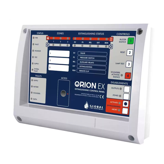
- Page 8 Manufacturers of Fire Detection Equipment ORION EX MINI-REP INSTALLATION MANUAL 1.0 - 06/2015 THE ORION EX MINI-REP SYSTEM STATUS INDICATORS AND CONTROL BUTTONS STATUS FIRE LED used to indicate any FIRE ALARM condition present on panel. FAULT LED used to indicate any FAULT condition present on panel.
- Page 9 Manufacturers of Fire Detection Equipment ORION EX MINI-REP INSTALLATION MANUAL 1.0 - 06/2015 FAULTS SUPPLY This LED will be ON whenever the Main Supply has been removed or has dropped below 20 Volts. BATTERY Indicates that there is low voltage level on the batteries or the battery charger circuit has failed.
-
Page 10: Technical Specifications
Manufacturers of Fire Detection Equipment ORION EX MINI-REP INSTALLATION MANUAL 1.0 - 06/2015 EXTINGUISHING CYCLE The extinguishing process can be controlled manually using the buttons available on the front display. The extinguishing cycle cn be initiated manually executing the following steps: a) In level 1, silence the internal buzzer using the INTERNAL BUZZER SILENCE button if there are any Fire or Fault conditions which have not been acknowledged. - Page 11 Manufacturers of Fire Detection Equipment ORION EX MINI-REP INSTALLATION MANUAL 1.0 - 06/2015 GLOBAL FIRE EQUIPMENT S.A. Sítio dos Barrabés, Armazém Nave Y, Caixa Postal 908-Z, 8150-016 São Brás de Alportel - PORTUGAL Tel: +351 289 896 560 • Sales: sales@globalfire.pt • Technical Support: techs@globalfire.pt • www.globalfire.pt...
Need help?
Do you have a question about the ORION EX MINI-REP and is the answer not in the manual?
Questions and answers