Table of Contents
Advertisement
Quick Links
1165/1165H/1165HS Wireless Commercial Smoke Detectors
Description
The Model 1165 Smoke Detector, 1165H Smoke/Heat Detector, and 1165HS Smoke/Heat Detector with Sounder are
photo electric, wireless detectors used with the 1100X Series Wireless Receivers.
Features
• Tamper switch sends a trouble signal to the control
panel when the detector is removed from the
mounting base.
• Optional integrated fixed 135°F temperature and
rate of rise heat detector trips an alarm based on
temperature detected.
Included Components
• One 1165 Smoke Detector with DMP wireless
transmitter installed
OR
• One 1165H Smoke/Heat Detector with DMP wireless
transmitter installed
OR
• One 1165HS Smoke/Heat Detector with Sounder
with DMP wireless transmitter installed
AND
• Two 3V lithium Panasonic CR123A (DMP part number CR123-FIRE) batteries
• Hardware pack
Programming the Transmitter in the Panel
Program the device as a zone in Zone Information during panel programming. At the Serial Number: prompt, enter
the eight-digit serial number. Set supervision time to 3. Continue to program the zone as directed in the panel
programming guide.
Note: When a receiver is installed, powered up, or the panel is reset, the supervision time for transmitters is reset.
If the receiver has been powered down for more than one hour, wireless transmitters may take up to an additional
hour to send a supervision message unless tripped, tampered, or powered up. This operation extends battery life for
transmitters. A missing message may display on the keypad until the transmitter sends a supervision message.
Transmitted Signal Outputs
The smoke detector provides the signals listed in the table:
Selecting the Proper Location (LED Survey Operation)
The 1165/1165H/1165HS Transmitter provides a survey capability to allow one person to confirm transmitter
communication with the receiver. The 1165/1165H/1165HS Transmitter PCB Red Survey LED turns on whenever data
is sent to the receiver then immediately turns off when the receiver acknowledgement is received. Pressing the test
button is a convenient way to send data to the receiver to confirm operation. The transmitter survey LED can be
seen around the test button location. When the transmitter does not receive an acknowledgement from the receiver
the LED remains on for about 8 seconds to let you know communication is not established. Communication is also
faulty when the LED blinks multiple times in quick succession. Relocate the transmitter or receiver until the LED
immediately turns off indicating the transmitter and receiver are communicating properly. Proper communication
between the transmitter and receiver is verified when for each press or release of the test button, the LED blinks
immediately on and immediately off. Repeat this test to confirm five separate consecutive LED blinks. Any indication
otherwise means proper communication has not been established.
INST ALLA TION SHEET
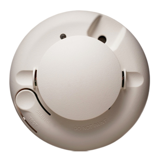
Optional Heat Sensor
Test Button
Signal
Keypad Display
Alarm
ALARM
Alarm restore
Low battery
LOBAT
LED
Figure 1: Smoke Detector Features
OK
Sounder Vent
Optional Heat Sensor
Advertisement
Table of Contents

Related Manuals for DMP Electronics 1165


Summary of Contents for DMP Electronics 1165
- Page 1 INST ALLA TION SHEET 1165/1165H/1165HS Wireless Commercial Smoke Detectors Description The Model 1165 Smoke Detector, 1165H Smoke/Heat Detector, and 1165HS Smoke/Heat Detector with Sounder are photo electric, wireless detectors used with the 1100X Series Wireless Receivers. Features Optional Heat Sensor •...
- Page 2 • In dead air spaces at the top of peaked ceilings or in corners where walls and ceiling meet — dead air may prevent smoke from reaching a smoke alarm/detector. • Near fluorescent light fixtures — locate smoke alarms/detectors at least 10 feet (3 meters) away from these fixtures. Digital Monitoring Products 1165/1165H/1165HS Detectors Installation Sheet...
-
Page 3: Installing The Detector
2. Count the number of times the LED flashes and use the following table to determine the status of the smoke detector sensitivity and what action to take, if any. Digital Monitoring Products 1165/1165H/1165HS Detectors Installation Sheet... -
Page 4: Installing Or Replacing The Batteries
5. Reattach the detector to the mounting base. See Attaching and Removing the Detector. 6. Test the detector. See Smoke Testing the Detector. Caution: Properly dispose of used batteries. Do not recharge, disassemble, heat above 212°F (100°C), or incinerate. Risk of fire, explosion, and burns. Digital Monitoring Products 1165/1165H/1165HS Detectors Installation Sheet... -
Page 5: Battery Life Expectancy
10. Test the detector sensitivity. See Testing the Detector Sensitivity. Important: The control panel alarm and all auxiliary Detector Cap functions should be verified for a complete test of the system. Figure 7: Detector Parts Digital Monitoring Products 1165/1165H/1165HS Detectors Installation Sheet... -
Page 6: Maintaining The Detector
Maintaining the Detector The 1165/1165H/1165HS detectors are designed for easy field service and maintenance. When installed and used properly, they require minimal maintenance. The smoke detector should be functionally tested per NFPA 72 2013 Table 14.4.3.2 for system type smoke detectors. See Testing the Detector Sensitivity and Smoke Testing the Smoke Detector. -
Page 7: In Case Of Fire
• If you have children and/or physically challenged people residing in your household, use window decals to help emergency personnel identify the sleeping quarters of these individuals. Digital Monitoring Products 1165/1165H/1165HS Detectors Installation Sheet... -
Page 8: Fcc Information
FCC Information This device complies with Part 15 of the FCC Rules. Operation is subject to the following two conditions: (1) This device may not cause harmful interference, and (2) this device must accept any interference received, including interference that may cause undesired operation. Changes or modifications made by the user and not expressly approved by the party responsible for compliance could void the user’s authority to operate the equipment.
Need help?
Do you have a question about the 1165 and is the answer not in the manual?
Questions and answers