Table of Contents
Advertisement
Quick Links
Advertisement
Table of Contents

Related Manuals for DMP Electronics 1164


Summary of Contents for DMP Electronics 1164
- Page 1 1164/1164NS Wireless Smoke Detector INSTALLATION AND PROGRAMMING GUIDE...
-
Page 3: Table Of Contents
TABLE OF CONTENTS About the 1164 ....... 1 Bell Options ............5 Indicator LEDs ............1 Fire Bell Action ............ 5 Optional Tamper ........... 1 Select A Location ......6 Power Supply ............1 Install the 1164 .......7 Cadence Synchronization ........ 1 Mount the Base ............ - Page 4 Additional Information ....18 Supervision Message ......... 18 Test/Silence Button ..........18 Smoke Testing ............19 Inspection Testing and Maintenance ... 19 NFPA 72 Guidelines........... 20 Compliance Specifications ..24 Accessories ........25 Backboxes ............. 25 Proximity Readers ..........25 Proximity Credentials ........25 Certifications ........
-
Page 5: About The 1164
1164 synchronizes its Temporal 3-alarm cadence with other 1164s installed on the same fire system. The 1164NS has the same functionality as the 1164, except the 1164NS does not have a built-in sounder. The 1164NS is intended for use in installations with existing notification devices. -
Page 6: 1164 Features
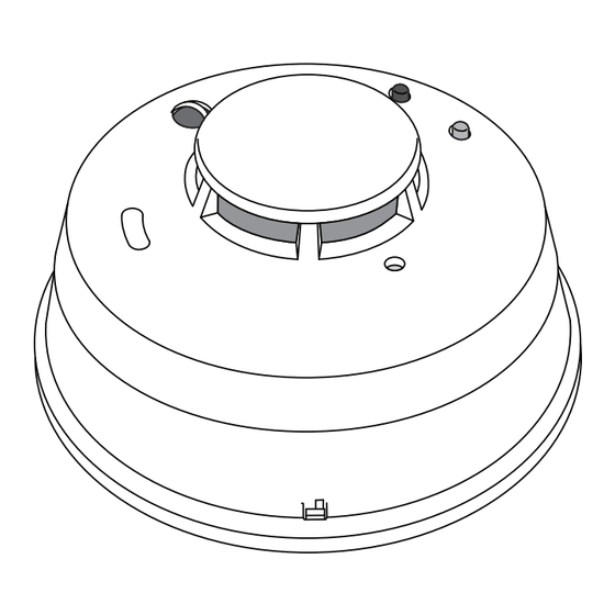
1164 FEATURES Cover Latch Cover Red LED Green LED Base Test Button Figure 1: 1164 Features 1164/1164NS Series Installation and Programming Guide... -
Page 7: Program The 1164
PROGRAM THE 1164 When programming an 1164/1164NS smoke detector, refer to the appropriate panel programming guide, as needed. PROGRAMMER MENU PROGRAMMER Enter 6653 (PROG) at the keypad to enter the PROGRAMMER menu. ZONE INFORMATION Press CMD until ZONE INFORMATION displays. Press a select ZONE INFORMATION key or area to enter the menu. -
Page 8: Next Zone
Enter the eight-digit SERIAL NO found on the device and press SERIAL NO: CMD. SUPERVISION TIME Enter 3 as the SUPVSN TIME, and then press CMD. SUPVSN TIME: 3 NEXT ZONE At the NEXT ZONE?, prompt, select NO. NEXT ZN? 1164/1164NS Series Installation and Programming Guide... -
Page 9: Bell Options
FIRE BELL ACTION FIRE BELL ACTION... At FIRE BELL ACTION FIRE TYPE:, select T (temporal) as the FIRE TYPE: action type. Note: Program this option to enable cadence synchronization with other 1164s on the system. 1164/1164NS Installation and Programming Guide... -
Page 10: Select A Location
LED blinks immediately on and immediately off. Faulty: If communication is faulty, the LED remains on for up to eight seconds or flashes multiple times in a quick succession. Relocate the wireless receiver until the LED confirms clear communication. 1164/1164NS Series Installation and Programming Guide... -
Page 11: Install The 1164
Grasp the detector and twist counterclockwise to remove the detector from the mounting base. See Figure 2. Use the supplied screws and anchors to mount the base to the surface. Figure 2: Remove Figure 3: Mounting Detector from Base Hole Locations 1164/1164NS Installation and Programming Guide... -
Page 12: Enable The Tamper Switch (Optional)
ENABLE THE TAMPER SWITCH (OPTIONAL) The 1164 features a tamper switch to send a trouble message to the panel if the detector is removed from the mounting base. To enable the tamper switch, follow the directions below: Identify the small plastic tab that’s located on the mounting base. -
Page 13: Install The Battery
Place the included battery into the battery compartment in the detector. The green Figure 5: Battery Location and red LEDs located on the 1164 cover will simultaneously flash four times, and then the green LED will flash every ten seconds indicating the detector is in standby. - Page 14 Red LED blinks Low Battery every 45 seconds Red LED Red LED blinks Maintenance 0.18 inch tool to every 5 seconds Needed press the test button Figure 6: Test Button Location Table 1: LED Operation 1164/1164NS Series Installation and Programming Guide...
-
Page 15: Test The 1164
Silence Alarm: (1164 only) When pressed during an alarm the sounder is disabled for five minutes. Silence Trouble Chirp: (1164 only) Press to silence a trouble chirp for 12 hours. If the test button is pressed during the silence period, the detector will not respond. If an alarm condition occurs during the silence period, the sounder will enable as per alarm requirements. -
Page 16: Clean The 1164
Replace the detector cap by lining up the new cap with the detector. Insert the cap into the smoke detector and twist it gently to the left until it snaps into place. 10. Reinsert the battery, and then reattach the detector to the mounting base. 1164/1164NS Series Installation and Programming Guide... - Page 17 Figure 7: Remove Detector Cap Figure 8: Detector Cover and Sensing Chamber 1164/1164NS Installation and Programming Guide...
-
Page 18: Mounting Guidelines
Mount smoke detectors on a firm, permanent surface. • Place in environmentally-controlled areas with a temperature range between 40° and 100° F (4.4° and 37.8° C) and the humidity is between 0 and 90% non- condensing. 1164/1164NS Series Installation and Programming Guide... -
Page 19: Authority Having Jurisdiction
For insurance purposes, an AHJ may be an insurance inspection department, rating bureau, or other insurance company representative. Sometimes, a property owner or their designated agent assumes the role of the AHJ. At government installations, the commanding officer or department official may be the AHJ. 1164/1164NS Installation and Programming Guide... -
Page 20: Locations To Avoid
• In dead-air spaces at the top of peaked ceilings or corners where walls and ceiling meet. • Near fluorescent light fixtures (smoke detectors should be at least 10 feet away). 1164/1164NS Series Installation and Programming Guide... -
Page 21: Commercial
Apartment Apartment Apartment Inside each apartment, First Floor place smoke detectors in the living area, hallway, and each bedroom. Living Room Figure 9: Smoke Detector Placement Locations Bathroom Bedroom 1164/1164NS Installation and Programming Guide... -
Page 22: Additional Information
If the receiver has been powered down for more than one hour, then the 1164/1164NS may take up to an additional hour to send a supervision message. A missing message may display on the keypad until the supervision message is sent. -
Page 23: Nfpa 72 Guidelines
(For exceptions, refer to NFPA 72 Spacing Requirements.) Where non required detection devices are installed for a specific hazard, additional non required detection devices shall not be required to be installed throughout an entire room or building. 1164/1164NS Installation and Programming Guide... - Page 24 Approved, single-station smoke alarms shall be installed in accordance with 7-6.2.10 of NFPA 101 outside every sleeping area in the immediate vicinity of the bedrooms and on all levels of the dwelling unit including basements. (For exceptions, refer to this section of NFPA 72.) 1164/1164NS Series Installation and Programming Guide...
- Page 25 1164/1164NS Installation and Programming Guide...
- Page 26 Use combustible materials and electrical appliances carefully and only for their intended uses. • Do not overload electrical outlets. • Do not store explosive and/or fast burning materials in your home. • Even after proper precautions have been taken, fires can start. Be prepared. 1164/1164NS Series Installation and Programming Guide...
-
Page 27: Compliance Specifications
85 dBa at 10 feet Temporal Sensitivity 2.0% Frequency Range 905-924 MHz Detector Dimensions 5.6”x 2.4” (14.3 cm x .046 cm) Base Dimensions 5.4” x 0.46” (13.7 cm x .46 cm) Color White PATENTS U.S. Patent No. 7,239,236 1164/1164NS Installation and Programming Guide... -
Page 28: Certifications
XT30/XT50 Series Panel (Version 123 or higher) XR150/XR550 Series Panel (Version 108 or higher) CERTIFICATIONS FCC Part 15 Registration ID CCKPC0104 IC Registration ID 5251A-PC0104 New York City (FDNY COA #6167) ANSI/UL 268 Smoke-Automatic Fire Detectors 1164/1164NS Series Installation and Programming Guide... -
Page 29: Fcc Information
Increase the separation between the equipment and receiver. • Connect the equipment into an outlet on a circuit different from that to which the receiver is connected. • Consult the dealer or an experienced radio/TV technician for help. 1164/1164NS Installation and Programming Guide... -
Page 30: Industry Canada Information
Information furnished is believed to be accurate and reliable. This information is subject to change without notice. 1164/1164NS Series Installation and Programming Guide... - Page 32 LT-1195 18245 1.02 © 2018 Digital Monitoring Products, Inc.
Need help?
Do you have a question about the 1164 and is the answer not in the manual?
Questions and answers