
Related Manuals for UNI electronic UM 4000

Summary of Contents for UNI electronic UM 4000
- Page 1 UM 4000 1HE Matrix Rackmixer 1RU Matrix Preamplifier Bedienungsanleitung User Manual BDA V200301DEEN...
- Page 2 Installations- und Aufstellungshinweise Um einen zuverlässigen Betrieb des Gerätes zu gewährleisten, sollten Sie diese Installations- und Aufstellungshinweise unbedingt berücksichtigen. Zur Vermeidung von Überhitzung, ist darauf zu achten, dass das Gehäuse, und/oder der Gestellschrank ausreichend belüftet ist und sich keine weiteren Wärmequellen in unmittelbarer Nähe befinden. Die zulässige Umgebungstemperatur von + 30°...
-
Page 3: Bedienelemente Und Anschlüsse
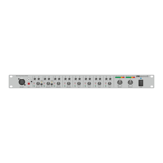
1. Bedienelemente und Anschlüsse 1.1 Frontansicht Mikrofon / Line Eingang Tieftonsteller Aux Eingang Peak Anzeige Tieftonsteller Signal Anzeige Pegeleinstellung Hochtonsteller Peak Anzeige Pegeleinstellung Signal Anzeige Aussteuerungsanzeige Hochtonsteller Master Pegeleinstellung VOX Anzeige Netzschalter VOX Pegeleinsteller 1.2 Rückansicht 230V Spannungsversorgung Slot für UMP 6M Gongmodul Audioausgänge AUX Eingänge Audiobus Eingang... -
Page 4: Ein / Ausgänge
1. Ein / Ausgänge 1.1 Anschluss der MIC/LINE Eingänge Alle vier LINE / MIC Eingänge besitzen auf der Rückseite eine XLR Buchse zur Einspeisung eines symmetrischen Audiosignals. Die Umschaltung zwischen Line und Mic erfolgt durch den „PAD“-Schalter (12.2) Ist dieser gedrückt, wird das Audiosignal um zusätzliche 30dB abgesenkt. Die Empfindlichkeit des Eingangsverstärkers können Sie mit den „GAIN“-Regler (12.3) im Bereich von –60dB bis +10dB anpassen. - Page 5 2. Audiobus / MUTE Link 2.1 Kaskadierung mehrerer Geräte Über die Audiobus IN und OUT Anschlüsse (10) ist es möglich 16 Geräte zu einer Einheit zu kombinieren. Im Maximalausbau stehen Ihnen somit 64 MIC/LINE und 48 AUX Eingänge zur Verfügung. Verbinden Sie die Geräte wie in oben dargestellt.
- Page 6 3. Konfiguration 3.1 Position der Jumper und Nachrüstmodule Austauschbarer Front XLR Anschluss für z.B. Gongstarttaster Jumper für Mono/Stereo Umschaltung der AUX Eingänge Jumper für Lowcut On/Off der Mic Eingänge Jumper für Eingangsrouting Jumper für MUTE-LINK Konfiguration und Routing Anschluss UMP 6M Einbauplatz für UPM 6M...
- Page 7 Position C 3.3 Low Cut Filter MIC 1 MIC 2 MIC 3 MIC 4 Für die Eingänge MIC 1 bis MIC 4 kann durch Umstecken eines Jumpers je Kanal ein 80Hz Lowcut aktiviert werden. Lowcut Im Auslieferzustand sind diese Jumper Ein/Aus alle auf „off“...
- Page 8 3.4 Blockübersicht Routing...
- Page 9 3.5 MIC 1 Blockdiagramm 3.6 MIC 2 Blockdiagramm 3.7 MIC 3 Blockdiagramm 3.8 MIC 4 Blockdiagramm...
- Page 10 3.9 AUX 1 Blockdiagramm 3.10 AUX 2 Blockdiagramm 3.11 AUX 3 Blockdiagramm 3.12 AUX 4 Blockdiagramm...
- Page 11 3.13 EMER Blockdiagramm 3.14 INSERT Blockdiagramm...
- Page 12 4. Nachrüstoptionen 4.1 UMP 6M - Alarm-, Gong-, Message-Player Modul Mit dem UMP 6M Modul bietet sich Ihnen die Möglichkeit, den UM 4000 mit einem hochwertigen Alarm-, Gong-, Message-Player nachzurüsten. Das Modul zeichnet sich durch einen 18 Bit D/A Wandler aus.
-
Page 13: Installation And Setup Instructions
Installation and setup instructions To ensure reliable and save operation of the unit, you should carefully read this instruction- and setup-manual. To prevent overheating, make sure that the cabinet and / or the rack is sufficiently ventilated and that there are no other heat sources in the immediate vicinity. -
Page 14: Controls And Connectors
1. Controls & Connectors 1.1 Front View Mikrophone / Line Input Bass Control Aux Input Peak Indicator Bass Control Signal Indicator Level Control Treble Control Peak Indicator Level Control Signal Indicator Level Indicator Treble Control Master Control VOX Indicator Power Switch VOX Level Control 1.2 Rear View 230V Power Connector... -
Page 15: Aux Inputs
1. In- / Outputs 1.1 MIC/LINE Inputs All four Mic/Line Inputs have an XLR connector at the rear panel to feed in an symmetric audio signal. Selection between mic and line is done with the “PAD” switch (12.2). If it is pressed the audio signal is being lowered by 30db. -
Page 16: Cascading Multiple Units
2. Audio Bus / MUTE Link 2.1 Cascading Multiple Units Via the AUDIO BUS IN and OUT connectors (10.1 & 10.2) 16 units UM 4000 can be combined to one system so that you have available max. 64 MIC/LINE and 48 AUX inputs. - Page 17 3. Configuration 3.1 Positions of Jumpers and Retrofittable Modules Replaceable front XLR connector f. integration of i.e. chime button or USB connector for DSP programming. Jumper for mono/stereo selection of AUX inputs Jumper for Lowcut On/Off of Mic inputs Jumper for input routing Jumper for MUTE-LINK mode and routing Connectors for UDSP 4046...
- Page 18 Position C 3.2 Low Cut MIC 1 MIC 2 MIC 3 MIC 4 For the inputs MIC 1 – Mic 4 a 80Hz low cut filter can be activated for each Lowcut channel by setting of a jumper. On/Off Factory setting is filter “off”. Position B 3.3 Mono / Stereo AUX 1...
- Page 19 3.4 Block Overview Routing...
- Page 20 3.5 MIC 1 Block Diagram 3.6 MIC 2 Block Diagram 3.7 MIC 3 Block Diagram 3.8 MIC 4 Block Diagram...
- Page 21 3.9 AUX 1 Block Diagram 3.10 AUX 2 Block Diagram 3.11 AUX 3 Block Diagram 3.12 AUX 4 Block Diagram...
- Page 22 3.13 EMER Block Diagramm 3.14 INSERT Block Diagram...
-
Page 23: Technische Daten / Specifications
SD card. The files can be triggered separately via the four trigger inputs available at the RJ 45 connector at the front of the unit. Three additional trigger inputs are available inside the UM 4000. Optionally the RJ 45 connector can be replaced by a trigger switch. This allows to start i.e. - Page 24 UNIelectronic Vertriebs GmbH Steinbrinksweg 25 D-31840 Hessisch Oldendorf Fon +49 5152 525220 info@unielectronic.com www.unielectronic.com...
Need help?
Do you have a question about the UM 4000 and is the answer not in the manual?
Questions and answers