Table of Contents
Advertisement
Advertisement
Table of Contents

Related Manuals for Calix E5-400


Summary of Contents for Calix E5-400
- Page 1 Calix E5-400 Installation Guide March 2009 #220-00211, Rev 13...
-
Page 3: Table Of Contents
Installing the E5-400 Fan Tray ..................26 Installing the Fan Tray Filter ................26 Installing the Fan Tray Module ................27 Proprietary Information: Not for use or disclosure except by written agreement with Calix. © 2001-2009 Calix. All Rights Reserved. - Page 4 Replacing the Fan Tray Module ................... 41 Appendix A: Reference Information ......... 43 E5-400 Specifications ....................44 Fiber Handling Techniques ..................45 Proprietary Information: Not for use or disclosure except by written agreement with Calix. © 2001-2009 Calix. All Rights Reserved.
-
Page 5: About This Guide
About This Guide This document provides a general installation practice for the Calix E5-400 Ethernet transport & aggregation platform. This document includes guidance for planning, power installation, cabling, and maintenance. Intended Audience This document is intended for use by network planning engineers, outside plant engineers, CO technicians, and field support personnel, as well as craft personnel responsible for equipment installation, cabling, and maintenance. - Page 6 MAY BE PRESENT. Fiber optic radiation can cause severe eye damage or blindness. Do not look into the open end of an optical fiber. Proprietary Information: Not for use or disclosure except by written agreement with Calix. © 2001-2009 Calix. All Rights Reserved.
-
Page 7: Chapter 1: Calix E5-400 Product Overview
Chapter 1 Calix E5-400 Product Overview This chapter introduces the Calix E5-400 Ethernet transport & aggregation platform and provides a general overview of the E5-400 small form factor chassis and components. Topics Covered This chapter covers the following topics: Introducing the Calix E5-400 ... -
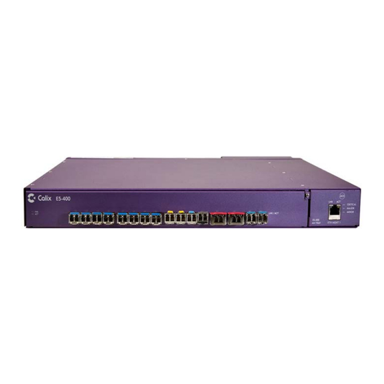
Page 8: Introducing The Calix E5-400
Fan tray assembly The E5-400 unit is equipped with a fan tray assembly that slides into the front of the chassis. The fan tray consists of the following controls and indicators: 10/100 Fast Ethernet management port with LNK and ACT LEDs ... - Page 9 Chassis Ground Lugs A/B Power Input -48V RTN A -48V A Alarm Interface Panel -48V RTN B -48V B Chassis Ground Lugs 5493 Proprietary Information: Not for use or disclosure except by written agreement with Calix. © 2001-2009 Calix. All Rights Reserved.
-
Page 10: Calix E5-400 Dimensions
Width: 2.625-inches (6.7 cm) Depth: 10.5-inches (26.7 cm) 2.875-inches 5464 CRITICAL 1.625-inches MAJOR MINOR E5-400 ETH MGMT 1 FAN TRAY 2.625-inches Proprietary Information: Not for use or disclosure except by written agreement with Calix. © 2001-2009 Calix. All Rights Reserved. -
Page 11: Chapter 2: Installation Considerations
This section covers the following topics: Installation process overview Installation guidelines General safety recommendations E5-400 materials and tools checklist Facility requirements Proprietary Information: Not for use or disclosure except by written agreement with Calix. © 2001-2009 Calix. All Rights Reserved. -
Page 12: Installation Guidelines
For safety, keep bystanders and other unauthorized personnel away from work operations at all times. If the E5-400 is to be installed in an outdoor cabinet, do not perform installation activities during thunderstorms or when the threat of lightning is present. -
Page 13: General Safety Recommendations
ESD ALERT! Beware of electrostatic discharge. Follow standard ESD precautions. Always wear a grounded ESD wristband to avoid damaging the electronic equipment. Proprietary Information: Not for use or disclosure except by written agreement with Calix. © 2001-2009 Calix. All Rights Reserved. -
Page 14: Installation Process Overview
Grounding the E5-400 chassis Installing the fan tray Connecting power Wiring alarms Installing transceiver modules Terminating fibers Proprietary Information: Not for use or disclosure except by written agreement with Calix. © 2001-2009 Calix. All Rights Reserved. -
Page 15: Materials And Tools Checklist
Up to (2) XFP optics modules (ordered and packaged separately) Up to (2) SFP+ optics modules (ordered and packaged separately) User-supplied materials The following materials are required to complete an E5-400 installation, but are not supplied by Calix: 19- or 23-inch equipment rack ... - Page 16 Depending on the system configuration, the following test equipment may be needed: Digital Volt/Ohm meter Optical power meter Bit Error Rate tester Proprietary Information: Not for use or disclosure except by written agreement with Calix. © 2001-2009 Calix. All Rights Reserved.
-
Page 17: Facility Requirements
Assignments for power, services, transport, alarms, timing, and other interfaces have been defined. Note: For circuit breaker panel installation instructions, refer to the appropriate vendor documentation. Proprietary Information: Not for use or disclosure except by written agreement with Calix. © 2001-2009 Calix. All Rights Reserved. - Page 18 Proprietary Information: Not for use or disclosure except by written agreement with Calix. © 2001-2009 Calix. All Rights Reserved.
-
Page 19: Chapter 3: Installing The Calix E5-400
Chapter 3 Installing the Calix E5-400 This section describes how to install the Calix E5-400 small form-factor chassis onto a standard equipment rack, including how to install power and grounding. Topics Covered This section covers the following topics: Installing the E5-400 chassis ... -
Page 20: Installing The E5-400 Chassis
For rack mounted systems, keep the following in mind: The E5-400 fan tray is located on the right side of the unit. Adequate airflow on the right and left (exhaust) sides of the E5-400 is required to properly cool the unit. -
Page 21: Installing The Mounting Ears
2. Get the appropriate pair of mounting ears and (8) flat head screws from the kit. 3. Secure the mounting ears to the side of the E5-400 unit (four screws per side) as shown. Note: This unit is equipped with three positions for placement of mounting ears, to support front and mid-mount rack installation depths. -
Page 22: Mounting The Unit In An Equipment Rack
Position the E5-400 chassis against the equipment rack at the mounting location to determine the mounting holes to use. b. While holding the E5-400 in position against the rack, insert (1) mounting screw into the top hole on each ear. -
Page 23: Grounding The Chassis
ESD ALERT! Beware of electrostatic discharge. Follow standard ESD precautions. Always wear a grounded ESD wristband to avoid damaging the electronic equipment. The E5-400 employs a common ground and must be grounded to a Common Bonding Network. To ground the E5-400 chassis... -
Page 24: Connecting Dc Power
Note: Make sure the -48 VDC power source is within 12-feet of the E5-400 unit (allowing for bends and cable management as required). 2. Connect the lugged end of the power wires to the terminals on the back of the E5-400 as shown. -
Page 25: Testing The Power Supply Levels
To test power to the E5-400 1. Verify that the –48 VDC power supply is "on" at the source. 2. Using a digital volt meter, test the input power at the E5-400 power terminals located on the rear panel: a. Place the volt meter positive lead on the A-side negative (-48V A) terminal lug. -
Page 26: Installing The E5-400 Fan Tray
Note: The fan tray filter is designed for use in indoor or office environments. For remote cabinet mounting, the fan tray filter must be removed. Note: Install the fan tray filter before installing the fan tray into the E5-400. To install the fan tray filter 1. -
Page 27: Installing The Fan Tray Module
1. Remove the fan tray module from its packaging. 2. Slide the fan tray module into the housing on the right side of the E5-400 front panel. Note: As the module interfaces with the E5-400 backplane, an increase in resistance occurs. - Page 28 Proprietary Information: Not for use or disclosure except by written agreement with Calix. © 2001-2009 Calix. All Rights Reserved.
-
Page 29: Chapter 4: Wiring The E5-400 Network Interfaces
Chapter 4 Wiring the E5-400 Network Interfaces This section describes how to wire external interfaces to the Calix E5-400 chassis, including alarms, management, and Ethernet line interfaces. Topics Covered This section covers the following topics: Wiring the E5-400 out-of-band management interfaces ... -
Page 30: Wiring The Out-Of-Band Management Interfaces
Note: The E5-400 front Ethernet management port auto-senses transmit and receive signals. Use either a straight-through or cross-over cable to connect to the Ethernet port. 2. Connect one cable end to the E5-400 Ethernet management port, located on the front panel (labeled ETH MGMT 1). -
Page 31: Connecting To The Rear Ethernet Management Port
2. Separate out the orange and green wire pairs, and then strip off one inch of insulation from each wire. 3. Connect the orange and green pairs to the wire-wrap pins on the E5-400 rear panel as follows: Attach the white/orange wire to the ETX+ pin. -
Page 32: Connecting To The Rs-232 Serial Port
2. Separate out the wires associated with pins 2, 3, and 5 of the DB-9 connector. Strip off one inch of insulation from each wire. 3. Connect the identified wires to the wire-wrap pins on the E5-400 rear panel as follows: Attach the wire associated with pin #2 to the CUTX pin. -
Page 33: Wiring The Alarm Interfaces
See the Calix E5-400 User Guide for descriptions of the available alarms. Wiring Environmental Alarms The E5-400 alarm interface is located on the rear of the E5-400 unit immediately to the right of the ground bus bar. Definitions of each alarm pin pair are included below:... -
Page 34: Wiring Audible And Visual Alarms
3. Strip insulation from the ends of the three wire pairs to connect to the unit. 4. On the E5-400 rear panel, connect the alarm wires to the alarm pin fields as follows: a. Wrap the first pair of wires to the AL0+ and AL0- pins for reporting Critical alarm activity (Audible). -
Page 35: Wiring The Ethernet Line Interfaces
The hot-swappable GBIC transceivers are modular units that house a transmitter and a receiver. E5-400 units do not ship with GBIC transceivers. Use transceivers that comply with the SFP Transceiver MultiSource Agreement (MSA). See the Small Form Factor (SFF) committee INF-8074i specification Rev 1.0 for details. -
Page 36: Installing And Removing A Transceiver Module
1. Remove the dust cover from the transceiver. 2. For transceivers with a flip-up or flip-down latch, close the latch. 3. Insert the transceiver into the E5-400 slot with the exposed section of PCB board facing down. 4. Press the transceiver firmly until it clicks into place. -
Page 37: Terminating Fibers
Terminating Fibers Once SFP transceiver modules are installed in the E5-400 chassis, you can terminate fibers to the SFPs. Be sure the connector type on the fibers matches the connector type on the SFP module(s). If the laser at the far end of the fibers is enabled, you can use an optical power meter to test the signal strength on the fibers before connecting to the equipment. - Page 38 Proprietary Information: Not for use or disclosure except by written agreement with Calix. © 2001-2009 Calix. All Rights Reserved.
-
Page 39: Chapter 5: Maintenance
This chapter describes how to perform routine maintenance on worn or failed equipment. Topics Covered This chapter covers the following topics: Fan tray filter maintenance Replacing the fan tray module Proprietary Information: Not for use or disclosure except by written agreement with Calix. © 2001-2009 Calix. All Rights Reserved. -
Page 40: Fan Tray Filter Maintenance
1. Using a #1 Phillips screwdriver, loosen the captive fan tray screw. 2. Grasp the ejection lever and pull the fan tray assembly out of the E5-400 chassis. Note: The E5-400 fan tray assembly is hot pluggable and can be removed with power applied. -
Page 41: Replacing The Fan Tray Module
Replacing the Fan Tray Module The E5-400 has a hot-swappable fan module on the right side of the front panel. You can remove and install the fan module while the system remains powered. Note: You can remove and install the fan module while the system remains powered on without interrupting service or system operation. - Page 42 Note: If the replacement fan module does not operate, power down the system and contact the Calix Technical Assistance Center (TAC). Proprietary Information: Not for use or disclosure except by written agreement with Calix. © 2001-2009 Calix. All Rights Reserved.
-
Page 43: Appendix A: Reference Information
This appendix provides general information about the E5-400 transport and aggregation platform. Topics Covered This appendix covers the following topics: E5-400 specifications Fiber handling techniques Proprietary Information: Not for use or disclosure except by written agreement with Calix. © 2001-2009 Calix. All Rights Reserved. -
Page 44: E5-400 Specifications
Critical, Major, and Minor Audible and Alarm Cut-off (ACO) and Alarm LEDs Visual Alarms (Critical, Major, and Minor) Fan Tray 4 fans mounted in line. Proprietary Information: Not for use or disclosure except by written agreement with Calix. © 2001-2009 Calix. All Rights Reserved. -
Page 45: Fiber Handling Techniques
Coil the successful splice inside the splice tray, taking care not to exceed the bend radius parameters of the cable. Proprietary Information: Not for use or disclosure except by written agreement with Calix. © 2001-2009 Calix. All Rights Reserved. - Page 46 Never attempt to insert the connector by gripping the white or green flexible shroud. This may cause the fiber to kink in the jacket, introducing unwanted noise to the line. Proprietary Information: Not for use or disclosure except by written agreement with Calix. © 2001-2009 Calix. All Rights Reserved.
Need help?
Do you have a question about the E5-400 and is the answer not in the manual?
Questions and answers