Table of Contents
Advertisement
Available languages
Available languages
Quick Links
Advertisement
Table of Contents

Subscribe to Our Youtube Channel
Related Manuals for Velleman K4306


Summary of Contents for Velleman K4306
- Page 1 K4306 2 x 15 LED stereo VU-meter ........3 VU - mètre stéréo à 2 x 15 DEL ......7 2 x 15 LED stereo-VU-meter ........7 H4306B-1...
- Page 2 VELLEMAN NV Legen Heirweg 33 9890 Gavere Belgium Europe www.velleman.be www.velleman-kit.com...
-
Page 3: Technische Gegevens
2 x 15 LED STEREO VU METER SPECIFICATIES : Om audiosignalen te visualiseren. Kan worden gebruikt met mengpanelen, versterkers, audiosystemen voor in de auto etc. LOW INPUT: gemakkelijk aansluitbaar op de lijnuitgang van een cassettedeck, stereosysteem of cd-speler. ... -
Page 4: Alvorens Te Beginnen
ALVORENS TE BEGINNEN Zie ook de algemene handleiding voor soldeertips en andere algemene informatie (vb. Kleurencodering voor weerstanden en LEDs). Benodigdheden om de kit te bouwen: Kleine soldeerbout van max 40W. Dun 1mm soldeersel, zonder soldeervet. Een kleine kniptang. 1. - Page 5 Monteer de trimpotentiometers. Monteer de elektrolytische condensatoren. Let op de polariteit. 10. Monteer de 1W weerstanden. Zorg ervoor dat deze 2mm van de print gemonteerd word (zie figuur) 11. Monteer de LEDs op hun correcte hoogte. Let op de polariteit! 12.
- Page 6 16. AANSLUITING MET EEN AUTORADIO (Fig. 6.0) : Aansluiting op een luidsprekeruitgang van een gewone autoradio. OPMERKING: Sluit het toestel niet aan op een versterker of autoradio met hoog vermogen: deze toestellen maken gebruik van een geïsoleerde aarding. Door dit soort toestellen aan te sluiten kunt u de versterker of de autoradio blijvende beschadigen! ...
- Page 7 VU-METRE STEREO A 2 X 15 DEL SPECIFICATIONS : Pour visualiser des signaux audio. Peut être utilisé avec des panneaux de mixage, des amplificateurs, des systèmes audio pour voitures etc. LOW INPUT: pour connecter à la sortie ligne d'un lecteur de cassettes, de CD ou d'une chaîne stéréo. ...
-
Page 8: Avant De Commencer
AVANT DE COMMENCER Lisez également les astuces pour le soudage et d'autres infos générales dans la notice (p.ex. le code couleurs des résistances et des LEDs). Matériel nécessaire pour le montage du kit: Petit fer à souder de max. 40W. ... - Page 9 Montez les condensateurs en céramique. Montez les potentiomètres de réglage. Montez les condensateurs électrolytiques. Attention à la polarité. 10. Montez les résistances 1W. Veillez à ce que le boîtier de cette résistance se trouve à une distance d‘environ 2mm du circuit imprimé, voir figure.
- Page 10 16. CONNEXION AVEC UN AUTORADIO (Fig. 6.0) : Connexion à une sortie haut-parleur d'un autoradio normal. REMARQUE: Ne connectez pas l'appareil à un amplificateur ou un autoradio à haute puissance, car ces appareils utilisent une connexion à la masse isolée. Une connexion à un tel type d'amplificateur peut causer des dommages permanents à...
-
Page 11: Technische Eigenschaften
Systeme* verbunden werden kann. Um das K4306 universell einsetzbar zu machen, kann die Ablesung als DOT oder BAR-Anzeige eingestellt werden. Das mitgelieferte Displayfenster für vertikale oder horizontale Montage macht die Einheit zu einem sehr attraktiven Gerät. -
Page 12: Bevor Sie Anfangen
BEVOR SIE ANFANGEN Siehe auch die allgemeine Anleitung für Löthinweise und andere allgemeine Informationen (z.B. die Farbcodierung für Widerstände und LEDs). Zum Bau notwendiges Material: Kleiner Lötkolben von höchstens 40W. Dünnes Lötmetall von 1mm, ohne Lötfett. Eine kleine Kneifzange. 1. - Page 13 7. Montieren Sie die Keramikkondensatoren. 8. Montieren Sie die Trimmpotentiometer. 9. Montieren Sie die Elektrolytkondensatoren. Achten Sie auf die Polarität 10. Montieren Sie die 1W-Widerstände. Sorgen sie dafür, dass das gehäuse des Widerstand sich ungefähr 2mm von der Leiterplatte entfernt befindet. 11.
- Page 14 16. VERBINDUNG MIT EINEM LAUTSPRECHER-AUSGANG (Abb. 6.0) : Verbindung mit einem Lautsprecher-Ausgang eines Autoradios HINWEIS: Schließen Sie die Einheit nicht an einen High-Power Autoverstärker oder ein Autoradio an, diese Geräte verwenden eine isolierte Erdverbindung. Der Anschluss mit einem solchen Verstärker kann den Verstärker oder das Autoradio permanent beschädigen ! ...
- Page 16 VELLEMAN NV Legen Heirweg 33, B-9890 GAVERE Belgium (Europe) Modifications and typographical errors reserved © Velleman nv. H4306B - 2014 - ED1 (rev.1) 5 4 1 0 3 2 9 2 8 9 9 4 2...
- Page 17 Total solder points: 271 Difficulty level: beginner 1 2 3 4 5 advanced 2 x 15 LED STEREO VU METER K4306 ILLUSTRATED ASSEMBLY MANUAL H4306IP-1...
-
Page 18: Specifications
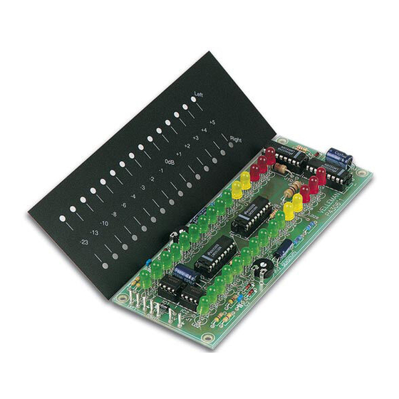
Features & Specifications Features: For visualization of audio signals. Use with mixing panels, amplifiers, car audio systems… Easily connects to the line-level output (LOW INPUT) from any tape deck, stereo system, or CD player. A special input (HIGH INPUT) is provided, so that the unit can directly be connected to the speaker ... - Page 19 Assembly hints 1. Assembly (Skipping this can lead to troubles ! ) Ok, so we have your attention. These hints will help you to make this project successful. Read them carefully. 1.1 Make sure you have the right tools: A good quality soldering iron (25-40W) with a small tip.
- Page 20 Assembly hints 1.3 Soldering Hints : 1- Mount the component against the PCB surface and carefully solder the leads 2- Make sure the solder joints are cone-shaped and shiny 3- Trim excess leads as close as possible to the solder joint REMOVE THEM FROM THE TAPE ONE AT A TIME ! DO NOT BLINDLY FOLLOW THE ORDER OF THE COMPONENTS ONTO THE TAPE.
-
Page 21: Jumper Wires
Construction 1. Jumper wires BAR readout : JB1 JB2 JB3 JB4 J1 J7 DOT readout : J2 J8 J3 J9 J4 J10 J5 J11 JD1 ... - Page 22 Construction 2. Diodes. Watch the polarity ! 4. Metal film resistors R10 : 47K (4 - 7 - 3 - B) R11 : 2K2 (2 - 2 - 2 - B) R12 : 18K (1 - 8 - 3 - B) R...
-
Page 23: Trim Potentiometers
Construction 7. Capacitors. 9. Electrolytic Capacitors. 11. LEDs. Watch the polarity! Watch the polarity ! C... C... 23mm 13mm LD... 0.9" CATHODE C1 : 220nF (224) C4 : 470µF C2 : 220nF (224) C5 : 47µF ... - Page 24 Construction LD13 : green 12. IC’s. Watch the polarity ! LD14 : green LD15 : green LD16 : green LD17 : green LD18 : green LD19 : green LD20 : green LD21 : yellow ...
- Page 25 Assembly 13. Assembly 141.5 21.5 Ø3.5 (A) Make the holes in the housing or panel (fig.1.0) : 6mm M3 COUNTERSUNK-HEAD BOLT Fig. 1.0 (B) Mount the suitable spacers (fig. 2.0) : 10mm M3 SPACER LOCK WASHER 6mm M3 COUNTERSUNK-HEAD BOLT 2...3mm FRONTPANEL SHAKEPROOF WASHER 10mm M3 SPACER...
- Page 26 Assembly (C) Mount the PCB onto the spacers (fig 3.0) : 6mm M3 COUNTERSUNK-HEAD BOLT 2...3mm FRONTPANEL 4mm M3 BOLT SHAKEPROOF WASHER 10mm M3 SPACER 4mm M3 BOLT Fig. 3.0...
- Page 27 14. Connection to a suitable signal Connecting to a line level output (tuner, preamplifier, cd player… ) and connecting a power supply from 12 to 15VDC / 300mA max.. LEFT TAPE HI RIGHT FROM AUDIO AMPLIFIER K4306 1N4007 1000uF/25V 12V/300mA MAINS 12V/300mA 12...15VDC...
- Page 28 15. Connection to a speaker output Connecting to a speaker level output and connecting a power supply from 12 to 15VDC / 300mA max. LEFT SPEAKER LEFT INPUT (0) RIGHT SPEAKER RIGHT FROM POWER AMPLIFIER K4306 1N4007 1000uF/25V 12V/300mA MAINS 12V/300mA 12...15VDC 1N4007...
- Page 29 LEFT SPEAKER LEFT RIGHT SPEAKER RIGHT +12V ANTENNE POWER OUT K4306 CAR RADIO Fig. 6.0 REMARK: Do not connect the unit to a high power car booster or car stereo, this equipment uses isolated ground connection. The connection to this kind of amplifier can cause permanent damage to the amplifier or car radio! ...
-
Page 30: Pcb Layout
17. PCB LAYOUT... - Page 31 Diagram 18. DIAGRAM HIGH IN 470K LOW IN 220K +5dB LD29 +5dB LD30 220n RIGHT LD27 LD28 +4dB +4dB 1N4148 MODE MODE DOT/BAR DOT/BAR LD25 LD26 +3dB +3dB LM3916 LM3916 +2dB LD23 +2dB LD24 1N4148 YELLOW YELLOW +1dB LD21 +1dB LD22 UA741 YELLOW...
- Page 32 VELLEMAN NV Legen Heirweg 33, B-9890 GAVERE Belgium (Europe) Modifications and typographical errors reserved © Velleman nv. H4306IP - 2014 - ED1 (rev.1) 5 4 1 0 3 2 9 2 8 9 9 5 9...
Need help?
Do you have a question about the K4306 and is the answer not in the manual?
Questions and answers